Eduard
1/48 Fw 190A-8/R2
| KIT #: | 8175 |
| PRICE: | $40.00 SRP |
| DECALS: | Six options |
| REVIEWER: | Lee Fogel |
| NOTES: | Patience, patience and more patience will yield a terrific replica! |
| HISTORY |
The Focke-Wulf
Fw 190 A-8 entered production in
February 1944 and was either powered by the standard BMW 801 D-2 or the 801Q
(also known as 801TU). From the A-8 on Fw 190s could be fitted with a new
paddle-bladed wooden propeller, easily identified by its wide blades with curved
tips. Externally, a large round hatch was incorporated into the lower fuselage
to enable 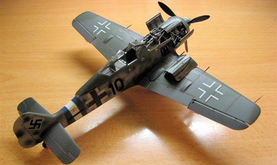 the new tank to be installed and the pilot's oxygen bottles were moved
aft and positioned around this hatch. A fuel filler panel was added to the port
side, below the rear canopy and a rectangular radio access hatch was added to
starboard. Other changes included an
the new tank to be installed and the pilot's oxygen bottles were moved
aft and positioned around this hatch. A fuel filler panel was added to the port
side, below the rear canopy and a rectangular radio access hatch was added to
starboard. Other changes included an
he Morane "whip" aerial for Y-Verfahren was fitted as standard under the port wing, just aft of the wheel-well. Nearly a dozen Rüstsätze kits were made available for the A-8, including the famous A-8/R2 and A-8/R8 Sturmbock models. The A-8/R2 replaced the outer wing 20 mm cannon with a 30 mm (1.18 in) MK 108 cannon, and some were fitted with heavy armor including 30 mm (1.18 in) canopy and windscreen armor and 5 mm ( in) cockpit armor. The A-8 was the most numerous of the Fw 190 A's, with over 6,550 A-8 airframes produced from March 1944 to May 1945. A-8's were produced by at least eight factories during its lifetime.
| THE KIT |
 Ever since the Eduard release of the Fw 190
came out I had wanted to see what all the fuss was.
Being a big fan of the Trimaster Fw 190A series I admit ahead of time
that I was going to be hard to please.
And the Tamiya kits of the A series are nothing to sneeze at either.
So, is the Eduard kit going to make me unload my beloved Trimaster/DML
kits?
Ever since the Eduard release of the Fw 190
came out I had wanted to see what all the fuss was.
Being a big fan of the Trimaster Fw 190A series I admit ahead of time
that I was going to be hard to please.
And the Tamiya kits of the A series are nothing to sneeze at either.
So, is the Eduard kit going to make me unload my beloved Trimaster/DML
kits?
Upon opening the box you are really overwhelmed
by the sheer amount of plastic inside.
There are quite a few spare parts that will be unused.
However not all of the spares are labeled as such in the instructions.
The clear sprue has both an “open” and “closed” version of the canopy as
well as the R2 armored glass for the canopy and a clear upper cowling panel.
Also included is a moderate sized PE fret of pre-colored cockpit and
detail parts. Speaking of the
instructions they are a color pamphlet with a brief but detailed history of the
A-8 model and the R2 version.
Exploded views as well as detailed step by step instructions help explain the
building procedure. The decal
placement pages have color three-view artists renderings of each decal option
along with a detailed description and history of each plane.
A very detailed color history booklet of the
| CONSTRUCTION |
I starting things off by jumped ahead and began
by assembling the wings/gear bay assembly first.
I had read numerous reviews and builds stating that this is the one area
that requires paying very close attention to the steps and placement of parts.
So, I thought, let’s get the hard part out of the way first.
Tedious might be a better word for it actually.
Due to the way the gear bay assembles if you do not get the proper angle
of the bay inserts the rest of the bay will be off kilter and will not line up
very well. I figured I had done a
decent job of lining it all up but once I put the middle section in I realized
that A) my lower wing had a slight warp and B) I was indeed off.
So, I repositioned the parts again the best I could. I even used the tops
of the wings to get the proper angle but to no avail.
The gaps on the leading edge were pretty
big. Plus there was a slight step
as well. So, more trimming of the
inner braces and making sure my positioning was correct.
This time most of the gaps disappeared but the steps were barely
affected. After yet a third time to
trim the inner braces I finally got the upper port wing to have only a small
step. No luck for the starboard
though. At this point I painted the
gear bay Model Master RLM 02 and set this section aside.
While this was drying I cut out the area of the wings where the inboard
gun bays are to be displayed opened up.
You can get a flush fit if you take more time (and
patience) than I did. Trim
small amounts and test fit. I did
it twice for each wing and that was good enough for me.
Once this was done I glued the upper wings to the lower wing section
using Plastruct liquid cement.
The next step I backtracked a bit and proceeded
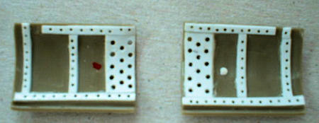
to build the cockpit. Eduard calls
for you to sand off the raised detail on parts H16 and H22 to glue the PE
consoles on. However I used the
pieces as templates and made a pair of flat consoles with sheet
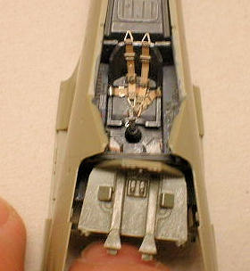 styrene.
More spares and less work for the same results…I like it!
The PE is very delicate but will take a few attempts to get the correct
bends. But on the sharp 90 degree
bends the tampos tended to flake apart at the bend.
So, bend once and use a dab of super glue if your tampo pops up.
This worked best for me and in no time the cockpit came together.
I used Model Master RLM 66 for this area.
The RLM 66 that Eduard uses for the tampos has a bit more of a blue hue
to it upon close inspection. Once
you have the cockpit and fuselage buttoned up though you really cannot tell the
difference. I added a bit of color
to a few panels and switches upon further research and this improved the look of
things a bit. At this point I glued
together the firewall/gun bay and painted it RLM 02.
styrene.
More spares and less work for the same results…I like it!
The PE is very delicate but will take a few attempts to get the correct
bends. But on the sharp 90 degree
bends the tampos tended to flake apart at the bend.
So, bend once and use a dab of super glue if your tampo pops up.
This worked best for me and in no time the cockpit came together.
I used Model Master RLM 66 for this area.
The RLM 66 that Eduard uses for the tampos has a bit more of a blue hue
to it upon close inspection. Once
you have the cockpit and fuselage buttoned up though you really cannot tell the
difference. I added a bit of color
to a few panels and switches upon further research and this improved the look of
things a bit. At this point I glued
together the firewall/gun bay and painted it RLM 02.
Moving right along the following day I glued the fuselage halves together. Checking the fit to the wings initially did not look too bad but the front bottom of the fuselage halves was bumping against the wheel well area especially on the port side. So, I did a bit of trimming and filing to get that area to fir better. At this time I glued the cockpit into place and allowed it to dry. It was now that disaster struck! The width of the front of the cockpit floor had spread the fuselage halves to the point that it would not fit between the wing roots! So, I cut out the front mounting tabs off of the cockpit floor part I17 and tried it a second time with (limited) success. The fuselage fit now in the wing roots but there was a noticeable gap on the port side. So, I used a small sliver of sheet styrene to fill the lower section of the gap and then used a few coats of Plastruct cement to fill in the smaller gap in the middle of the wing root.
There was an even bigger problem now.
The firewall/gun bay had a very large gap and would not even touch the
sides of the fuselage. Argh!
After much fussing and scratching of my head I used a modeler’s best
“persuader”…super glue. And lots of
it! I started with the lower area
where the engine mounts to and worked my way up to the cockpit coaming.
This took about 10-15 minutes just to make sure that the bond would not
separate as I did not use any accelerant.
I’m still not 100% thrilled with how this all “fits” together but the
entire area looks passable to me.
One word of note here though.
Eduard includes four parts that comprise the cowling guns.
However no mention is made in the instructions about placement of them!
The four parts are H18 thru 21.
This particular release is designed to be “buttoned up” but this area is
easily opened and the instructions to include the four-part assembly really
ought to be included. This can be
found on Eduard’s website. Look
under “cancelled products” and you will find the Royal Class boxing of the
A-8/R2. From that you can click and
download the page that shows the installation of the cowling guns.
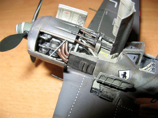
 The next step was the assembly of the BMW 801
engine. Although not entirely
complete it gives a good representation of this motor for someone to super
detail. For me it seemed like such
a waste to hide the motor under the cowling.
So, taking my cue from a nice build in the Osprey manual “Modeling the Fw
190” I decided to separate the upper cowling flaps from the lower bulged covers.
Quick use of a small saw did this and I used a dot of red paint and white
paint to keep the correct pieces paired up.
I added the cowling bracing and heat shields with sheet styrene and then
used a Dremel with a .35 size bit to make the smaller holes and a .5 size bit
for the larger holes on the heat shields.
The next step was the assembly of the BMW 801
engine. Although not entirely
complete it gives a good representation of this motor for someone to super
detail. For me it seemed like such
a waste to hide the motor under the cowling.
So, taking my cue from a nice build in the Osprey manual “Modeling the Fw
190” I decided to separate the upper cowling flaps from the lower bulged covers.
Quick use of a small saw did this and I used a dot of red paint and white
paint to keep the correct pieces paired up.
I added the cowling bracing and heat shields with sheet styrene and then
used a Dremel with a .35 size bit to make the smaller holes and a .5 size bit
for the larger holes on the heat shields.
Now that the cowling was appropriately modified I assembled the motor per
the instructions. Everything went
together very well. Eduard supplies
a jig for the eight exhaust pipes and it is a lifesaver!
I don’t think that I lined up the engine banks exactly right though and
it made it tougher to get the pipes glued into place with one of them being at a
shortened length compared to the rest.
But it is what it is. At
this point I decided to add a few different colored wires to the back of the
motor to add some detail. I used a
US Army spool of trip wire for this.
After drilling a few holes into the cowling/gun bulkhead I slipped the
wires into pre-drilled holes and attempted to fit the motor to the airframe.
“Attempted” is the key word.
I had to use the wires I added to hold the motor into place while I pressed the
assembly into place. The side
engine struts are a tad too long while the top is okay in length.
After six times of this I fit the engine at an acceptable angle and then
glued the struts into place using super glue and tweezers.
If this seems like a hassle, well, it is.
An option that
 did occur to me was to use the spare BMW 801 engine front
from the Tamiya Fw 190D-9 kit and modify it to fit with the cowling and upper
gun bay closed. Make sure to use
the fan from the Eduard kit if you attempt this.
I may try this on the next Eduard ‘190 I build just to see how viable an
option it is.
did occur to me was to use the spare BMW 801 engine front
from the Tamiya Fw 190D-9 kit and modify it to fit with the cowling and upper
gun bay closed. Make sure to use
the fan from the Eduard kit if you attempt this.
I may try this on the next Eduard ‘190 I build just to see how viable an
option it is.
Proceeding with the build I attached the main landing gear. The assembly went very quick and smooth but, again, my slight misalignment of the gear bay put the port gear leg at a wrong angle. I finessed the position the best I could and moved on to the remaining fiddly bits. These pieces all went on fine. The cowl cooling flaps require a slight bend to look “right”. I achieved this by using a smooth handled paint brush and rolling each flap against my finger. This ensured a soft bend. The foot step was broken and rather than repair it I used PE part PE37 that I had leftover from the PE fret. I bent it to the shape of the step and it worked very well.
You are given the choice of a plastic or PE antenna and I chose the PE
piece which looks much better. The
inside of the canopy was painted RLM 66 and the cowling parts and pieces were
now attached using
| COLORS & MARKINGS |
The canopy was masked off with Bare Metal Foil
and attached to the airframe. The
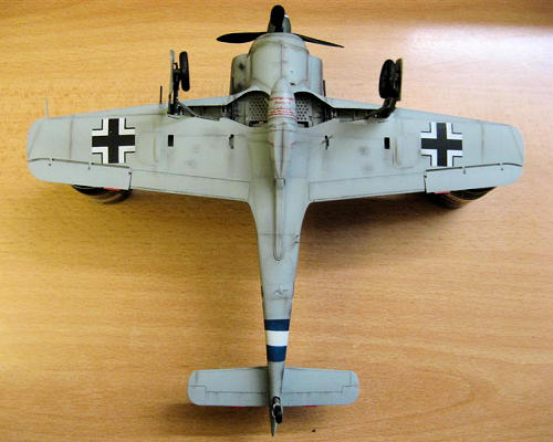
kit comes with six different decal options all based around the standard RLM
74/75/76 scheme. Four of the
options have Reich Defense bands and unit bands that are to be painted on as
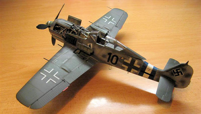
well. I chose option (3) “Schwarze
10” flown by Karl Spenst of 8./JG 300 with a striking blue/white/blue band.
I 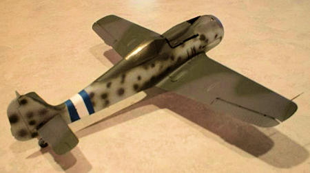 used Floquil enamels for the standard camouflage and a mixture of
Tamiya Flat Blue and MM Flat White for the blue/white/blue bands.
This required a bit of touch-up to the white.
Then the kit was glossed for decals.
The kit-supplied decals went on without a hitch.
Registration and opacity is very good and there are two complete sets of
stencils and wing walks in both black and grey.
The decals can also take a bit of abuse as I had to chase one around the
wing as it folded over itself. No
rips or tears and it snuggled right down with a dab of Solvaset!
The prop blades were painted with
Floquil RLM 70 and the hub detailed with black and silver paints.
The spinner was painted MM RLM 71 and the white spiral decal went down
very well. Use plenty of water to
get it positioned into place as the Eduard decals can be a bit “grabby” when
first laid down onto the surface. I
then added the drop tank and drilled two small holes in the mount and drop tank
to add fuel lines. I used brass
wire painted dark brown to replicate these lines and attached them to the mount
using super glue. The last
additions were the gun barrels and these were painted MM flat black and the
dry-brushed with Testors steel. The
canopy was attached in the open position with 5-minute epoxy.
used Floquil enamels for the standard camouflage and a mixture of
Tamiya Flat Blue and MM Flat White for the blue/white/blue bands.
This required a bit of touch-up to the white.
Then the kit was glossed for decals.
The kit-supplied decals went on without a hitch.
Registration and opacity is very good and there are two complete sets of
stencils and wing walks in both black and grey.
The decals can also take a bit of abuse as I had to chase one around the
wing as it folded over itself. No
rips or tears and it snuggled right down with a dab of Solvaset!
The prop blades were painted with
Floquil RLM 70 and the hub detailed with black and silver paints.
The spinner was painted MM RLM 71 and the white spiral decal went down
very well. Use plenty of water to
get it positioned into place as the Eduard decals can be a bit “grabby” when
first laid down onto the surface. I
then added the drop tank and drilled two small holes in the mount and drop tank
to add fuel lines. I used brass
wire painted dark brown to replicate these lines and attached them to the mount
using super glue. The last
additions were the gun barrels and these were painted MM flat black and the
dry-brushed with Testors steel. The
canopy was attached in the open position with 5-minute epoxy.
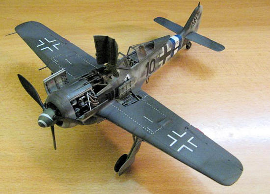
Weathering consisted of using Formula P3 Armor Wash for an oily wash on the drop tank, open port gun panel, main gear and the cowl panels. For panel lines, exhaust, gear bays, wheels and gun residue I used my trusty set of chalk pastels and a .07 Pentel mechanical pencil. The landing lights were painted using Tamiya clear red and green.
| CONCLUSIONS |
Holy cow, where do I begin?
By far and away this is the most detailed Fw 190A kit on the market.
The fidelity and detail of the parts are simply outstanding and the sheer
number of parts and options alone really makes for a busy and even overwhelming
building experience. Proper
canopies for open and closed positions are a small but relevant detail that has
been overlooked in previous Fw 190A kits.
Also of note is the PE fret.
Many times there are parts on PE frets that are either pointless or lost in the
scope of a build. What Eduard
supplies you with is both useful and really enhances the overall look of the
kit.
 The fit of the major assemblies, however, left
a bit of a sour taste in my mouth.
Part of this is certainly my fault as the complicated gear bays really need to
be spot-on. Mess this up and the
wings and main gear can be a real challenge to get “right”.
As for the cockpit fiasco I really don’t know what to say.
I followed the instructions to a tee and there was no question that the
front of the floor impeded the correct width of the fuselage.
So, for now, I’ll take the blame on this as well.
And the engine fit to the airframe was really surprising.
But, again, I think it’s up to the builder to have the part lined up
exactly right. I will definitely
build a 2nd kit and see if the same fit issues do crop up.
Having said that I cannot stress enough that you test fit the cockpit
before gluing it into place. The
instructions, although very concise, do not mention all of the unused parts and
they completely omit the installation of the cowling guns.
The fit of the major assemblies, however, left
a bit of a sour taste in my mouth.
Part of this is certainly my fault as the complicated gear bays really need to
be spot-on. Mess this up and the
wings and main gear can be a real challenge to get “right”.
As for the cockpit fiasco I really don’t know what to say.
I followed the instructions to a tee and there was no question that the
front of the floor impeded the correct width of the fuselage.
So, for now, I’ll take the blame on this as well.
And the engine fit to the airframe was really surprising.
But, again, I think it’s up to the builder to have the part lined up
exactly right. I will definitely
build a 2nd kit and see if the same fit issues do crop up.
Having said that I cannot stress enough that you test fit the cockpit
before gluing it into place. The
instructions, although very concise, do not mention all of the unused parts and
they completely omit the installation of the cowling guns.
So, am I now going to sell off my old Trimaster/DML and Tamiya Fw 190A series of kits? Mmmmm, not quite. The Eduard kit is no quick build and, if the fit issues are kit-based and not builder-based then it will be quite a bit more of a chore to assemble this kit to its full potential. But, without question, this kit will be THE centerpiece of any Fw 190A collection that you may have. The potential alone in the box really makes this kit’s shortcomings worth the effort. The extras and the terrific decal sheet really make this a great value. If you have a deep-seated admiration of the Fw 190A then you should build one of these kits at some point. I highly recommend this kit for the experienced modeler and to the modeler looking to move up and expand their building abilities.
| REFERENCES |
Warplanes of the Third Reich;
Green, William, Doubleday, 1970.
Catalog card number 88-29673, pp 205-208.
German Aircraft Cockpits 1911-1970,
Cohausz, Peter W., Schiffer Publishing, 2003. ISBN: 0-7643-1873-X, pp 173-175
The Great Book of World War II Airplanes,
Grinsell, Robert, Zokeisha Publications, 1984.
ISBN: 0-517-459930, pp 474, 476-477, 487-489, 492, 515.
Osprey Modeling Manuals 20: Focke-Wulf Fw 190,
Sommerville, Donald (series editor), Osprey Publishing, 2002.
ISBN: 1 84176 268 7, pp 13-32.
Osprey Masterclass: World War 2 Luftwaffe
Fighter Modeling, Coughlin, Geoff,
Osprey Publishing, 2000. ISBN:
1-84176-060-9
Wing Masters No.58, May-June 2007, ISSN
1253-4110, pp 8-13.
Scale Aviation Modeler International, November
2006, ISSN 1356-0530, pp 1016-1017.
http://en.wikipedia.org/wiki/Focke-Wulf_Fw_190
Lee Fogel
October 2009 If you would like your product reviewed fairly and quickly, please
contact
me or see other details in the
Note to
Contributors.