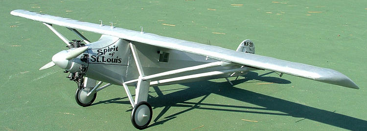
Guillow's 1/16 Spirit of St. Louis
| KIT #: | 807 |
| PRICE: | $46.59 MSRP |
| DECALS: | One option |
| REVIEWER: | Paul Oberle |
| NOTES: | Balsa, tissue and plastic multimedia kit |
| INTRODUCTION |
Some time
back, in one of my rare contributions to a discussion thread at Modeling
Madness, I made note of my newly acquired balsa kit.
At that time I also remarked that the interests at MM seemed to be
in plastic model kits and not much else.
Without letting too much time go by, our Administrator rejoined that
nowhere in the site’s policies, philosophies, discussions, etc. was there a
mention that styrene was the rule, or even that it was preferred here at MM.
And, in fact, if someone wanted to make a contribution in another area
then one should do so.
Appropriately chastened, I realized that not only did I have to get on with
building this kit, but now I had motivation to provide a review. First of all, I
have to go on record as having built exactly one other balsa kit in my life.
My initial try was the Wright Flyer.
Not a terrible experience, but certainly not enough to make me a balsa
expert. And as I was about to find
out, this kit was going to be a whole lot different, especially in the amount of
wing and fuselage area needing to be covered.
At any rate, knowing that there are more than a few of you out there who
are proficient with these kits, I’ll offer this write-up as more my experience
with the
 build rather than a critique of the kit.
Maybe you’ll be able to relate.
Maybe you can show me the error of my ways.
For those who have never tried a balsa kit, I hope this won’t scare you
away.
build rather than a critique of the kit.
Maybe you’ll be able to relate.
Maybe you can show me the error of my ways.
For those who have never tried a balsa kit, I hope this won’t scare you
away.
With
regard to the kit itself, I’ve always liked the
Spirit of
Not long
after visiting the Internet for helpful hints, I made a basic decision to build
this right out of the box. What I found on the Net left me more than a little
stunned by what some really talented people can do with this model.
Some folks had essentially thrown the kit parts away but kept the plans
and built a fresh model from scratch. Some modelers had opted for thin balsa
sheets rather than tissue for the skin.
(This technique was suggested by several here at MM.)
I found a Spirit with a
detailed interior with an instrument panel and flight controls - even a wicker
seat for Lindy to sit in. I saw a miniaturized Whirlwind engine super detailed
down to ignition wires. New props had been fashioned for some models; one was
machined from stock aluminum; another was freshly cast in resin. Another kit had
cast resin cylinders for the engine and wheel hubs drilled out and replaced with
plastic sheet. In several cases,
the plastic engine cowling from the kit had been tossed and replaced with
aluminum sheeting cut to size and then burnished for real – just a smaller
rendition. These were really some
show stopping prize winners.
It
occurred to me then that by comparison, my airplane might look very much like
Charlie Brown’s Christmas tree.
Not to
panic, however. What I do in times
like these is invoke the spirit of one o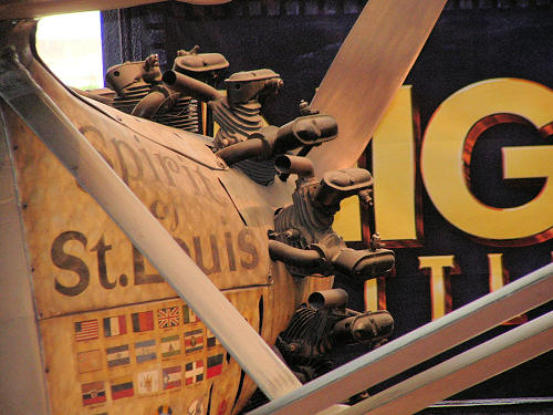 f my cinematic heroes of the distant
past, Inspector Harry Callahan. In the movie, Magnum Force, Dirty Harry
utters the unforgettable line, “A man’s got to know his limitations.”
I have adopted this philosophy as my mantra and guiding light – and not
just for building model airplanes.
f my cinematic heroes of the distant
past, Inspector Harry Callahan. In the movie, Magnum Force, Dirty Harry
utters the unforgettable line, “A man’s got to know his limitations.”
I have adopted this philosophy as my mantra and guiding light – and not
just for building model airplanes.
So then I
was resolved. I was, in fact, not
going to bite off more than I could chew with this project.
Everything I need for a decent plane is going to be right in the box.
This is going to be enough of a challenge as it is.
As one
might imagine, there is an absolute mountain of information about Lindbergh, the
airplane and the flight. Histories
abound on different websites; books are readily available (Lindbergh himself
wrote a couple accounts of the flight).
There are bios and opinion pieces everywhere regarding Lindbergh and his
politics. There are also a couple
of movies. If you’re so inclined,
you can take in Billy Wilder’s 1957 epic entitled (what else)
The Spirit of St. Louis
starring Jimmy Stewart (at age 48 playing Lindbergh at 25).
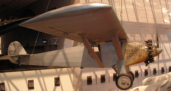
And - if
you’re as lucky as I am to live close by, you can go down to the Smithsonian in
Washington, D.C. and see the real deal hanging from the ceiling of the Air and
Space Museum. That’s pretty neat.
For a
concise history, one has to go no farther than right here at Modeling Madness.
Bill Michaels provided an excellent write-up as part of his kit preview
back in 2006 for the Revell 1/48 offering.
Here is the citation for your convenience.
http://www.modelingmadness.com/reviews/civil/previews/michaelssoslpreview.htm
 For those
of you who can’t tear yourselves away, here is the brief history as it appears
on the plaque in front of the Spirit
at the Smithsonian:
For those
of you who can’t tear yourselves away, here is the brief history as it appears
on the plaque in front of the Spirit
at the Smithsonian:
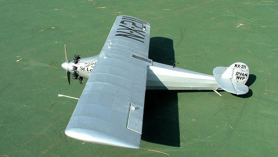
Ryan NYP
Spirit of
First Nonstop Solo Transatlantic
Flight
“On May
21, 1927, Charles A. Lindbergh completed the first solo nonstop transatlantic
flight in history, flying his Ryan NYP
Spirit of St. Louis, 5,810 kilometers (3,610 miles) between Roosevelt Field
on Long Island, New York and Paris, France, in 33 hours, 30 minutes.
With this flight, Lindbergh won the $25,000 prize offered by New York
hotel owner Raymond Ortieg to the first aviator to fly an aircraft directly
across the Atlantic between New York and Paris.
When he landed at Le Bourget Field in Paris, Lindbergh became a world
hero who would remain in the public eye for decades.
The
aftermath of the flight was the “Lindbergh Boom” in aviation: aircraft industry
stocks rose in value and interest in flying skyrocketed.
Lindbergh’s subsequent U.S .and Central and South American tours in the
Spirit demonstrated the potential of
the airplane as a safe, reliable mode of transportation.”
| THE KIT |
The kit
comes in a big 20 inch box that has a surprising amount of heft to it.
That’s because there’s a lot of stuff in there.
The plane itself is big - a 34 1/2 inch wingspan - so a fair amount of
building material is supplied. Most
of your balsa needs are taken care of by individual sheets coded for a specific
part of the build (e.g. the fuselage, the wing, the rudder, etc.). The
individual pieces have been die-cut for you.
The sheets contain the larger pieces for structural members like
bulkheads and wing ribs. Also
supplied is what they call ‘spaghetti’.
Don’t think of a mound of hot pasta, but rather the pre-cooked brittle
version that comes
 from the deli.
Balsa sheets have been sawn into long strips of varying dimensions (e.g.
1/16X1/8 inch, 1/16X1/16 inch). The
dimensional strips have to be cut away from the block of spaghetti as you use
them. The 1/16 pieces were used
primarily as horizontal stringers to build the front of the fuselage and for
wing spars.
from the deli.
Balsa sheets have been sawn into long strips of varying dimensions (e.g.
1/16X1/8 inch, 1/16X1/16 inch). The
dimensional strips have to be cut away from the block of spaghetti as you use
them. The 1/16 pieces were used
primarily as horizontal stringers to build the front of the fuselage and for
wing spars.
Also in
the box – tissue paper to hang skin on all the surfaces; steel wire of different
gauges for the landing gear and other structural hook-ups; vac-formed plastic
for the engine cowling, wingtips, prop and other details; a nice sheet of
decals, too. Plastic wheels are included as is a sheet of clear acetate to be
used for the windows and skylight.
Detailed plans are provided. You’ll have
two big sheets by the time you cut them into usable sizes.
In reality they’re templates that you use for constructing the main
sections of the plane.
The
Guillow’s folks have concocted this kit with the basic notion that it will fly.
The plans let you build a dihedral into the wing if you want to launch it
into the wild blue yonder. (The wing on the real
Spirit was flat.)
They supply additional materials for strengthening the frame to accept a
gas engine or tensioned for a rubber band motor.
They give you equipment to hook up hand held line controls so you fly it
from the ground. Also included is a light-weight prop. They even supply a lump
of clay that can be used to distribute weight in strategic areas for balance.
The kit is very well stocked. True, there are no duplicate plastic pieces, but there is more than sufficient balsa and tissue to accommodate a normal amount of screw-ups and do-overs. For the more egregious and/or repetitive screw-ups that require even more do-overs, you may have to resupply at your local hobby store. I know I did.
| CONSTRUCTION |
Tools and
Equipment
For
starters you must have a decent surface on which to work; a building board, if
you will. There are commercial
items available, but a cost effective and user-friendly item is foam-core board.
They come in varying thicknesses, but all you need is something that will
hold a straight pin. The plan – the template really – is tacked down flat to the
board. You’ll then need to cover it
with something akin to Saran Wrap (the filmy plastic stuff).
Glues don’t necessarily stick to Saran Wrap, so this avoids your gluing
your balsa pieces to the paper plan and ruining it.
Using the template as a guide, you pin your balsa pieces directly to the
board on top of the template, gluing pieces together as necessary as you move
along. By the way, you need lots
and lots of straight pins.
Cutting
and shaping is the name of the game.
You need the biggest multi-pack of No. 11 X-acto blades you can find.
Also necessary is a large supply of single edged razor blades.
Optional, but very handy, is a razor saw and mini miter box.
I used my pin vise to drill any number of holes.
Lots of sandpaper in a variety of grits is required.
Glue,
glue and more glue. I’m not sure if
there was any type of glue not used in this build. I used white glue, yellow
glue, fast setting CA, slow setting CA.
I used a two part epoxy, plastic tube glue and plastic liquid glue.
A glue stick also got some use.
Loads of
hand tools from my tool box were employed:
several different pliers, tack hammer, measuring tapes & rules.
I even put my bench vise to use.
I used a compass, protractor and straight edge. Scissors came in handy,
as did clothes pins to act as clamps.
 Finally,
I shouldn’t omit the electric rotary tool.
That item proved invaluable in cutting wire and also for boring and
shaping some plastic pieces. I’d
still be plugging away at the workbench if I didn’t have it.
Finally,
I shouldn’t omit the electric rotary tool.
That item proved invaluable in cutting wire and also for boring and
shaping some plastic pieces. I’d
still be plugging away at the workbench if I didn’t have it.
Consider
the plans. If your only modeling
experience has been with mainstream plastic kits, you’re probably used to seeing
a set of numbered instructions that lead you through a, more or less, logical
sequence of assembly. Well, this is
a little bit different. You can
start with the wing. You can start
with the fuselage. You can start
wherever you want. The real
construction is in the plane components. In fact, actual assembly of the parts
into the final product is relegated to a tiny narrative in the plans with an
even tinier blow-up showing the assembly.
However, by the time you get there, you’ll be intimate with all the
details and know where everything goes.
Most
model kit instructions say “Please read the instructions.”
Well, here they’re not kidding.
While the plans lay out the location of each individual piece, they also
provide lots of side notes with special instructions along with blow-ups of more
complicated areas of construction.
There are little details depicted that, if you ignore them or miss them early
on, they’ll come back to bite you later.
It’s a good idea to get out your yellow highlighter or red pen and put it
to use early and often.
The Build
Each
balsa piece has to be removed carefully from its background sheet.
Just because the outline has been pre-cut, doesn’t mean you can pop these
out with your thumbs. Sometimes the
cut hasn’t gone all the way through, and other times the piece is just too thin
or delicate. You’re also going to
have to ‘dress’ each piece, removing nubs and splinters and providing sanding on
some rough edges. All in all, the
pre-cut pieces are great. I can’t
imagine the olden days when pieces had to be sawed or carved individually.
Fuselage
For no
special reason I started with the fuselage. With the initial perimeter pieces
tacked down, you have the central axis of the airplane (i.e. lengthwise through
the middle of the fuselage) outlined.
From here you build out the left side of the fuselage by adding half a
bulkhead at a time making sure it stays perpendicular to your central axis.
You then add a keel to the side to stiffen the whole section.
Upon completion, this half fuselage is removed from the building board
and construction commences on the right side.
The principal concern here is keeping your right-side bulkhead half on
the same plane as its mate on the left side.
The glue stick came in handy as a couple of 1/16 inch scraps were
temporarily glued to the left half bulkhead with one edge hanging out as a guide
and glue surface for the right side half to match up.
 Early on,
I opted to build in a moveable door rather than just penning the outline of the
door onto the fuselage. The door
frame was prepared on the template using the 1/16 inch strips.
The door, however, has to be curved top to bottom to fit the rounded
contour of the fuselage. This is
accomplished by soaking the completed door frame in water.
While still wet, it is placed over some dimensional ‘risers’, the largest
of which is placed across the middle of the door.
The top and bottom of the door are then pinned down to the work board.
When the wood dries you’ll have your permanent curve to the door.
Early on,
I opted to build in a moveable door rather than just penning the outline of the
door onto the fuselage. The door
frame was prepared on the template using the 1/16 inch strips.
The door, however, has to be curved top to bottom to fit the rounded
contour of the fuselage. This is
accomplished by soaking the completed door frame in water.
While still wet, it is placed over some dimensional ‘risers’, the largest
of which is placed across the middle of the door.
The top and bottom of the door are then pinned down to the work board.
When the wood dries you’ll have your permanent curve to the door.
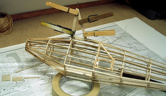
To shape
the fuselage, 3/8 inch stringers are attached to the bulkheads.
The fast set CA glue was most useful here.
Since the fuselage tapers from front to rear, the stringers have to bend
somewhat at each bulkhead. Starting
at the first bulkhead, the fast set glue grabbed the stringer and set fast
enough that you could move on to the second, third, etc. bulkhead, accommodating
the bends and really not slowing down.
You get to the rear of the fuselage and snip off any excess stringer. Go
back to the front and start your second stringer.
Then repeat, repeat, repeat.
Before
all the stringers are all in place, you’re going to have to address the landing
gear. Again, since the finished
model is supposed to fly….and ultimately land….the Guillow’s folks want landing
gear that can take a beating. In
lieu of stronger plywood, the kit supplies a stiff vinyl.
Here again, pieces have been already die cut for you.
And that’s a good thing since this stuff is tough to cut.
Parts to form a cradle for the 1/16 inch landing gear wire are glued to
the forward bulkhead. This is
where the two-part epoxy was recommended for a super tight bond.
The 1/16 inch wire then has to be bent
and manipulated to become the axles and the struts for the landing gear.
 I have to
add a word here about bending wire.
To be good at this, it will be necessary to make a pact with Satan.
I found it that frustrating.
First of all, 1/16 inch may not sound like much, but that steel wire is a bugger
to bend. My wire bending technique
is to drive a nail into a largish piece of plywood. I use the nail as the pivot
point for the bend. With a pair of
pliers in each hand, and the wire flat on the plywood, I bend away, taking the
wire back to the template after each little tug to check if I’m getting close to
the appropriate angle. After
following that routine umpteen times and getting it where I want it, I move on
the second bend. I get the exact
mark and start a new reverse angle.
But upon checking back with the template, this new bend isn’t exactly where I
want it. What the….???
The distance between the two angles is just a little too long.
On the second attempt, well, it’s just a little too short.
And guess what? If you try
to un-bend your initial angle and move it a smidge, you’re just asking for more
trouble. The wire doesn’t un-bend
without leaving a noticeable kink.
So then, how many angles are needed in this piece of wire? Only four?
Might have just as well been forty.
In addition, it’s a hot, humid night.
I’m working on the floor of my garage.
With my head down, sweat balls are dripping onto the inside of my
glasses. I’m looking through a
goldfish bowl. I’m fairly
miserable. Finally, after
much blood, sweat and tears I get the wire bent to where I want it. I lay it on
the template for a final look and realize that one end is up in the air.
It doesn’t lay flat anymore.
Now I’ve lost the flat axis I started with.
I have to
add a word here about bending wire.
To be good at this, it will be necessary to make a pact with Satan.
I found it that frustrating.
First of all, 1/16 inch may not sound like much, but that steel wire is a bugger
to bend. My wire bending technique
is to drive a nail into a largish piece of plywood. I use the nail as the pivot
point for the bend. With a pair of
pliers in each hand, and the wire flat on the plywood, I bend away, taking the
wire back to the template after each little tug to check if I’m getting close to
the appropriate angle. After
following that routine umpteen times and getting it where I want it, I move on
the second bend. I get the exact
mark and start a new reverse angle.
But upon checking back with the template, this new bend isn’t exactly where I
want it. What the….???
The distance between the two angles is just a little too long.
On the second attempt, well, it’s just a little too short.
And guess what? If you try
to un-bend your initial angle and move it a smidge, you’re just asking for more
trouble. The wire doesn’t un-bend
without leaving a noticeable kink.
So then, how many angles are needed in this piece of wire? Only four?
Might have just as well been forty.
In addition, it’s a hot, humid night.
I’m working on the floor of my garage.
With my head down, sweat balls are dripping onto the inside of my
glasses. I’m looking through a
goldfish bowl. I’m fairly
miserable. Finally, after
much blood, sweat and tears I get the wire bent to where I want it. I lay it on
the template for a final look and realize that one end is up in the air.
It doesn’t lay flat anymore.
Now I’ve lost the flat axis I started with.
“B-R-R-I-N-N-G-G-G”, “B-R-R-I-N-N-G-G-G”
(Telephone ringing sound)
Satan:
“Hello. This is Hell.”
Paul:
“Hi, there. Is this Mr.
Satan?”
S:
“Why, yes it is.”
P:
“Hi, this is Paul.”
S:
“Good to hear from you, Paul.
Can I put you on hold for a moment?”
P:
“Sure. No problem.”
This point in the build is also where
the first of many adventures in plastic begins. I have no room to be critical,
but if there’s a red-headed stepchild in this kit, it’s the plastic.
I had never worked with vac-plastic before, but thanks to some good
advice obtained here at MM, the cutting and sanding was a breeze.
I suppose, however, that if you’ve built plastic models all your life,
you have expectations that parts will fit reasonably well; for instance, that
halves will mate up. Even when
filler putty is needed, you get pretty close to a finished surface.
Not so much here, though.
The cowling was formed by two (top and bottom) clamshell shaped pieces.
They seemed fine after cutting them from the sheet, but the plans said
that the top was to overlap the bottom by 1/16 inch.
In reality there was a 1/16 inch gap between the two halves. Also, the
two pieces were to reach horizontally from the nose to the first major bulkhead
which was to be a glue surface.
Well, they fell short there as well. Not really fatal flaws; I added
 filler
pieces to make up for the gaps and to give me a place to glue the cowling down.
I then broke out the putty and started sanding.
filler
pieces to make up for the gaps and to give me a place to glue the cowling down.
I then broke out the putty and started sanding.
The cowling also provided dimples as
locators for the nine engine cylinders.
They were close, but sadly, no cigar.
I had to give myself a geometry refresher course to see if I could get
those nine cylinders to look a bit more symmetrical going around the nose.
I located new points and then bored larger holes of sufficient diameter
to accept the cylinders.
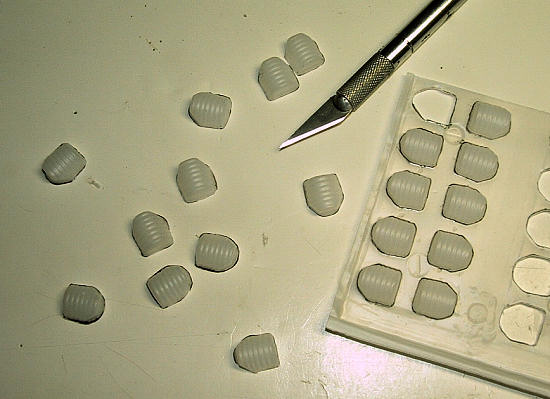
The
cylinders themselves provide another case in point.
After cutting 18 little halves from the plastic sheet, you pair them
together and come to realize that no two are alike.
They are all in varying stages of roundness.
The best one is close to being round.
The worst one looks like Aunt Dorothy sat on it.
At any rate, I did try to detail these guys a little bit by adding rocker
boxes that I shaped from balsa and exhaust and intake pipes fashioned from 14
gauge electrical wire. Crude, but
better than what I started with.
Pushrods might get added later. (Frankly, it’s more than I want to take on right
now.)
My final
rant regarding the plastic has to do with the prop.
Here again were two halves that had to be joined.
The blade on one half was ridiculously shorter than the other.
Overall there were so many gaps in the seams you had enough daylight to
read by. I actually went out and
bought a wooden prop for an RC aircraft that I thought I could sand into shape.
I realized pretty quickly that was going
to prove to be more work than I needed.
I bit the bullet and went back to the kit plastic.
Putty… sand. Putty…sand.
Repeat. Repeat.
Repeat.
Tail
Feathers
The tail
assembly was the next. These parts:
rudder, tail fin, stabilizers, elevators, weren’t too tricky; just another
exercise in templates, straight pins and glue.
The kit gives you the option of having moveable control surfaces.
Of course, you have to build them in if the plane were to be a flying
model. For the static model the
plans suggested using a marker pen to outline the rudder, elevators and
ailerons. That technique was also
recommended for the door. Well, in
for a penny, in for a pound. Since
I was in it this far, I might as well go for the moveable surfaces.
To create a hinge for the moveable pieces, the plan recommends cutting a
tiny rectangle from the clear acetate sheet supplied in the kit.
In some instances the hinge is sandwiched between two framing pieces and
glued into place. In other cases,
you have to carve out a slit to accept one edge of the hinge.
Since these moveable surfaces (e.g. rudder to tail fin) are going to be
attached to each other, you need to pay attention to alignment since a pocket
will be needed for the hinge on the corresponding piece.
Wing
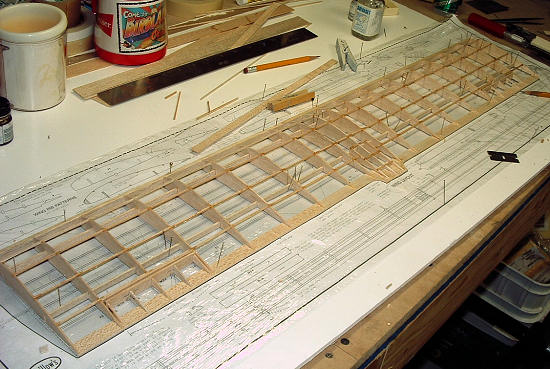 Construction of the skeleton for the wing went relatively easily. After laying
down the leading and trailing edges and two structural spars, the wing ribs were
added one by one. There is about an
acre of wing here so this takes a while.
The 1/16 inch stringers are then added horizontally across the ribs.
The problematic part of the wing construction is sanding down the leading
edge. The original dimension of
this piece of balsa is 3/16X3/8 inch.
You need to sand away probably a third of it to get the profile shaped to
where you want it. Since the whole wing is 34 inches long it is extremely
unwieldy to handle. You have to
figure out a way to hold it and sand at the same time.
My method made it look like I was playing the washboard in a jug band.
I still wound up sticking my thumb through at least five different
stringers and had to go back and splice in new pieces.
Adding the plastic wing tips was the final step.
I have to report that they were the best of all the plastic pieces.
No problems in cutting or installing.
Construction of the skeleton for the wing went relatively easily. After laying
down the leading and trailing edges and two structural spars, the wing ribs were
added one by one. There is about an
acre of wing here so this takes a while.
The 1/16 inch stringers are then added horizontally across the ribs.
The problematic part of the wing construction is sanding down the leading
edge. The original dimension of
this piece of balsa is 3/16X3/8 inch.
You need to sand away probably a third of it to get the profile shaped to
where you want it. Since the whole wing is 34 inches long it is extremely
unwieldy to handle. You have to
figure out a way to hold it and sand at the same time.
My method made it look like I was playing the washboard in a jug band.
I still wound up sticking my thumb through at least five different
stringers and had to go back and splice in new pieces.
Adding the plastic wing tips was the final step.
I have to report that they were the best of all the plastic pieces.
No problems in cutting or installing.
Paper
Hanging
After
completing all the shaping and sanding and gluing of the balsa pieces, I was
actually looking forward to hanging the tissue paper on the frame.
Little did I know that this was to be another descent into modeling hell.
The time honored substance used to attach and finish tissue is dope.
I had tried this previously on my Flyer model and didn’t have much
success. It didn’t seem to have
enough stick-um to it. As an
alternative to dope, Guillow’s and others recommend a solution of white glue
diluted with water (ratio ranging from 50-50 to 70-30).
Since this worked for me before, I followed Nancy Reagan’s advice and
just said “No” to the dope and went with the white glue. The procedure is to
apply a coat of the white glue solution on all the wood surfaces to act as a
sealant. After that dries you
lightly sand and recoat with the same solution.
While it’s still wet you can begin to hang the paper.
The instructions recommended covering a large area with only a few pieces
of tissue (e.g. two pieces only for one side of the wing).
On my first attempt at this I got very uneven adhesion.
I suspect I didn’t use enough glue in certain spots and it dried before
the paper touched down. I also
found the tissue to be rather unforgiving in trying to re-glue those areas that
weren’t tacked down. If I made a
tiny cut on top of a wing rib to inject a bit of glue, it eventually just sagged
and looked fairly pitiful. Oh well,
let’s re-do. On the next
go-round I used smaller pieces of tissue (e.g. six pieces to cover the wing this
time). I had a bit more success
doing it that way.
Once the
paper adheres, it gets a spritz of water.
Then you walk away until it dries.
As the water evaporates, the tissue contracts taking out any wrinkles
that might have been there initially.
You wind up with a taut surface stretched over the frame.
So far, so good. At
this point the surface has to be sealed to close up all those pores in the
tissue. Here again, if you’re not
using dope, the same white glue solution is used.
I used a wide brush and, applying in one direction, covered the tissue.
The whole thing then needs time to dry.
These
intervals set you free to work on some other part of the plane or just call it a
night and go to bed. Invariably,
when I chose the latter and came back for a look the next morning, I felt like
Forrest Gump with his box of chocolates.
I never knew what I was gonna get. I had a heck of a time with the curved
edges, especially the outer edges on the stabilizer, elevators and rudder.
I couldn’t avoid the paper puckering and leaving unsightly wrinkles.
Also on these particular parts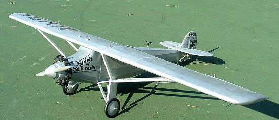 , the framing pieces were fairly wide.
I must have applied too much solution and saturated the tissue to where
it was weighed down and stuck flat to those surfaces.
It didn’t leave me the crisp trailing edge I was looking for.
Oh well, let’s re-do.
, the framing pieces were fairly wide.
I must have applied too much solution and saturated the tissue to where
it was weighed down and stuck flat to those surfaces.
It didn’t leave me the crisp trailing edge I was looking for.
Oh well, let’s re-do.
Eventually I took the approach of gluing the top surfaces (leading edge and ribs) but as I got to the trailing edge I would apply glue to the opposite side of the frame only, pulling the paper taut and wrapping it around. That seemed to get my puckers removed and gave me a much neater edge. I wish I could say I found a technique to solve all my problems, but there seemed to be many, many gremlins at work.
| COLORS & MARKINGS |
Painting
Painting
the airplane wasn’t a step in and of itself.
It was more a continuation of finishing the tissue.
Given the large surface areas, I decided to go the spray can route.
I wound up with a Krylon aluminum that I selected only because I liked
the color…. metallic, but not too shiny.
After making a few passes and getting what I thought was good coverage, I
realized it wasn’t. When I held it
up to the ceiling light, well, …. I could see the ceiling light.
So what’s the deal here?
Does it need more white glue to seal the tissue?
What will the glue do on top of the paint? Let’s give that a try.
That doesn’t work. Let’s
re-do.
What
ensued were very many re-dos. I would cut out the bad section with the X-acto
blade and then scrape and sand the residual paper and glue off the spars and
ribs. Then I’d measure and cut a
piece of tissue to fit, and patch on this new replacement piece.
I’d apply my white glue solution and let it dry.
I’d apply paint and let it dry.
I just could not, however, beat the odds of having another sag or wrinkle
appear. I wound up having to
replace a bit of the skin on the fuselage, but compared to the wing, that was a
walk in the park. I replaced
probably three quarters of the tissue on both sides of the wing at least once;
some sections twice.
One
evening I found myself examining a section of wing I didn’t particularly like.
I knew I had replaced it at least once before. As I picked up the X-acto
blade to start another re-do, I felt a tap on my shoulder.
Thankfully, it wasn’t Satan.
It was, however, Inspector Callahan.
Harry noted that this was all going nowhere fast and suggested that
perhaps I had reached the limit of my limitations.
When he asked, “Do you feel lucky?” I felt that I should take his message
to heart. Let’s wrap this thing up.
 From the
beginning I had wanted to do something to set the cowling off since the
burnished whorls on the real thing give it such a distinctive look.
But since I wasn’t going the route of real aluminum sheeting, what’s out
there for alternatives? I
considered a free-hand paint job, but felt pretty quickly that would prove
disastrous. One day, while cruising
the aisles in the paint department at Home Depot, I came upon a product called
‘Hammered’, offered in a spray by the Rust-Oleum people.
(‘Hammered’…..what a great name!
I was so much looking forward to quitting for the night and getting
myself just that way.) The spray is for outdoor use for porch railings, lamp
posts and such and leaves a textured finish that looks……well ……hammered.
I thought that this could be the answer.
I masked off the back of the fuselage and gave the cowling a couple of
coats of ‘Hammered’. It did leave a
texture, but nothing overly dramatic. It was enough to differentiate it from the
rest of the skin, plus it was a shade different color.
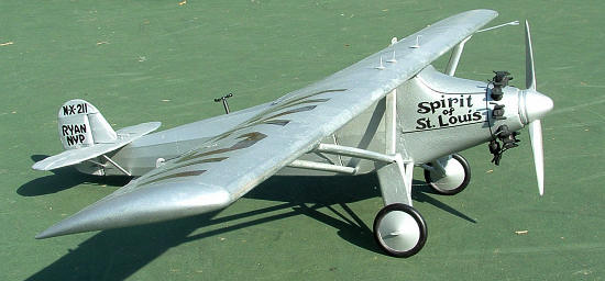
I then added some Formaline art tape to the cowling to serve as the panel
lines. I was as happy as a clam.
From the
beginning I had wanted to do something to set the cowling off since the
burnished whorls on the real thing give it such a distinctive look.
But since I wasn’t going the route of real aluminum sheeting, what’s out
there for alternatives? I
considered a free-hand paint job, but felt pretty quickly that would prove
disastrous. One day, while cruising
the aisles in the paint department at Home Depot, I came upon a product called
‘Hammered’, offered in a spray by the Rust-Oleum people.
(‘Hammered’…..what a great name!
I was so much looking forward to quitting for the night and getting
myself just that way.) The spray is for outdoor use for porch railings, lamp
posts and such and leaves a textured finish that looks……well ……hammered.
I thought that this could be the answer.
I masked off the back of the fuselage and gave the cowling a couple of
coats of ‘Hammered’. It did leave a
texture, but nothing overly dramatic. It was enough to differentiate it from the
rest of the skin, plus it was a shade different color.
I then added some Formaline art tape to the cowling to serve as the panel
lines. I was as happy as a clam.
The tires
were painted Model Master black; the prop was done in Model Master steel.
The engine cylinders were done in Testor’s (the little square bottle)
flat black; touchups everywhere were done in Testor’s aluminum.
Taking a
tip from the pages of Modeling Madness I gave the entire plane a coat of
Future floor wax. I didn’t know
what to expect, but I knew I needed a surface for the decals.
No harm, no foul. The Future
went on fine. Nothing eroded or
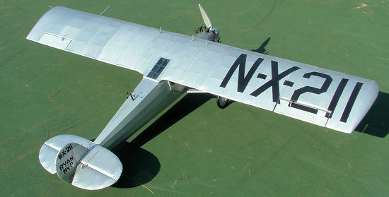
dissolved.
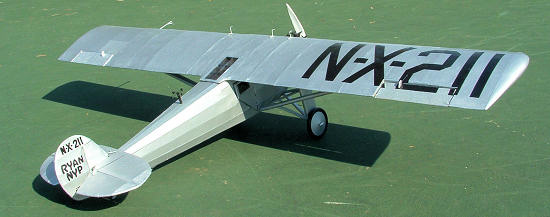
The decals are a nice asset to this kit. Actually, there aren’t that many, but in this scale they cover a lot of area. The registration numbers are so large that I didn’t debate for a second to cut each numeral out separately from the backing. The cowling and rudder decals went on without a hitch.
| FINAL CONSTRUCTION |
The last
real construction to do on the kit was to prepare the wing struts.
Again for strength, the kit opts for the 1/16 inch vinyl which is
sandwiched between two layers of balsa.
Sanding renews in earnest as this boxy section needs to be taken down to
a streamlined profile. Here also, I
had to revisit my favorite pastime of wire bending.
A thinner gauge wire is used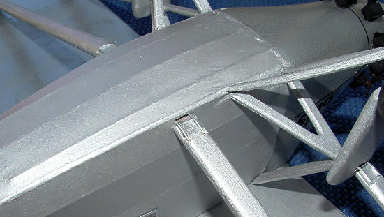 here so cursing can be kept to a minimum.
A U-shaped affair is fashioned to form what is essentially a tab that is
attached to either end of the strut.
The tabs on one end are inserted into pockets under the wing; the tabs on
the other end go into pockets in the fuselage and landing gear.
here so cursing can be kept to a minimum.
A U-shaped affair is fashioned to form what is essentially a tab that is
attached to either end of the strut.
The tabs on one end are inserted into pockets under the wing; the tabs on
the other end go into pockets in the fuselage and landing gear.
With the
stabilizer on and the rudder affixed, the wing then gets glued down.
The struts are inserted. The
wheels go on their wire axles and……Voila!......it looks very much like an
airplane.
About
this time I was thinking how nice it would be to go to a plastic sprue and nip
off some tiny, highly detailed piece and just glue it on the model to finish it
off. But we can’t get all
delusional here. This is a balsa
kit. If you want detail, you build
it. Individual items yet to be
added included the pitot tube, the carburetor, aileron & elevator horns, gas
tank vents and that curious wind compass generator that goes atop the fuselage.
The pitot
tube was fashioned from a length of 1/16 inch balsa sanded down to a thin reed.
The lower portion of the tube with the curved section was accomplished
through soaking the wood and bending it before it dried.
I cut a small section out of the arc and glued it to the main piece.
The carburetor is a conglomeration of balsa discs and square stock all
glued together with liberal amounts of putty applied.
The control surface horns were shaped from scrap pieces and drilled to
accept the control cable. The tear drop gas vents were shaped from balsa scraps
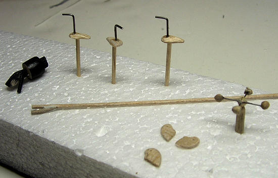
with a piece of wire added for the actual vent tube. The wind generator was
probably the most challenging of the details.
To form the cups I used a hardwood dowel that came with the kit.
I tapered one end of the dowel and blunted it a bit by sanding a softer
bowl shape to it. When I was
reasonably happy I took the dowel to the miter box and sawed off my rounded cup.
Then I did that three more times.
I drilled a hole in the side of each little cup to accept a 0.03 inch
wire and attached it with CA. Two
cups were attached to either end of a 5/8 inch length of wire.
I made two of these and crossed them at a right angle.
I sandwiched the junction between some scrap balsa and sanded it into a
hub. I then attached that to a
pedestal for positioning on top of the plane.
Lest I forget, my last detail was to add a little piece of balsa and
cardboard to the side of the fuselage to represent the periscope.
You know
what? We’re there.
| CONCLUSIONS |
Not
everyone’s cup of tea, to be sure, but maybe every modeler should have at least
one balsa kit in his or her portfolio.
It may be a throwback, but there is still plenty of interest in building
these kits and not just from the RC crowd.
I think they offer loads of challenges, but in the hands of a competent
and patient modeler (not using me as an example) some really great results can
be 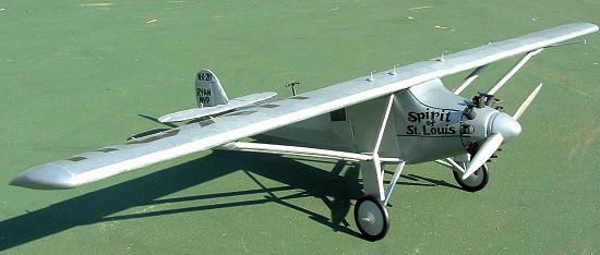 achieved. Comparison to an
injection molded plastic kit is probably inevitable, but I really think that
should be avoided. A balsa kit just
happens to be a different species altogether.
To be certain, it is not a weekend project.
And in reality, you don’t want to rush it. Half the fun (really) is in
getting there. I actually did use
it as my chance to unwind in the evenings by retiring to the garage workbench
with my favorite CD and favorite beverage(s).
I got a nice sense of satisfaction watching this thing progress over the
months.
achieved. Comparison to an
injection molded plastic kit is probably inevitable, but I really think that
should be avoided. A balsa kit just
happens to be a different species altogether.
To be certain, it is not a weekend project.
And in reality, you don’t want to rush it. Half the fun (really) is in
getting there. I actually did use
it as my chance to unwind in the evenings by retiring to the garage workbench
with my favorite CD and favorite beverage(s).
I got a nice sense of satisfaction watching this thing progress over the
months.
As with
anything, practice makes perfect. I
certainly know the areas where I need to improve.
I also need to ask myself about future modeling initiatives.
Do I want to invest the time and effort into new and different skills
like casting resin parts or turning pieces on a mini-lathe?
Hmmmm…….food for thought.
We’ll have to see.
| REFERENCES |
Berg, A.
Scott, Lindbergh, (New York: G.P.
Putnam’s Sons, 1998)*
Charles
Lindbergh, an American Aviator
http://charleslindbergh.com
Guillow’s
Model Builder Forum
http://balsamodels.com
Lederer,
Charles, The Spirit of St. Louis,
motion picture, directed by Billy Wilder, filmed at Santa Maria Public Airport,
Santa Maria, California, produced by Leland Heyward, 1957
Smithsonian National Air and Space Museum on the National Mall, Washington, D.C.
Virtual
Aerodrome
http://www.virtualaerodrome.com
Wikipedia
http://en.wikipedia.org/wiki/Spirit_of_St._Louis
*(If you
have even a passing interest in Lindbergh, Berg’s book is a must-read.
Mr. Berg won the Pulitzer for Biography or Autobiography for this effort.
Since it was published in 1998, the book is missing the later revelations
about Lindbergh’s additional secret families in Europe, but that’s hardly a
concern. Just a matter of time
marching on. I heartily recommend
the book.)
December 2009
Copyright ModelingMadness.com. All rights reserved. No reproduction without express permission.
If you would like your product reviewed fairly and quickly, please contact the editor or see other details in the Note to Contributors.