| HISTORY |
Airfix 1/72 Fairey Rotodyne
| KIT #: | 04002 |
| PRICE: | AU $16.65 |
| DECALS: | One option |
| REVIEWER: | Steven Pietrobon |
| NOTES: | An oldie but a goodie |
| HISTORY |
The Rotodyne is a strange looking beast, with both helicopter blades and
propellers. However, this is no normal helicopter, its what is called a
gyrodyne. Kerosene and air are pumped to small rocket motors at the end
of the blades, which turn the rotor, providing vertical lift. Since the rotor
itself provides the turning force, there is no torque against the aircraft body,
like in a normal helicopter, so no tail rotor is required. As altitude is
gained, the propellers provide more forward thrust, providing lift over the
stubby wings, as well as lift from the rotor. After a minute, the rocket motors
are turned off, with the rotor operating as an autogyro, providing 65% of
the lift. In an autogyro, the pitch of the blades is angled upwards, instead of
backwards as in a normal helicopter.
 The autogyro mode allows much faster speeds
compared to a normal helicopter, which is limited to the stalling angles of the
retreating rotor blade. There is also increased safety as due to the rotating
blades, they continue to provide lift until landing, unlike a normal wing which
will stall below a certain speed.
The autogyro mode allows much faster speeds
compared to a normal helicopter, which is limited to the stalling angles of the
retreating rotor blade. There is also increased safety as due to the rotating
blades, they continue to provide lift until landing, unlike a normal wing which
will stall below a certain speed.
The Rotodyne first flew on 6 November 1957, with transition to autogyro mode occurring only four months later on 10 April 1958. The Rotodyne used two Napier Eland NE.13 motors. These engines were designed to have an initial power of 2240 kW (3000 hp) each, eventually reaching 3130 kW (4200 hp). However, this power was never achieved, reaching only 2090 kW (2805 hp). This was achieved by increasing fuel mixture, which resulted in high fuel consumption and an increased noise level. Despite the reduced power, the Rotodyne achieved a record speed of 307.2 km/h (190.9 mph) over a 100 km course in the new E.2 Convertiplane category on 5 January 1959. This led to much interest, with New York Airways signing a letter of intent and Kaman Aircraft obtaining a license to build Rotodynes in the US.
Unfortunately, Fairey Aviation had been forced by the government to be acquired by Westland Aircraft on 2 May 1960. The lack of interest by the military and Westland along with perceived noise and fuel consumption problems, led to Rotodyne being cancelled on 28 February 1962. The noise and fuel problems could have been remedied with a more efficient engine along with other improvements, that at the time had reduced noise levels to 96 dB at 180 m (600 ft).
Here's a comparison between Rotodyne and the V-22 Osprey using information from Wikipedia:
| Rotodyne | V-22 Osprey | |
| Maximum speed (km/h) | 343 | 509 |
| Range (km) | 830 | 1627 |
| Loaded weight (kg) | 15,000 | 21,500 |
| Maximum take-off weight (kg) | 17,000 | 27,400 |
| Engine power (kW) | 2,090 | 4,590 |
| Passengers | 20 | 24 |
We can only speculate as to how the Rotodyne would perform with the same engines as the V-22 Osprey. These have 2,500 kW more power each or a 120% increase!
| THE KIT |
During the late 1950's, the Rotodyne was a popular subject among the kit makers. Airfix released its 1/72 kit in 1959, being only its second Series 4 kit. Frog also issued a cruder 1/72 kit, which hasn't been reissued and is now quite rare, with reportedly only 1500 kits being made. Revell released a very nice kit, but in the strange scale of 1/78. This included a full interior with several passengers, stewardess and luggage! Lincoln released a 1/144 scale kit.
I first built this kit unpainted in the early 1970's. With my return to the
hobby in 2003, I found a local hobby shop had Airfix's 1996
 reissue still on the shelf. On
first inspection, the parts looked quite good, with little flash to be seen. A
closer look though revealed a few scratches and pits in the mould leaving their
mark on the parts. The mould could definitely use a bit of a cleanup. Never the
less, I was quite glad to be able to buy this cheaply.
reissue still on the shelf. On
first inspection, the parts looked quite good, with little flash to be seen. A
closer look though revealed a few scratches and pits in the mould leaving their
mark on the parts. The mould could definitely use a bit of a cleanup. Never the
less, I was quite glad to be able to buy this cheaply.
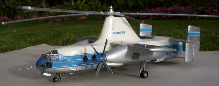
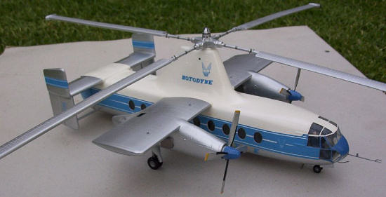
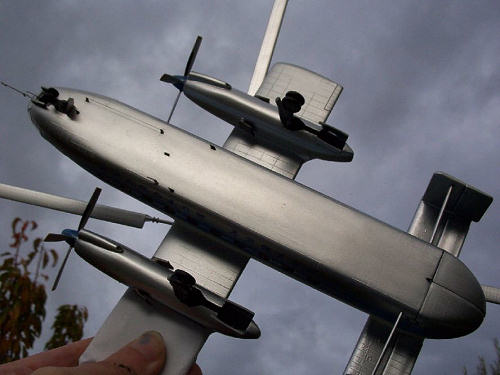
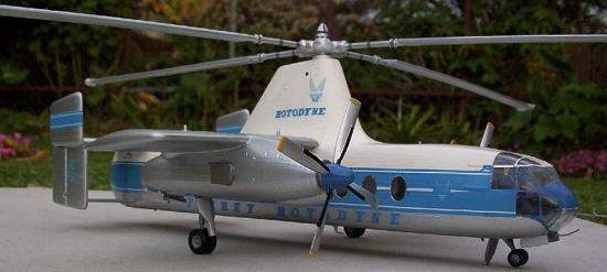
The kit is of the Rotodyne midway through its short life. A latter version included a third fin on the rear fuselage, which the Revell kit has, but the Airfix kit doesn't. You may see some photos of the upper fins of the tailplane at an angle. This is not a different fin, but the same fin being rotated downwards to prevent the rotors hitting them when they are at rest. The Airfix kit has the fins upright, which is a valid configuration on the ground after the rotors have gathered speed and are horizontal. As the kit rotors are horizontal instead of drooped down, then this is OK.
As is usual for kits of this era, the fuselage, wings and tail are proverbially festooned with rivets. Panel lines are of course raised. I don't mind this, but along the alignment pins there were large sink marks at the top and bottom of the fuselage. The inside of the canopy was scratched. An addition to the kit from when I first built it were two control sticks.
The decals looked quite good, with only a small amount of white showing on the military serial number. However, instead of being dark blue, the decals were light blue. Two decals for the instrument panels were included.
| CONSTRUCTION |
Starting with the 20 side windows, these had a concave shape,
causing them to act like lenses. I made the windows flat by sanding them against
a piece of 800 sandpaper on a board, with a bit of water as lubricant. I then
used car polish and a rag to get them crystal clear again. I used the same trick
with the canopy to remove the inside scratch. I glued the windows to the
fuselage using Testors clear drying cement. However, this was not strong enough,
with many windows being easily pushed in. Fortunately, I had left the rear doors
open, so that I could glue them back in, but this was a tricky operation. If I
was to do this again, I would 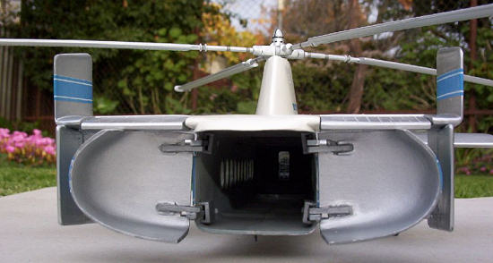 mask the inside edges of the windows before
painting the interior. I would then put the window into the fuselage hole and carefully apply liquid cement around the outside edge of the window.
mask the inside edges of the windows before
painting the interior. I would then put the window into the fuselage hole and carefully apply liquid cement around the outside edge of the window.
My original instructions showed the top rotor head 47 having a small hole, whereas the kit part now had a large hole. This is probably due to the mould being damaged in the pass and then fixed to have a larger hole. The new instructions say to glue the rotor pin 49 to the rotor head, but the old instructions say to glue the rotor pin to the fuselage, which is what I did. I also added a thick piece of plastic card to the hole in 47, drilling out a smaller hole in the middle, to restore the part to its original condition.
To get the control sticks to fit in the interior, I had to drill a hole between the pilots thighs. I found the instrument decals to be a little brittle, with them breaking in a couple of corners. The original instructions mention that weight should be added up front. I used strips of sheet lead to make a 15 g nose weight. This was wrapped in Tamiya tape, painted and superglued behind the cockpit.
I sanded the edges of the alignment pins on the fuselage until I had the top and bottom aligned. Filling in the large sink marks took many applications of filler and paint. I was a bit agressive in sanding the bottom join, leaving a trench along the bottom! I filled this in by liberal application of Humbrol 1 primer. All the filling, sanding and painting resulted in most of the rivets and panel lines disappearing along the top and bottom.
To attach the forward probe, I drilled a hole at the front of the canopy.
After carefully masking the canopy and glueing it on, I noticed that the canopy
framing did not correspond to the Roy Cross painting on the box-art or in my
reference photos. There is quite a difference, so off came the masking and then
sanding off the frame lines. During this, there appeared to be an inside scratch
near the edge I missed, so off came the canopy for this
 to be fixed. With a
calculator and careful measuring, I remasked the canopy and glued it back on,
with the fit being pretty good.
to be fixed. With a
calculator and careful measuring, I remasked the canopy and glued it back on,
with the fit being pretty good.
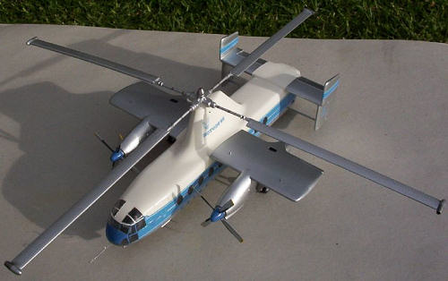
On the port wing, the inside vertical probe (I'm not sure what it is) had broken off. I drilled a hole and superglued a shortened pin in its place. There were some small sink marks on the engine nacelles. These were filled in with putty. I had to do a bit of sanding to the nacelles to make them fit to the wings. I sanded the rivets and panels lines along the bottom of the wing where the engine attaches. After attaching the engines, the propeller assemblies were glue to the engines. With all the handling and sanding, I think I broke off four blades! These were all superglued back on, with a hole drilled into the base of the blade and spinner and a pin attached for extra strength.
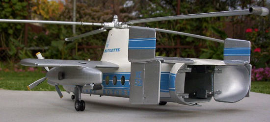
One of the cool parts of this kit are all the movable parts. The forward landing gear rotates back up, but can't be locked down. The main gear also rotates into its bay, with the ability to be locked down using a simple but effective mechanism. The propellers and rotor rotate and the rear elevators can move up and down. The most complex moving part are the rear doors, with hinges that pull out to allow the doors to be rotated 90 degrees. Most modellers glue the rear doors in, but as you can probably tell, I like moving parts on models, so I wanted to make my doors operable. Test fitting showed the doors would have a gap around all the edges, so I glued plastic card along the edges. After drying, the card was cut away and sanded down. Some of the edges were very thin, so I added some thin plastic card along the inside, to give the doors a little more strength. Inside of the doors was pretty rough, which required a bit of sanding to get smooth.
The cabin door can be positioned open or closed. I like my models to appear in the ready to take-off position, so this was glued in closed.
| COLORS & MARKINGS |
Due to the large sink marks, undercoat was sprayed several times until I got a smooth finish. The upper half was sprayed gloss white. I had used car polish in some areas which I not properly removed, causing the paint to go on non-uniformly. Also, the sink marks were still showing, so more sanding and painting. The white area was then masked. I had previously hand painted the spinners Humbrol 14 French Blue. This looked good, but was much too dark compared to the light blue decals. So, I remasked the spinners to spray them with a lighter blue, along with the canopy framing. I tried mixing up a lighter blue to match the decals, but whatever I tried I could not get a match. I eventually gave up and just used some random mixture!
The spinners and canopy areas were then masked up for my first ever metal
finish attempt with an airbrush. I sprayed one coat of Klear (or Future) which I
had imported from England. I should have given more coats, as the finish along
the sides was pretty rough due to the many sprays of undercoat. I used Humbrol
27002 Polished Aluminium straight from the tin. This went on very well and I was
very pleased with the result. You are supposed to polish this half an hour after
spraying, but I always forgot to do
 this! There were some bits of dust and other
defects I noticed, so these were sanded smooth. To help smooth out the sides, I
sprayed Humbrol 35 Gloss Varnish followed by a coat of Klear. Another spray of
metalcote and then another spray of Klear. The paint was starting to get a bit
thick, especially along the top of the wings, but it still looked OK.
this! There were some bits of dust and other
defects I noticed, so these were sanded smooth. To help smooth out the sides, I
sprayed Humbrol 35 Gloss Varnish followed by a coat of Klear. Another spray of
metalcote and then another spray of Klear. The paint was starting to get a bit
thick, especially along the top of the wings, but it still looked OK.
After removing all the masking tape except that over the windows, the decals were applied. The only real problem was on the port decals, which broke in some areas. This resulted in a patch of my non-matching light blue being applied in one area. Otherwise, the decals went on very well, with the carrier film invisible against the metal finish. The rear door decals needed a couple of applications of decal setting solution before they eventually settled. As the doors had not yet been glued on, there was some misalignment at the back of the doors.
A final coat of Klear was then applied. With one coat, Klear dries to a semi-gloss finish, which I think looks better than the enamel clear satin I had used previously used. The last of the masking was then removed. I had to use a knife to cut away some of the paint on the canopy, as it had gotten quite thick. Some of the framing lifted away. This was fixed by remasking and hand painting those areas. The new framing looks great, allowing a much clearer view into the cockpit.
The wheel doors were then glued on. This was followed by the small antennas I had made from plastic card that were superglued under the fuselage. Photographs of this area are not very clear, but I found an excellent Rotodyne short film made by Fairey that has a good shot of under the fuselage. The rear antenna broke off quite a few times, each time taking away a layer of Klear or paint!
After the engine exhausts (painted steel) and wheel doors had been glued on, I noticed that the paint on the ends of the wings was wearing away due to all my handling. The fuselage was masked up again and another spray of metalcote was applied, followed by another spray of Klear. Fortunately, this worked OK. I then made covers for the ends of the wings from paper, to avoid this problem in future. I also used Aeroclub rigging thread for the first time for the antenna wire under the fuselage. Drop of superglue at one end, dip thread in accelerator and stick to superglue. Stretch thread and repeat at other end. It took me a couple of goes, but I am well pleased with the result.
| FINAL CONSTRUCTION |
 The rear doors were then glued on. There is a small gap at the top of the
doors, most likely from over sanding the fuselage in this area. They worked
really well. The front probes were then glued in place. The bottom probe is just
a short piece of copper wire. The top probe was made from a needle, a small
piece of plastic card and a very short piece of copper wire. The probe is bent
at the point where it it enters the canopy. I had to heat the needle in order to
get it to bend, otherwise it would break. The probe was glued with clear drying
cement at the canopy, and superglued at the back of the probe from the front
doorwell. The probe is pointing slightly downwards, as seen in my reference
photos.
The rear doors were then glued on. There is a small gap at the top of the
doors, most likely from over sanding the fuselage in this area. They worked
really well. The front probes were then glued in place. The bottom probe is just
a short piece of copper wire. The top probe was made from a needle, a small
piece of plastic card and a very short piece of copper wire. The probe is bent
at the point where it it enters the canopy. I had to heat the needle in order to
get it to bend, otherwise it would break. The probe was glued with clear drying
cement at the canopy, and superglued at the back of the probe from the front
doorwell. The probe is pointing slightly downwards, as seen in my reference
photos.
The tips of rotor were painted steel, with some black detail painting to the rotor spinner. Finally the rotor was placed on its spindle and the spinner glued on. There was an airpocket in the top, so as I was pushing it down, the front gear collapsed and its door broke off! This was easily fixed though.
| CONCLUSIONS |
Despite the moulds being 37 years old when the kit was reissued, an excellent model can be made from the Airfix kit. However, I found that it needs a lot work. It tool me eleven months of weekends (mostly waiting for paint or putty to dry) to complete this. This was also my first metal finish and I can highly recommend the Humbrol metalcote paint that I used. I found it very easy to use, obtaining a realistic finish. If Airfix ever reissue this, I hope they clean up the moulds and also make sure the decals are the correct shade of blue. Getting rid of the alignment pins would also go a long way to removing the sink marks as well.
| REFERENCES |
B. H. Charnov, "The Fairey Rotodyne: An idea whose time has come - again?", Autogiro to Gyroplane: The Amazing Survival of an Aviation Technology, Praeger Publishers, July 2003.
Fairey Film Unit, Rotodyne, 84MB MPEG file. Excellent footage of Rotodyne taking off, in flight and landing, all to a hip background music track.
July 2006
Copyright ModelingMadness.com. All rights reserved. If you would like your product reviewed fairly and fairly quickly, please
contact
the editor or see other details in the
Note to
Contributors.