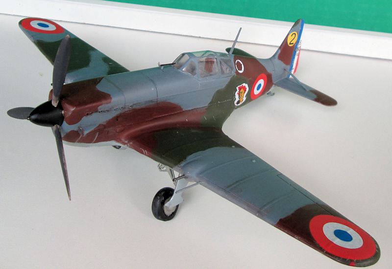
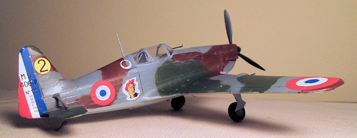
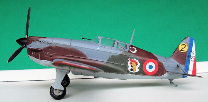
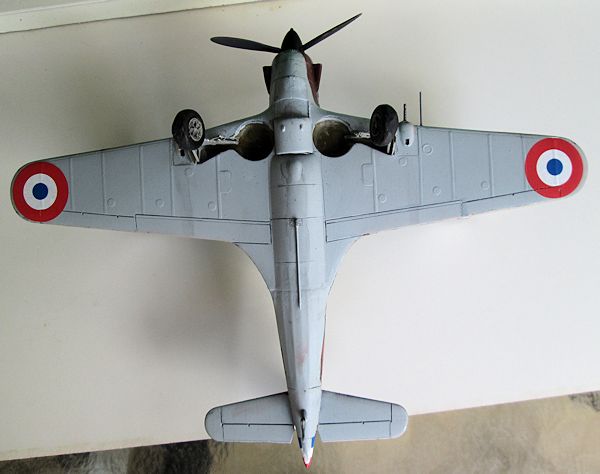
AZ Models 1/48 M.S. 406C.1 'in Africa'
| KIT #: | AZ 4807 |
| PRICE: | $45.00 |
| DECALS: | Three options |
| REVIEWER: | David Cummings |
| NOTES: |
Short run kit with resin and photo etch. Print Scale decals used. |
| HISTORY |
In response to a 1934 French
Air Force requirement for a modern fighter, Morane-Saulnier proposed the MS-405.
Re-designated 406 following several changes to the prototype, the MS-406 was a
contemporary of the Hurricane, Bf-109, and P-36. French labor problems and
nationalization of industry had its effect on the aircraft industry and problems
with engine deliveries delayed development and production. With war clouds on
the horizon the French Air Force desperately placed orders for foreign made
aircraft to make
 p for the slow production of French designs. Still, the MS-406
was the most numerous fighter type in French service when the Nazi’s invaded May
1940. However only 535 had been delivered by this time though production did
ramp up. Delays also hampered development of the type against its
contemporaries. The Hurricane was already being overshadowed by the newer
technology Spitfire and the P-36 was being replaced by its Allison powered
offspring the P-40. The MS-406 performed well against its anticipated
antagonist, the Bf-109B. Unfortunately it now faced the Bf-109E which had
developed into a much higher performing aircraft. As a result 387 MS-406s were
destroyed in the 1940 conflict (150 in air combat) though Morane pilots gave a
good accounting of themselves in claiming some 190 enemy aircraft before the
French surrender.
p for the slow production of French designs. Still, the MS-406
was the most numerous fighter type in French service when the Nazi’s invaded May
1940. However only 535 had been delivered by this time though production did
ramp up. Delays also hampered development of the type against its
contemporaries. The Hurricane was already being overshadowed by the newer
technology Spitfire and the P-36 was being replaced by its Allison powered
offspring the P-40. The MS-406 performed well against its anticipated
antagonist, the Bf-109B. Unfortunately it now faced the Bf-109E which had
developed into a much higher performing aircraft. As a result 387 MS-406s were
destroyed in the 1940 conflict (150 in air combat) though Morane pilots gave a
good accounting of themselves in claiming some 190 enemy aircraft before the
French surrender.
Maurice Arnoux was a WWI five victory ace. He was an active pilot in the interwar years and a winning air racer, notably with the Caudron 460. Recalled to active service as war threatened, Commandant Arnoux was squadron leader of 6 Escadrille, Group de’Chase III/7, Armee de L’Air. He was shot down and killed 6 June 40.
| THE KIT |
The Kit
– This is one of those Czech, limited run, mixed media kits. The major airframe
pieces are on two sprues of tan plastic, well molded with very good engraved
detail. A separately bagged resin sprue comprises the cockpit with good sidewall
detail. Nice resin wheels are flattened and bulged at the bottom, however this
doesn’t really match the angle of the 406’s wheel camber. Small detail pieces
are on a fret of photo-etch metal including seat harness, pre-painted instrument
panel parts, even those tiny leather
 straps that hold your feet on the rudder
pedals. A section of metal tubing is to be cut to make the wing guns. Two vac-form
canopies are provided on one acetate sheet. A nice addition is a die-cut
adhesive sheet for masking the canopy. Instructions are in English on a folded
sheet dividing it into four pages. The construction steps are generally well
drawn but a bit vague in places and downright misleading in others (details to
follow). Decals appear well printed with three Africa based options. Painting
and decal guides are the color profiles on the back of the end opening box.
Paint references are for Gunze-Sangyo and Agama.
straps that hold your feet on the rudder
pedals. A section of metal tubing is to be cut to make the wing guns. Two vac-form
canopies are provided on one acetate sheet. A nice addition is a die-cut
adhesive sheet for masking the canopy. Instructions are in English on a folded
sheet dividing it into four pages. The construction steps are generally well
drawn but a bit vague in places and downright misleading in others (details to
follow). Decals appear well printed with three Africa based options. Painting
and decal guides are the color profiles on the back of the end opening box.
Paint references are for Gunze-Sangyo and Agama.
If you are not a veteran of these kinds of kits I will tell you how I approached this build. I know that everything is provided to make an accurate detailed replica. But there will be more challenges along the way than you normally get building one of the mainstream brands. Accept that so when you do hit a bump in the road it doesn’t upset you. The kit will build into a great model, but there will be things that make you wonder how at times. Test fit, test fit, test fit. I also highly recommend you gather some good reference pictures/drawings beforehand. I have attempted to identify all the pitfalls encountered in building this kit and hopefully guide you through them.
| CONSTRUCTION |
The
cockpit is constructed as a completed tub to be trapped between the fuselage
halves. If you have not worked with resin before notice how this medium allows
for sharper detail relief than can be molded in plastic. Resin is softer than
plastic and cuts more easily, but is also more brittle and easily broken.
 One
problem is the parts have to be cut from molding sprues or blocks. A razor saw
is handy for this, you can cut it off with a hobby knife but the pressure you
have to exert makes it more likely to break something. There is some molding
flash to be cleaned up. Small delicate pieces have to be detached and cleaned up
with care and you will likely still wind up breaking something. Use a cyano/superglue
to cement resin parts.
One
problem is the parts have to be cut from molding sprues or blocks. A razor saw
is handy for this, you can cut it off with a hobby knife but the pressure you
have to exert makes it more likely to break something. There is some molding
flash to be cleaned up. Small delicate pieces have to be detached and cleaned up
with care and you will likely still wind up breaking something. Use a cyano/superglue
to cement resin parts.
The instrument panel is comprised of 9 photo-etch pieces glued to the plastic panel. You have pieces with pre-painted instrument dials, you glue the pieces with the holes over these so the dials line up in the holes. I cemented these pieces together with white glue which dries clear and looks kind of like the glass covering the dials. This produces a very realistic instrument panel that puts instrument decals to shame. Side panels, seat and rear deck were painted light grey per the instructions. I used a neutral grey to accentuate the framing detail for some contrast. Radio panel, levers, and other details were painted appropriately. The photo-etch seat harness was painted, molded to shape into the seat and glued in place. Photo-etch is easily cut from the fret with a sharp pointed hobby knife blade and cyano is again the glue of choice. I like the thicker kind that helps hold parts in place as it dries. As for those tiny stirrup straps for the rudder pedals, how are you at brain surgery? Probably about the same, I passed.
If you
follow each instruction step closely, then when you get to Step 6 you will find
you have entered the Twilight Zone where nothing makes sense anymore. It shows
attaching the forward bulkhead and instrument panel by gluing the floor into a
molded slot in the bulkhead. However this aligns the instrument panel too low.
The next step showing a nearly completed cockpit tub depicts the floor aligned
with the bottom edge of this bulkhead. If on the other hand you are smart
(unlike me), and carefully study all of the construction steps before you start,
then you will be able to reach the conclusion beforehand that them Czechs must
be smoking some good stuff. It appears they noticed there was a problem but
couldn’t figure out what do about it. So in exasperation they added a separate
drawing in Step 6 instructing you to saw 3.5mm from the floorboard which was
already glued in place in a previous step. Of course this would do absolutely
nothing to solve the problem anyway. So I put it together the way that made the
most sense to me. After admiring my beautifully detailed cockpit, I tore it all
apart again as there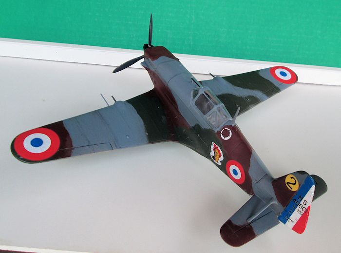 was no way in heck this was going to fit into the fuselage.
Way too big and the instrument panel still did not line up correctly. But again,
all this was expected so I was not terribly upset. So, how to proceed? This is
how I did it, not saying it’s the best way, but it worked. I glued the fuselage
halves together first. Be careful aligning the halves as there are no alignment
pins but fit is good requiring only the normal seam cleanup.
was no way in heck this was going to fit into the fuselage.
Way too big and the instrument panel still did not line up correctly. But again,
all this was expected so I was not terribly upset. So, how to proceed? This is
how I did it, not saying it’s the best way, but it worked. I glued the fuselage
halves together first. Be careful aligning the halves as there are no alignment
pins but fit is good requiring only the normal seam cleanup.
I installed the cockpit one section at a time into the assembled fuselage cutting and filing as needed. First I glued the seat and aft deck to the rear bulkhead. When dry I cemented this into position in the fuselage. With a little trimming to fit it went in OK. Then I glued the forward bulkhead and instrument panel in place, fit like a glove. That left the side panels as the culprit. I cut about a quarter inch from the rear of each and thinned them with course emory boards until I could see daylight through them. With a little more trimming to fit they slid into place. Cap it off with the floorboard and it’s done and looks good. The resin roll-over bars have to be carefully cut away from some molding flash. There is also a set of plastic ones that are easier to handle and look nearly as good. Test fitting showed the legs of both have to be shortened a bit to fit properly on the rear decking. The instructions for this assembly are more confusing than helpful. Check references.
Next was the wings. There are some strange long pins sticking out of the interior sides. They have to be cut off for the wings to mate. I dry fit the gear well inserts and as I suspected they interfered with the fit of the wing halves. I filed down the inserts test fitting as I went. With that the wings assembled quite well requiring no filler. The wings were then joined to the fuselage and fit was good. I took issue with that pesky belly seam where the rear edge of the wing assembly meets the underside of the fuselage. It cuts across a fabric over frame area making it difficult to fill and sand the seam without erasing frame detail. Some Hurricane kits are notorious for this and I cursed the insensitivity of the kit designers. Then I checked my Richard Caruana drawn scale plans. Hey! There is a seam across the belly exactly where the kit’s is. It’s supposed to be there.
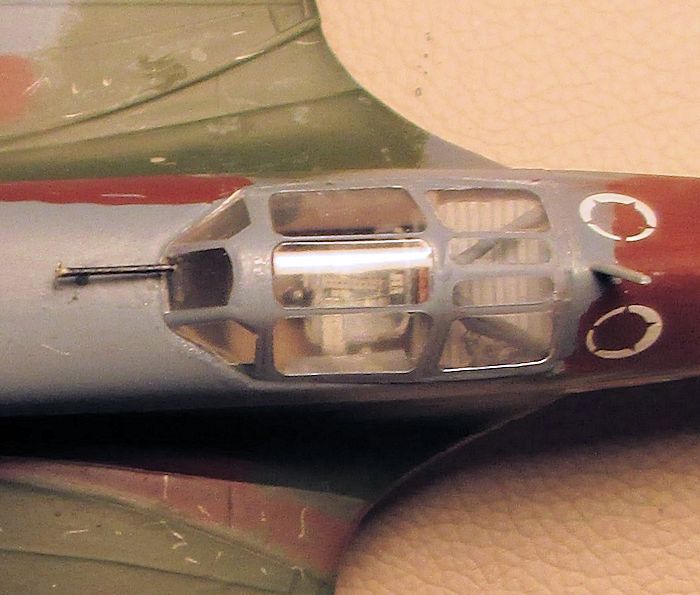
The resin air-scoops each side of the nose and their PE screens went on with no issue. The radiator PE screens are a bit undersized leaving small gaps to be filled along the edges. I painted the interior black and glued the radiator in place. The horizontal stabilizers and their braces were next and glued with Testor’s liquid cement. There are no slotted tabs but there is a molded outline to guide placement. Then I noticed there was still more stuff on the PE fret. I knew about the ring sight stuff but there are also a bunch of tiny little ovals on the fret which the instructions make no mention of. What are they? Someone had gone to some trouble to produce the tiny precise looking little things, but for what? Looking the model over I decided the exhaust manifold areas look pretty bare being just molded square blobs, I elected to use the little ovals as exhaust ports and glued them in place six on each side. Is this what they are for? I don’t know, this only used up half of them. But I like the way it looks.
 At this
point I prepared the vac-form canopy. These are very nice canopies but again, if
you are new to multi-media kits and have not worked with vac-form prepare to be
challenged. The delineation between canopy and the backing sheet is not as
clearly defined as most I have worked with. Be careful cutting these from the
sheet because one overly aggressive cut can start a crack that will travel up
into the canopy (ask me how I know). I separated the canopies with small sharp
scissors. I then began cutting one out using a surgical blade (a new single edge
razor blade will work fine). You work carefully by repeatedly scoring the
plastic along the canopy edges until it finally comes apart from the sheet.
Don’t try and cut them out with one whack and don’t try and cut it too close.
Finish up by dry fitting and sanding the edges until you are satisfied with the
fit. This is an admittedly tedious process, fit and sand, fit and sand but
remember the old adage “you can always take more off but you can’t put it back
on again.” At this point you have to decide open or closed canopy. If you want
yours open hack into the center sliding portion of one canopy to produce good
front and rear sections, then hack the other canopy at the opposite ends to
produce a good sliding center section. That is if you are not one of those
aforementioned brain surgeons that can perfectly cut three good sections from
one canopy. I elected canopy closed. Next was masking with the provided pre-cut
masks which are marvelous. Lift them off the backing with the tip of your hobby
knife. They can be adjusted slightly with a tooth pick then press them down to
seal them when in place. When masked I attached the canopy with a small amount
of thick superglue. Once attached any gaps can be filled with clear parts cement
(expensive white glue) applied with a toothpick (a most valuable tool). Next I
attach the tail skid. I painted light gray primer over all glue seams to
identify areas requiring more work. No filler was needed except some Mr.
Surfacer here and there. With the seams sanded out I re-scribed some lost panel
lines and she is ready to paint.
At this
point I prepared the vac-form canopy. These are very nice canopies but again, if
you are new to multi-media kits and have not worked with vac-form prepare to be
challenged. The delineation between canopy and the backing sheet is not as
clearly defined as most I have worked with. Be careful cutting these from the
sheet because one overly aggressive cut can start a crack that will travel up
into the canopy (ask me how I know). I separated the canopies with small sharp
scissors. I then began cutting one out using a surgical blade (a new single edge
razor blade will work fine). You work carefully by repeatedly scoring the
plastic along the canopy edges until it finally comes apart from the sheet.
Don’t try and cut them out with one whack and don’t try and cut it too close.
Finish up by dry fitting and sanding the edges until you are satisfied with the
fit. This is an admittedly tedious process, fit and sand, fit and sand but
remember the old adage “you can always take more off but you can’t put it back
on again.” At this point you have to decide open or closed canopy. If you want
yours open hack into the center sliding portion of one canopy to produce good
front and rear sections, then hack the other canopy at the opposite ends to
produce a good sliding center section. That is if you are not one of those
aforementioned brain surgeons that can perfectly cut three good sections from
one canopy. I elected canopy closed. Next was masking with the provided pre-cut
masks which are marvelous. Lift them off the backing with the tip of your hobby
knife. They can be adjusted slightly with a tooth pick then press them down to
seal them when in place. When masked I attached the canopy with a small amount
of thick superglue. Once attached any gaps can be filled with clear parts cement
(expensive white glue) applied with a toothpick (a most valuable tool). Next I
attach the tail skid. I painted light gray primer over all glue seams to
identify areas requiring more work. No filler was needed except some Mr.
Surfacer here and there. With the seams sanded out I re-scribed some lost panel
lines and she is ready to paint.
| COLORS & MARKINGS |
 I
bought this Africa boxing of the kit because of a good deal. But I really wanted
a France 1940 plane for my collection. For this I had on hand the Print Scale
decal sheet and selected Arnoux’s Morane. There is a photo of Arnoux and
the squadron insignia “the Furies” on his MS-406 while based at Vitry, May 1940.
I
bought this Africa boxing of the kit because of a good deal. But I really wanted
a France 1940 plane for my collection. For this I had on hand the Print Scale
decal sheet and selected Arnoux’s Morane. There is a photo of Arnoux and
the squadron insignia “the Furies” on his MS-406 while based at Vitry, May 1940.
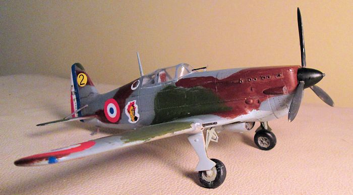
First I pre-shaded most panel lines black. I airbrushed Dave Cummings equivalent French colors. Testor’s Acryl RLM 76 was sprayed on the undersides. When dry the demarcation line was masked with Tamiya tape. I mixed some Testor’s US Navy Blue-Gray into Tamiya Neutral Gray to blue it up some and sprayed the uppers. When that dried I used a soft lead pencil to lightly draw my camo patterns, marking with Xs the areas to be painted brown and the green areas with Os. MS-406 camo patterns are puzzling in that, except for colors, there is no apparent “standardized” pattern as there is with British subjects. All I had were several different port side profiles, none of which agreed with each other. I selected the most likely and just guesstimated the rest of the scheme. Using Testor’s small bottle enamel Brown I filled in the brown areas freehand. Make sure the pencil markings are painted out completely. Overspray was wiped clean with a T-shirt rag moistened with thinner which will not attack the underlying acrylic and gives a semi-hard edged pattern without masking. When dry I coated with Testor’s Gloss Coat lacquer (acrylics don’t like to stick to enamels). I filled the green areas with AV Russian Green acrylic. Again overspray was wiped clean with Testor’s acrylic thinner which doesn’t bother the lacquer (soapy water will work almost as well). I dirtied it up a little with some black acrylic wash, some pastel exhaust stains, dings from a silver pencil, etc. The demarcation line masking tape was removed and thankfully no paint lifted with it. Another coat of clear gloss and ready for decaling.
 The
Print Scale decals are well printed, opaque, and easy to handle and maneuver
into position. The decals only need a couple seconds in water and if left in too
long will float off its backing and you will have to fish for it. They settle
down well over most detail which is good because mine were nearly impervious to
decal solvents. I used repeated applications of Micro-Sol to melt a rudder
stripe bubble over the rudder trim tab actuator cable and it still wound up
being just OK. I sealed the decals with another coat of gloss and when dried
finished with Testor’s Dull Coat. When that dried I removed the canopy masking.
This project was done over several weeks a little here and a little there. So
that and the layers of paint had me concerned how easily the masking would peel
off. Good stuff, it released easily and there was no bleed under. Landing gear
struts were cleaned up and painted light gray and inside gear doors and wheel
wells painted olive drab per instructions.
The
Print Scale decals are well printed, opaque, and easy to handle and maneuver
into position. The decals only need a couple seconds in water and if left in too
long will float off its backing and you will have to fish for it. They settle
down well over most detail which is good because mine were nearly impervious to
decal solvents. I used repeated applications of Micro-Sol to melt a rudder
stripe bubble over the rudder trim tab actuator cable and it still wound up
being just OK. I sealed the decals with another coat of gloss and when dried
finished with Testor’s Dull Coat. When that dried I removed the canopy masking.
This project was done over several weeks a little here and a little there. So
that and the layers of paint had me concerned how easily the masking would peel
off. Good stuff, it released easily and there was no bleed under. Landing gear
struts were cleaned up and painted light gray and inside gear doors and wheel
wells painted olive drab per instructions.
| FINAL CONSTRUCTION |
Assembling the landing gear is pretty straight forward. The instructions here are OK if a little vague. There are no locating holes, alignment pins, or anything else on the parts that indicate where they fit together. Test fit to know how it all goes together. The axles to wheels attachment points need some attention here to mate properly. I slopped on plenty of Testor’s liquid cement and glued the legs in place bracing them against the wheel well wall. This allows a pretty sturdy assembly. Make sure they are square with one another. I scraped paint away from glue contact points and the retraction parts were glued to the struts. Then the gear doors were glued in place. After allowing the assembly to dry thoroughly I attached the wheels with cyano making sure the tire flat spots are on the bottom. The gear legs have that quirky Morane wheel camber built in and looks right.
 Instead of the supplied tubing I
selected some appropriate looking plastic .30 cal barrels from the spares box. I
drilled some locating holes in the MG housing with a pin vise and also a
locating hole for the pitot. For some reason they don’t include a pitot tube but
the instructions have a drawing with the dimensions to make your own (I used the
uncut wing gun tube, a little on the short side, I know). There are two options
for the ring and bead sight mount. One is a resin mount with individual PE ring
and bead post (which approaches the microscopic realm) parts. The other is a
single PE part for which you twist the ring sight ninety degrees into proper
alignment. Both are full of frustrations for one thinking he is nearly finished
with the model. I broke the resin piece into a zillion pieces cutting it from
the sprue. The PE part is going to give you two or three chances to stick it in
place before it bends into a wiggly worm shape. I failed miserably with both
options and had to scratch build mine. I drilled a hole in the fuselage and
glued in a piece of plastic rod for the forward bracket which made a solid
foundation to attach a mount. And, I’m still smiling, see…. The dorsal and
unique ventral antennae are included and these were painted and glued in place.
Instead of the supplied tubing I
selected some appropriate looking plastic .30 cal barrels from the spares box. I
drilled some locating holes in the MG housing with a pin vise and also a
locating hole for the pitot. For some reason they don’t include a pitot tube but
the instructions have a drawing with the dimensions to make your own (I used the
uncut wing gun tube, a little on the short side, I know). There are two options
for the ring and bead sight mount. One is a resin mount with individual PE ring
and bead post (which approaches the microscopic realm) parts. The other is a
single PE part for which you twist the ring sight ninety degrees into proper
alignment. Both are full of frustrations for one thinking he is nearly finished
with the model. I broke the resin piece into a zillion pieces cutting it from
the sprue. The PE part is going to give you two or three chances to stick it in
place before it bends into a wiggly worm shape. I failed miserably with both
options and had to scratch build mine. I drilled a hole in the fuselage and
glued in a piece of plastic rod for the forward bracket which made a solid
foundation to attach a mount. And, I’m still smiling, see…. The dorsal and
unique ventral antennae are included and these were painted and glued in place.
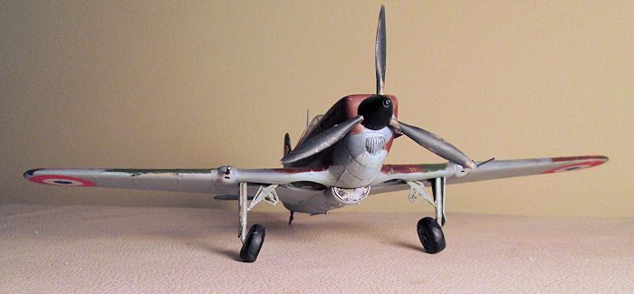
The prop is individual blades cemented to the spinner. The attachment holes have to be drilled out in the spinner. I matched a bit of the proper diameter. Be sure to drill straight to keep your blades symmetrical (straight in this case is parallel with the axis of the spinner, not its sloped sides). Careful cutting the blades from the sprue. What may appear as sprue is actually the shaft that inserts into the spinner holes. A spinner backing plate has a shaft to cement the assembly to the nose (hole in nose has to be enlarged a little). No turning prop here. And with that, FINIS!
| CONCLUSIONS |
Some of the stuff in this article may be a bit redundant to you experienced modelers. My intent is to encourage modelers with less experience who may be contemplating purchasing one of these kits or who has acquired one and upon opening the box may have found it too intimidating a project. But hey, if I can do it anyone can. I’m as ham fisted a modeler as you are likely to encounter. So jump in there. It ain’t easy, but I have tried to lay it all out for you how to get it done. The result is an accurate, detailed replica of the type that makes that old Hobbycraft Morane look downright crude in comparison.
| REFERENCES |
Article and Richard Caruana scale drawings in Scale Modeler International, Volume 3, Issue 10; Modeling Madness Kit Reviews; Wikipedia; www.wings palette.com.
David Cummings
August 2015 If you would like your product reviewed fairly and fairly quickly, please contact the editor or see other details in the
Note to
Contributors.