|
KIT # |
1206 |
|
PRICE: |
£16.25 |
|
DECALS: |
1702 Squadron,
FAA |
|
REVIEW : |
|
|
NOTES: |
|
|
HISTORY |
The Supermarine company may be best remembered for its graceful Spitfire, but the company designed a series of utilitarian flying boats and amphibians alongside the Schneider trophy racers that led to the Spitfire. Throughout the Second World War, the Supermarine Walrus served from land and sea, performing air/sea rescue (ASR), gunnery spotting and other duties with the Royal Navy. The Sea Otter resembles a modernised Walrus, with a conventional, tractor propeller installation, driven by a Bristol Mercury XXX radial engine. The Sea Otter entered Fleet Air Arm (FAA) service in 1944. It continued in service for some years, outlasting the Swordfish and Albacore to claim the title of the last biplane in squadron service with the FAA.
After the end of the war, British aircraft in India were turned over to the French Aeronavale. The Sea Otters were flown to Indochina, where they served with Escadrilles de Servitude 8S and 9S, replacing even more archaic Loire 130s. The Sea Otters served into the 1950s, despite the fact that the basic design was essentially obsolete before it ever flew.
|
THE KIT |
Aeroclub's Sea Otter is a mixed-media kit with vacuum-formed fuselage (hull) halves and canopy; injection-moulded wings, horizontal stabiliser, rudder, nacelle, outrigger floats and interior; and white metal engine, propeller, landing gear, wheels, struts and small interior details. Lengths of plastic rod, a strip of thin sheet, and some extruded airfoil section strut material round out the contents. This all comes packed in a tiny box with a line drawing of the aircraft on the lid.
The quality of the parts varies. The vacuformed parts look quite good, with light detail on the hull sides. The canopy is very clear, though the framing is indistinct, as is the actual edge of the part. The injection parts are moulded on very heavy, brittle sprues, and the attachment points and mating surfaces require a lot of clean up. The exterior parts have a distinct texture to them, and benefit from rubbing down with some wet and dry to smooth them out. Minimal panel detail is scribed into the parts- the scribing is uneven, and tends to disappear during clean-up of the parts. The interior parts show basic detail, acceptable considering the limited run moulding. The white metal parts are a bit disappointing, given that these are Aeroclub's speciality. Heavy flash is present on many of the cast parts, and pitting is evident in some prominent areas.
Decals are included for a Malta-based FAA machine. The markings are cleanly printed by Fantasy Printshop. For those interested in something a little different, both Model Art and Dutch Decals provide sheets with some alternative foreign schemes.
The weakest point of the kit is the instructions. They consist of a two single-sided A4 sheets, one with a written description of the construction process, and the second with a multi-view scale drawing, also illustrating the colour scheme and decal placement. The camouflage pattern is illustrated with hatching on the scale plan- this makes it very difficult to clearly identify details on the drawings. The plans themselves closely resemble those from Aviation News, and are weak on some specific details. In particular, rigging details must be inferred from the views and the boxtop drawing. The written instructions are not very helpful in areas such as assembling the interior components- the components here are not identified, and it is up to the modeller to sort out what's what and where it all goes (we are modellers, after all, though!)
|
CONSTRUCTION |
Construction started with clean-up of the white metal components. A lot of filing and polishing was necessary to get these into a useable state. The parts themselves lack crispness, but look the part once prepared and painted. The plastic parts were removed from the sprues with a razor saw, and rubbed down with fine grit wet and dry paper. The vacuum formed fuselage halves were removed from their backing sheet using the usual techniques. Assembly begins in the cockpit, which is kitted out with three bulkheads (one includes some raised instrument detail), sidewall panels, a floor, navigators table, two white metal seats, and a white metal control column. I added belts to the seats, then painted everything using Humbrol interior grey-green, with brown seat pads and a black instrument panel. The fit of the assembly is very vague, and I ended up with gaps between the bulkhead and the top of the fuselage and the canopy. This is a case of cut once, measure umpteen times. With the cockpit in place, the fuselage halves can be assembled. I added some bracing from scrap sprue around the cutout for the lower wing tab, to keep the fuselage relatively rigid in this critical area.
With the fuselage drying, I moved to the upper wing. This consists of upper and lower nacelle halves and left and right upper wings in injected plastic, with white metal cowl and intake scoops. I found the mating surfaces of the nacelle far from true, and even after sanding flat I still needed to fill large gaps at the rear with scrap plastic. Looking at the wings, the trailing edges are quite heavy, and benefit from scraping down. This reduces the scalloped effect of the moulded fabric, which is a little overdone in my opinion. Adding the wing halves to the nacelle required lots of cleanup of the mating surfaces, and plenty of filler.
Moving back to the lower fuselage, the lower wings were added, and again gaps were filled. The horizontal stabiliser fits into a cutout in the vertical tail, and a reasonable fit was achieved here. The rudder is a separate part, so I drilled holes in the vertical stabiliser to accept wire pins to allow mounting of the rudder after painting.
The outrigger floats are each split vertically, and have deep grooves in their upper surfaces to accept white metal struts. Filler was needed here to blend the struts into the floats. There seem to be small mounting pins moulded into the tops of the struts, but they are very poorly defined.
I then decided it was time to face the dreaded canopy. After carefully trimming the part from its backing, stopping frequently to check the fit against the kit, I ended up with something I was reasonably happy with. I added a small plastic shelf at the rear of the cockpit, under the solid part of the canopy, to provide a secure mounting point. After coating the canopy with Klear, I superglued it in place. Once set, I surveyed my handiwork, and decided I wasn't happy. The rear edge of the canopy was wider than the fuselage where they met, likely due to overzealous sanding of the vacuformed fuselage halves. Strangely, I decided the best way to fix this was to modify the canopy, so I carefully removed a tiny wedge of the clear plastic and bent the remainder back to fit the fuselage. The work was concealed in the solid portion of the canopy.
I suppose at this point a more experienced builder of multi-winged things would have a carefully mapped out plan of attack to handle the rigging and struts. Suffice it to say, I didn't. What I ended up doing was fitting the white metal engine struts to the upper wing/nacelle assembly, fixing the outriggers to the lower wing, drilling holes to attach the rigging later, and leaving all the remaining struts until after painting. The upper wing/nacelle and lower wing/fuselage were painted as separate subassemblies. This approach was decided upon after several less successful attempts.
I chose to leave off most of the easily-breakable bits until after painting, though I did add the grab rails to the fuselage, fore and aft. I used the plastic rod provided in the kit to make the mounts for the rails (note that the locations of the mounting points shown in the drawings do not match the small indentations in the kit- I went with the drawings, and filled the dents). I made the rails themselves from stretched sprue, carefully gluing the rail to each support in turn to give the correct curvature.
I also added a few details, in the shape of a landing light in the leading edge of the port lower wing, and two lamps in the trailing edge of the rudder. Other details that are shown on the drawings, and can be added to the kit include flap hinges, Yagi radar aerials and a pitot tube on the interplane struts, and radio aerials. I scratchbuilt these from scrap and sprue, and added them once painting, decal application and major assembly was complete.
|
PAINT & DECALS |
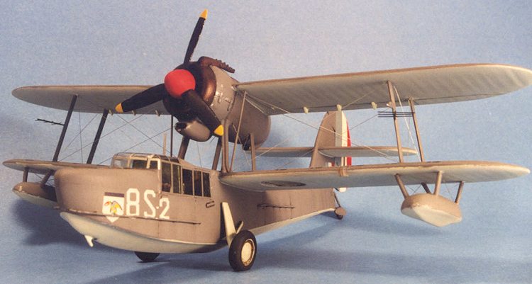
I had elected to finish my Sea Otter as one operated in French
Indochina in the late 40s/early 50s. An excellent set of markings for two such
aircraft is available from Model Art decals. These include a thoughtful
instruction sheet, with a very reasonable discussion of what colours these
aircraft may have been painted. I opted for dark sea grey over sky. All colours
used were from the Humbrol range. Prior to painting, I masked off all of the
transparency, to add the framing later from painted decal strips. The sky
undersurfaces were pre-shaded with flat black, while the dark grey was faded
using an overspray of a slightly lightened version of the base colour. While painting, I also spayed lengths of strut stock and rod in
the appropriate colours to install them later. The white metal prop, engine and
cowl were primed, filled, reprimed, refilled, and eventually sprayed in
appropriate colours, using a mixture of Bronze and dark brown for the exhaust
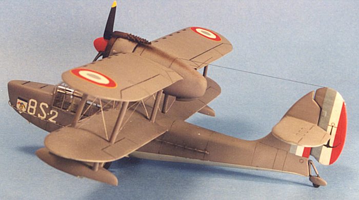
collector ring. The rudder was sprayed white as a basis for the tricolour
stripes to be applied later. All the bits were oversprayed with clear gloss, and once set, I
applied a wash of black and brown watercolours, highlighting the panel and hinge
detail, and trying to simulate some of the gunge that would accumulate on a
working amphibious aircraft. The watercolour wash was sealed with another coat
of clear gloss. I then moved to the markings. Model Art's latest decals are very
thin, and tend to stick where they are placed. They do hold up to handling,
however. Most of the multicolour markings are made up of several overlapping
images, so if they end up out of register, it's your fault! I encountered a
couple of problems with the decals- first, if placed as shown in the
instructions, the large numbers on the nose and the squadron badge interfere
with the grab rails. I ended up cutting slits in the decals, and touching up
later with paint. I found the lines delineating the walkway on the lower wing to
be too flimsy to work with, and gave up after they became hopelessly tangled.
The footprint markings on the upper and lower wings are provided as individual
markings. Without a full-scale diagram to show the placement of these, it's
difficult to ensure they end up evenly spaced. After leaving the decals for a few days, I sealed everything with
a coat of clear flat. Once this was fully dry, I could move on to the joyous
process of attaching the upper wing and rigging the model. I cut some jigs from
cardboard to hold the wings in position relative to one another, based on the
scale drawings provided. It seemed to me that the forward engine struts are
slightly too short, so I ended up with my wings a little too close together.
Each of the other struts was cut from the strut stock provided, trimmed to fit,
and superglued in place. I found the strut stock to have a noticeable grain or
texture, and each section required a thorough sanding to smooth it out. With the
struts in place, I began to add the rigging. I used monofilament sewing thread.
Each section was cut overlong, secured at one end in a shallow hole, then
trimmed to a little over the required length and glued into a hole at the
opposite end. Late the lines were tightened using a little smoke. In doing so, I
managed to break a lot of the rigging, and in future I'd recommend drilling
through holes at all the rigging locations, and pulling the lines taut while
gluing. It's then easy enough to clean up the mounting points. After what seemed like weeks, I had a (reasonably) fully-rigged
aircraft. I painted the rigging with very thin aluminum paint, and touched up
the attachment points. The undercarriage was added, and at this point I found
that my model had a pronounced lean to port! This is exacerbated by the very
narrow track undercarriage- any slight difference in the vertical position of
the wheels is magnified at the wingtips. I sanded a larger flat on one tyre, and
added a shim of thin plastic under the other, which helped even things out a
little. The tailwheel was mounted in line with the slightly deflected rudder,
which was pinned in place. The painted exhaust collector ring, engine, prop and
exhaust were added, along with some exhaust staining along the nacelle. Finally
I added the aerial wire from more monofilament (note that this should go to a
point on the rudder in line with the rudder hinge line), the Yagi aerials (made
from stretched sprue), and the pitot tube.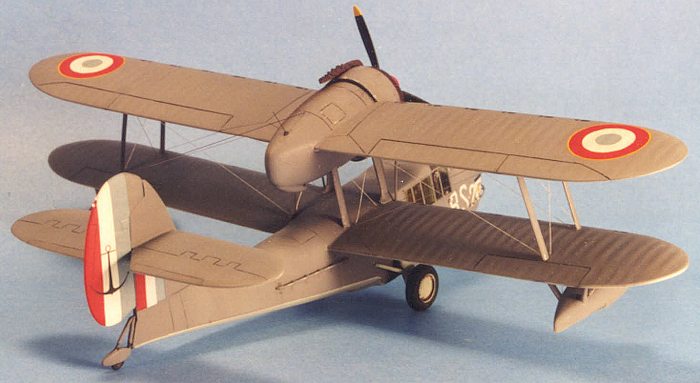
|
CONCLUSIONS |
Aeroclub's Sea Otter is not a kit for beginners. I spent about a
year on this project, including several periods of setting it aside in
frustration and reaching for something a little more straightforward. Compared
to the state of the art in limited run kits coming out of Eastern Europe, the
crude white metal parts and heavy mouldings look rather dated. That being said,
the kit is certainly buildable, and at present represents the only Sea Otter on
the market (I believe Azur have announced a forthcoming kit). It is certainly
within the capabilities of anyone whose cobbled together a limited run biplane
kit. The end result is a very unique model, one that draws attention wherever it
is displayed, and the Model Art decals make it even more unusual. I understand
that Aeroclub's more recent releases have been improving, and I'm sure many a
modeller eagerly awaits their forthcoming 1/48th English Electric
Canberra!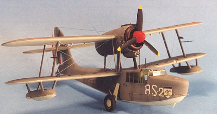
|
REFERENCES |
Aviation News Vol. 16, No. 2, 12-25 June, 1987
Copyright ModelingMadness.com. All rights reserved. No reproduction in any form without express permission from the editor.
If you would like your product reviewed fairly and quickly, please contact the editor or see other details in the Note to Contributors.
Back to Reviews Page 2025