Azur 1/72 Cierva C.30
|
KIT #: |
A015 |
|
PRICE: |
$13.00
|
|
DECALS: |
Four options |
|
REVIEWER: |
Peter Burstow |
|
NOTES: |
Short run kit |
 Designed
by
Juan de la Cierva
, the C.30 Autogyro was built by the Cierva Autogiro Company and first flew in
1933. It was license produced in relatively large numbers by Avro in the U.K.,
Lioré-et-Olivier in France and Focke-Wulf in Germany. They were variously
engined, Avro using the Armstrong Siddeley Genet Major 1A, LeO using Salmson
9Ne, and Focke-Wulf using the Siemens Sh14e.
Designed
by
Juan de la Cierva
, the C.30 Autogyro was built by the Cierva Autogiro Company and first flew in
1933. It was license produced in relatively large numbers by Avro in the U.K.,
Lioré-et-Olivier in France and Focke-Wulf in Germany. They were variously
engined, Avro using the Armstrong Siddeley Genet Major 1A, LeO using Salmson
9Ne, and Focke-Wulf using the Siemens Sh14e.
Of the 78 built by Avro, 12 were delivered to the RAF in 1934 and 1935,
called the Rota. Around 26 were exported to various civil and military users.
Many of the civil examples were impressed during WW2. Used for radar
calibration, the survivors were sold to civil owners after the war. About
eleven are displayed in museums around the world.
Around 35 parts in soft grey plastic make up this small kit. The parts have fine
engraved detail, and subdued fabric effect on the fuselage and flying surfaces.
The cockpit is sparsely furnished with seats, instrument panels and bulkheads.
There is flash and moulding joints on the parts, as well as prominent
 jector
towers, some of which will need removed.
jector
towers, some of which will need removed.
There are four resin parts, two for the seven cylinder engine and
exhaust, what may be a compass for the upper deck, and the rotor head. I doubt
that the rotor head part will be strong enough to support the three rotor
blades. There are four tiny vacformed windscreens supplied, two spares.
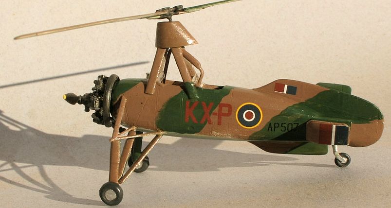
The decals have markings for four aircraft. An all green Czechoslovak Air
Force aircraft from 1936, a silver and grey French Navy example from 1938. A
camouflaged RAF aircraft from 1943, AP507 was one of the civil aircraft
impressed in 1940. An all silver Spanish Air Force aircraft is the fourth
option.
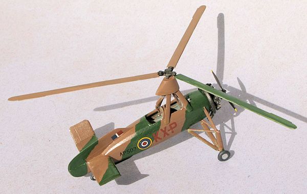
A nice touch is that the port tailplane is moulded with an inverse
aerofoil section, as in the real aircraft, to counteract torque.
For accuracy, the engine would need replaced for the French aircraft, as the
Salmson was a nine cylinder radial.
Added the floor, bulkheads, instrument panels and seats to a cockpit
half, and painted it all light grey, then touched up a few details and added lap
belts using blue tape. The cockpit is not really visible through the small
openings, and further concealed by the rotor pylon. I needed to trim the floor
and bulkheads slightly to close up the fuselage. Not much in the way of
sub-assemblies on this little kit. I
 attached
the three part tail planes and the rotor mast assembly. Removed the resin parts
from the pouring stubs and cleaned them up.
attached
the three part tail planes and the rotor mast assembly. Removed the resin parts
from the pouring stubs and cleaned them up.
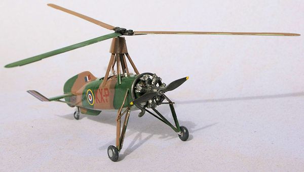
Joined the resin engine and exhaust, but did not attach it to the
fuselage. The resin parts were nicely moulded with fine detail. I drilled out
the ends of the exhaust collector. As the engine is exposed, I did a little
extra painting and dry brushing to bring out the details.
Needed a little filler and clean up on the fuselage joints.
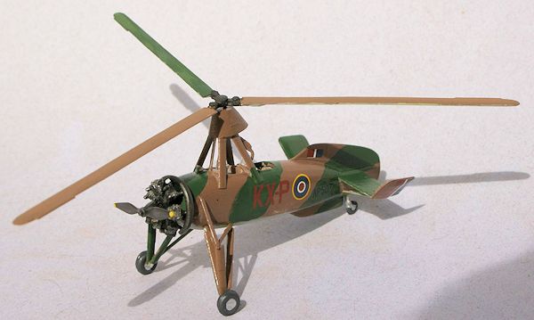
Assembled the complicated undercarriage, each leg having five parts,
making up two tripods. The whole thing being a maze of struts. Used the
instructions, box art and photographs I took of the preserved examples at the
RAF and the Science museums in London. Put the upper tripod together first, as
it was positively located to the fuselage, left it overnight to harden, then
added the lower tripod. Had to do some adjustment to leg lengths to make it
even.
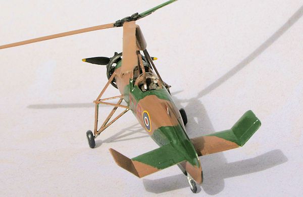
I picked the RAF version, light sea grey under-surfaces, with dark earth
and dark green top sides. Then added the decals using the profile supplied. The
uncowled radial engine needed a bit of special attention. I painted it and the
exhaust collector Mr Metal 'dark iron' then dry brushed highlights with Mr Metal
'chrome silver',
 Added the
painted resin engine and propeller and the wheels. I gave up on the vacformed
windshields, too small for me to deal with. I made new ones from a bit of
vacformed pill packaging.
Added the
painted resin engine and propeller and the wheels. I gave up on the vacformed
windshields, too small for me to deal with. I made new ones from a bit of
vacformed pill packaging.
I decided there was no way the resin rotor head was going to hold up the
rotor blades, so scratch built a new one using the resin part as a template. The
main structure was copper wire which I soldered into a caltrop. I added the
thinned resin rotor hub for decoration. Then drilled holes in the end of the
rotor blades to attach them. Bit of work but the result is strong enough, and I
was able to adjust the droop of the blades. Left the rotor unattached for easy
handling.
A nice little model of an interesting aircraft. There are not many
autogyro kits around. Went together very easily for a limited run kit, with the
resin engine a real highlight. Recommended.
http://en.wikipedia.org/wiki/Avro_Rota
http://en.wikipedia.org/wiki/Juan_de_la_Cierva
Peter
Burstow
September
2013
If you would like your product reviewed fairly and
fairly quickly, please
contact
the editor or see other details in the
Note to
Contributors.
Back to the Main Page
Back to the Review
Index Page