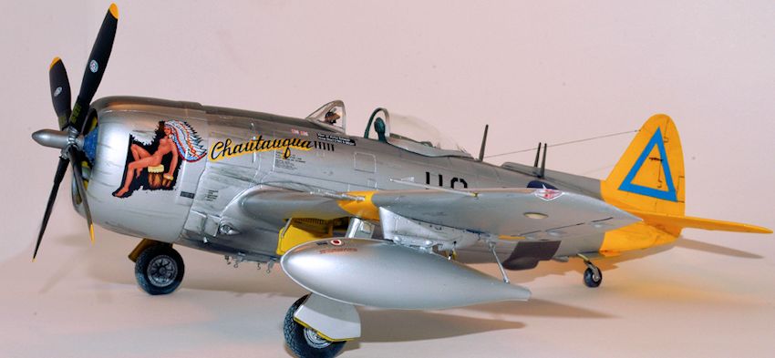
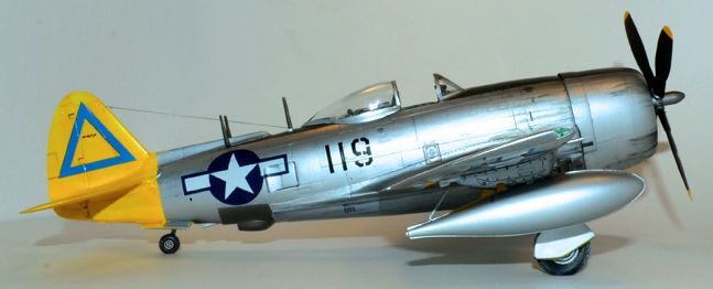
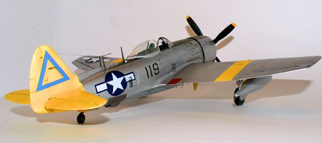
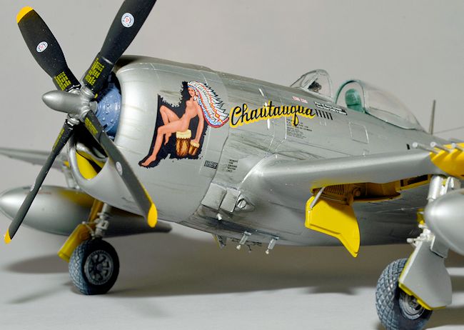
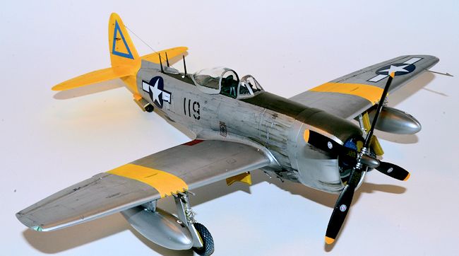
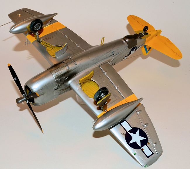
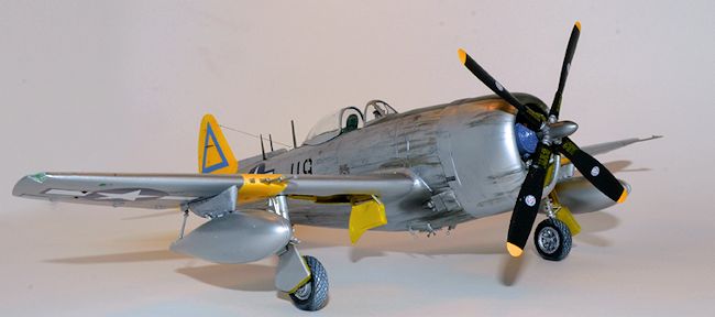
Revell 1/48 P-47N Thunderbolt
| KIT #: | 85-5314 |
| PRICE: | $22.95 SRP |
| DECALS: | Four options |
| REVIEWER: | Mike Still |
| NOTES: | Kits World sheet KSW148088 |
| HISTORY |
I leave
you to numerous books, websites and reviews here at Modeling Madness for the
big-picture history of the P-47. As for the N, Republic and Alexander Kartveli’s design team finally brought together all the refinements
developed through the bubbletop D-series and the P-47M - weapons including
rockets and
 bombs; Pratt & Whitney R-2800 with water injection; Curtiss
Electric paddle-blade prop - and a new, wider-span wing with blunt tips and
additional fuel tankage. The result was the second-fastest and
longest-ranged operational version of the P-47.
bombs; Pratt & Whitney R-2800 with water injection; Curtiss
Electric paddle-blade prop - and a new, wider-span wing with blunt tips and
additional fuel tankage. The result was the second-fastest and
longest-ranged operational version of the P-47.
P-47N’s
served almost exclusively in WW II as escort and strike aircraft in the
closing months of the Pacific war and stateside in the postwar and 1950s
period with Air National Guard and a few USAF units. Interestingly, the
postwar successor unit to the wartime 332nd Fighter Group also
flew the P/F-47N.
| THE KIT |
The kit
has 103 parts, including options for rockets, bombs, or a pair of 165-gallon
P-38/P-61-style drop tanks. Wheel wells consist of three wall pieces each,
with the main gear legs molded integrally with the rear walls.
If
you’ve built the classic Monogram Thunderbolt kits from the 60's, you’ll see
few similarities in the N’s parts layout. Although a new-tool kit when
issued, the parts quality and ease of construction suggest that Revell/Monogram’s
b-team handled the design and mastering.
The
finesse of areas like the aileron and flap ranges from poor to average, but
panel lines on the fuselage and empennage range from average to fair.
Engraving on the wing hardpoints is a bit on the deep side. Not Tamigawa,
but manageable. Generally, detail on the engine, cockpit and landing gear
parts is soft. So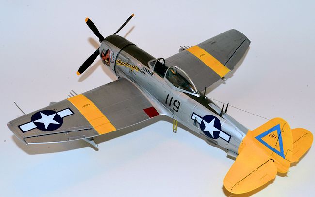 me cleanup with jewelers’ files will help sharpen up the
detail, but aftermarket gear would be better. Scale Aircraft Conversions
doesn’t have a P-47N gear on its list of available sets; given that they
would have to cast a gear wall too, it’s understandable.
me cleanup with jewelers’ files will help sharpen up the
detail, but aftermarket gear would be better. Scale Aircraft Conversions
doesn’t have a P-47N gear on its list of available sets; given that they
would have to cast a gear wall too, it’s understandable.
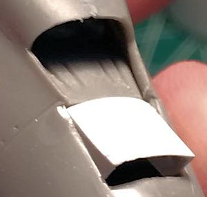
The
fuselage includes inserts for the undernose exhaust waste gates, side
supercharger ducts and the ventral turbo. The turbo and side vents fit well,
but the waste gates don’t fit in their recesses and will need some cutting
and filing. The two shutters on each gate either need a lot of thinning or
replacement with photo-etch or scratchbuilt pieces.
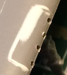
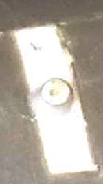
P-47Ns
had a mini-antenna farm on their spine, and ProModeler’s solution to that
was strange at best - a poor-fitting insert with the main mast and what
appears to be an insulator. Save yourself some trouble - trim off the
antenna and insulator, replace the insert with a chunk of plastic stock,
fair that into the fuselage and reattach the antenna and insulator later in
construction. (Dorsal insert pic)
The main
wheels have an overlapped-scale treatment for the diamond-pattern tread. Hub
detail is passable. You can use a scriber or razor saw to engrave the tread
lines but I chose to get a set of Ultracast replacements for the recessed
tread and sharper hub detail.
The
underwing stores lack the definition that you find in Tamiya or even the
older Monogram Thunderbolts’s weapons. The HVAR rockets are quite usable,
though, and the drop tanks need re-angling of the mounting tabs to hang
correctly. The 500-lb bombs can be replaced from one of several WW II US
kits.
 The kit
engine includes two banks of cylinders - two halves per bank - a prop shaft
and a fairly accurate crankcase for the N version’s R-2800. The engine does
not have the ignition harness, but detail otherwise is acceptable unless
you’re taking it to a contest.
The kit
engine includes two banks of cylinders - two halves per bank - a prop shaft
and a fairly accurate crankcase for the N version’s R-2800. The engine does
not have the ignition harness, but detail otherwise is acceptable unless
you’re taking it to a contest.
The
stock Curtiss paddle-blade prop compares fairly well to the propeller in the
Tamiya P-47M kit. An Ultracast propeller certainly would be sharper, but
it’s not a critical issue unless you’re competing with rivet-counters.
The
cowling still shows the step at the cowl ring that has been a tradition of
Monogram Thunderbolts since the 60's - easily fixed with masking tape and a
swipe of your favorite filler putty. A separate intake splitter installs
with little drama and causes no fit issues when attaching to the fuselage.
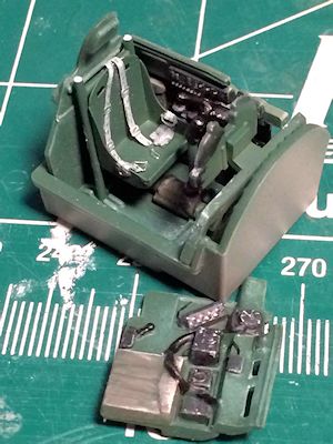
The
cockpit may be the biggest source of heartburn. Unlike the older Monogram
Thunderbolts’ instrument panel, stick and single-unit tub/seat/consoles, the
N cockpit consists of a floor, seat separate sidewalls, instrument panel,
separate rudder pedals, stick, throttle quadrant and flap handle. Detail is
soft, the instrument panel undersized, and fit of the sidewalls and bulkhead
less than positive. Lots of test fitting will be needed.
The
windscreen and canopy are slightly thick but have good clarity. A
well-detailed K-14 gyro gunsight, underwing landing light lens and two
undersized wingtip light covers round out the clear sprue.
| CONSTRUCTION |
I
started with the wing, because it had the most visible fit problems.
Test-fitting repeatedly, I installed the gear wells with my favorite cement,
methyl ethyl ketone - MEK - and clamped the parts in as best an alignment as
I could get. The inboard gear doors are integral to the inner well walls,
and I needed to keep them attached as a visual reference for well alignment.
Next time - if there is a next time - I’ll cut them off. Also, if there’s a
next time, I’ll engineer a way to install the gear legs later.
 . The kit also features a pair
of incredibly bad-fitting gun port
inserts with separate and anemic four-barrel insert units. I tossed
the gun barrels in the spares box, glued plastic strip inside the leading
edge fairings; the fairings do have the correct level alignment for the gun
openings, though. After gluing them securely in place, I packed the gaps and
sunken areas with Milliput epoxy putty. After that cured, I sanded the
fairings to shape and drilled excess putty out of the gun openings.
. The kit also features a pair
of incredibly bad-fitting gun port
inserts with separate and anemic four-barrel insert units. I tossed
the gun barrels in the spares box, glued plastic strip inside the leading
edge fairings; the fairings do have the correct level alignment for the gun
openings, though. After gluing them securely in place, I packed the gaps and
sunken areas with Milliput epoxy putty. After that cured, I sanded the
fairings to shape and drilled excess putty out of the gun openings.
 the fuselage
halves together to test fit the cockpit unit to ensure it fit high enough
for the cockpit rails on the sidewalls to sit exposed above the cockpit
opening. I then penciled along the lower tub edge inside both fuselage
halves, removed the tub and lightly scribed just above the pencil lines.
the fuselage
halves together to test fit the cockpit unit to ensure it fit high enough
for the cockpit rails on the sidewalls to sit exposed above the cockpit
opening. I then penciled along the lower tub edge inside both fuselage
halves, removed the tub and lightly scribed just above the pencil lines.
Testors Model Master Euro I green airbrushed on the fuselage sidewalls and cockpit unit made a fair match for Republic cockpit green. I scraped the paint away about 1/16th inch above and below the previously scribed lines inside the fuselage for a clear gluing surface.
Now for the fuselage itself; I cemented the side vent doors in place in the rear fuselage and test fitted the lower ventral turbo panel before cementing it with MEK and securing it with cyanoacrylate glue. The duct shutter after of the turbo vent also got cut away and replaced with one made from .010 plastic sheet.
 Remember
the screwy dorsal antenna insert? I cut a chunk of styrene bar stock,
cemented it in the insert slot and sanded it to shape when set. To provide a
more secure location for the wing later on, I cemented tabs from styrene
sheet just inside the front and rear wing openings in each fuselage half.
Finally, I cemented together the fuselage halves and let the assembly set.
Remember
the screwy dorsal antenna insert? I cut a chunk of styrene bar stock,
cemented it in the insert slot and sanded it to shape when set. To provide a
more secure location for the wing later on, I cemented tabs from styrene
sheet just inside the front and rear wing openings in each fuselage half.
Finally, I cemented together the fuselage halves and let the assembly set.
Rigging
the model works better with some planning at this stage. After beating my
head against a wall over several photos, I figured that the radio antenna
wire ran from its fin leading edge attachment to the insulator/isolator that
was on the fuselage antenna mount. I’d already drilled attachment points for
the three dorsal antenna posts, so I made a new isolator from carved and
sanded plastic rod. After attaching it to the fuselage, I drilled down
through it with a #78 drill bit into the fuselage interior. After all the
painting, decaling and final finishing, I figured I could rig, thread the
bitter end though the hole, grab it with tweezers through the tail wheel
mount opening and secure it. To save the suspense - it worked as planned.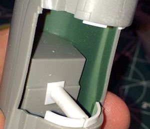
The kit provides zero positive location or retention for the cockpit. Solution? Make your own. I cemented the cockpit inside the fuselage and test fitted a length of plastic tube to wedge and cement between the cockpit floor and interior lower fuselage. For added insurance, I mixed up some epoxy putty and pressed it up and around the cockpit tub. (This is a particularly good idea as I had my cockpit come adrift when I built this kit after it was initially released. Ed)
After
attaching the wing with MEK and taping the dihedral in place, I found slight
mismatches along the lower fuselage/wing join that a few swipes of Tamiya
gray putty handled easily.
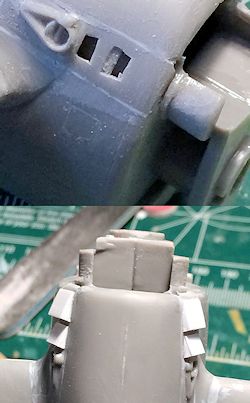 The oil
cooler vents and supercharger waste gates just forward and underneath the
wing root leading edge don’t fit, period. The cooler shutters also are lumpy
with thick edges. I cut away the shutter doors and spent some quality time
with a Dremel and small cutter bit to deepen the fuselage recesses. After
cementing them in place, I broke out the sanding sticks to blend them into
the fuselage before more swipes of Tamiya putty.
The oil
cooler vents and supercharger waste gates just forward and underneath the
wing root leading edge don’t fit, period. The cooler shutters also are lumpy
with thick edges. I cut away the shutter doors and spent some quality time
with a Dremel and small cutter bit to deepen the fuselage recesses. After
cementing them in place, I broke out the sanding sticks to blend them into
the fuselage before more swipes of Tamiya putty.
Using
flat and square jewelers’ files to refine the shutter openings, I then used
an old Eduard P-47N photoetch set (the same that provided the cockpit seat)
as a guide to cut new shutter doors from .010 styrene strip. After trimming
and light sanding, I got all four doors to fit. I could have used the Eduard
etch to refine the circular waste gates, but I felt than the kit
representation had a more three-dimensional look.
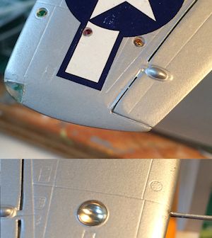
The horizontal stabilizers attached with little drama after cleaning up the mold seams on the leading and trailing edges. A swipe of Tamiya putty followed with a wipe of a nail polish remover-soaked q-tip took care of the gaps in that area. The vertical fin has shallow sink marks on both sides; I outlined the offending areas with masking tape, troweled a thin later of Tamiya putty across the marks, removed the tape and sanded the areas down after the putty cured.
Now,
while all this work had been progressing, I’d been taking several breaks to
research P-47N markings and equipment configurations. While working on the
fin, I noticed the kit has recessed points for the AN/APS-13 tail warning
radar introduced late in WW II for use on USAAF fighters. From the accounts
I’ve read over the years, pilots varied in their opinions on its usefulness.
Looking at various photos of Ie Shima-based Ns, I couldn’t find much
evidence to suggest its widespread use, but I decided this model was going
to have it. I drilled the four antenna holes from each side and, thankfully,
they aligned well on both fin halves. I saved their installation until after
final painting and decaling.
The
engine and cowling caused few problems. The engine consists of two banks of
cylinders -each molded in front and back halves - a separate crankcase and a
propeller shaft to be strapped between the front cylinders and crankcase.
The cylinders fitted fairly well, with a bit of needle file work to clean up
the seams between the cooling fins. I airbrushed the cylinder banks with
Testors Steel and painted the
 crankcase with Testors Model Master Gunship
Gray.
crankcase with Testors Model Master Gunship
Gray.
Personally, I hate dealing with many kits’ propeller shaft installations, so
I got two sections of nested brass tubing and reamed the crankcase shaft
opening to accept the larger-diameter tube piece. I left the tube slightly
proud of the crankcase front to act as a bearing.
The
engine mount is molded on the main fuselage halves and has a solid front, so
I opened that to avoid any clearance problems with the tubing and new prop
shaft.
The kit
propeller actually has a good overall shape when compared to the paddle prop
in the Tamiya P-47M kit, and I cleaned it up, installed the smaller-diameter
tube with JB Weld five-minute epoxy and used an old drafting triangle to
align the shaft as the epoxy cured. A test fit of the engine, propeller and
fuselage showed all was well.
The cowling also went together with little muss or fuss. I sprayed the intake duct part first with Testors Aluminum thinned with lacquer thinner to ensure a hard, easily-handled finish. Inserting the duct in the cowling, I penciled its position so I could lay in strips of tape to mask the cementing points. After airbrushing Testors square-bottle zinc chromate yellow inside the canopy and letting that cure, I super-glued the duct in place.
As
mentioned above, fixing the step between the cowl and cowl ring was easy - I
laid a strip of auto painting
masking tape (tough, adheres well and is easy to lay around compound
curves)along and behind the cowl ring. After using an old X-acto blade to
trowel a thin layer of Tamiya putty into the step, I removed the tape, let
the putty set and then used sanding sticks to blend the cowling.
After
final puttying, sanding and polishing, I installed the well-molded K-14
gunsight on the instrument panel after painting the housing flat black and
adding ranging dial detail with white paint. The windscreen attaches to a
raised platform molded on the fuselage. It looks odd at first, but if you
mask it correctly it will correspond to photos. Attaching it with a clear
PVA glue or watch crystal cement will work well, but I tend to knock
windscreens loose when masking them - I used MEK with a needle applicator
carefully to cement the screen in place.
 After
that set, I used Parafilm M in two layers (thanks to David Cantrell for
steering me onto that technique) to mask off the windscreen panels. The
double-layer Parafilm cuts cleaner when removing it from the canopy frames.
I then applied lengths of 3-M brand white poster putty around the cockpit
opening and used pieces of Parafilm to close off the canopy. I also
installed the wing racks, which fitted well to the wing undersides.
After
that set, I used Parafilm M in two layers (thanks to David Cantrell for
steering me onto that technique) to mask off the windscreen panels. The
double-layer Parafilm cuts cleaner when removing it from the canopy frames.
I then applied lengths of 3-M brand white poster putty around the cockpit
opening and used pieces of Parafilm to close off the canopy. I also
installed the wing racks, which fitted well to the wing undersides.
Be
warned: If you choose drop tanks for your P-47N, do NOT use the sway brace
cradle parts for the wing racks. Looking at photos helped again - the kit
tanks already include the specific sway brace for the kit’s 165-gallon
tanks.
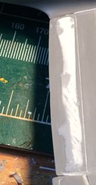
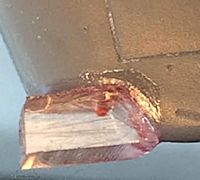
Also,
the kit tanks’ attachment tab will force the tanks into a nose-down attitude
instead of being parallel with the plane’s thrust line. Easy solution: make
a scribe mark about halfway down the front edge of the tank’s mounting tab.
Using a BAF - big a**ed file - file down the top of the tab so it slopes
down from the rear of the tab to the scribe mark. When you attach the tank,
it will be at the right angle. (droptanks; uncorrected tanks; corrected drop
tanks)
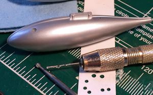 I
detailed the tanks by drilling a hole for the fuel line aft and slightly to
port of the mounting tabs. The filler caps are not represented on the tanks
- I used a small Dremel ball cutter in a pin vise to hand-mill a recess into
the tanks. Using a craft scrapbooking paper punch, I knocked out a couple of
styrene sheet discs and cemented one in each recess. After the tanks were
shot with primer and Metallizer non-buffing Aluminum Plate, the kit filler
point decals were applied and snuggled right into the caps.
I
detailed the tanks by drilling a hole for the fuel line aft and slightly to
port of the mounting tabs. The filler caps are not represented on the tanks
- I used a small Dremel ball cutter in a pin vise to hand-mill a recess into
the tanks. Using a craft scrapbooking paper punch, I knocked out a couple of
styrene sheet discs and cemented one in each recess. After the tanks were
shot with primer and Metallizer non-buffing Aluminum Plate, the kit filler
point decals were applied and snuggled right into the caps.
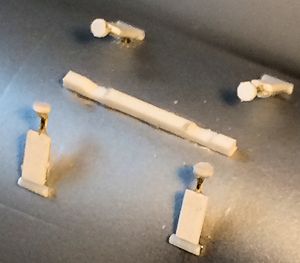
The wing
racks were also drilled on their port sides for the fuel lines from the
tanks, which were made from lead wire and installed later with the tanks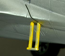 rear sway brace that swings down and contacts the
rear of the drop tank. The kit braces were a bit thick to my eye, so I made
new ones from .020 plastic rod with punched-disc hinge points and contact
cradles sliced from styrene c-channel stock. They were installed when I hung
the tanks near the end of the build.
rear sway brace that swings down and contacts the
rear of the drop tank. The kit braces were a bit thick to my eye, so I made
new ones from .020 plastic rod with punched-disc hinge points and contact
cradles sliced from styrene c-channel stock. They were installed when I hung
the tanks near the end of the build.
As Peter Falk used to say in ‘Columbo,’ one more thing. I used the Dremel and a small dental bit to mill out a recess under the port rear wing root for the T-bolt’s retractable step. That was built from plastic strip and also installed near the end of the build.
| COLORS AND MARKINGS |
Before
priming, I sprayed flat black on the windscreen framing. I also masked the
main canopy inside and out, spraying the interior frame with Model Master
Euro I Dark Green.
So ....
each color area was masked and painted separately before being masked over.
The wheel wells were outlined with tape and the inner gear door exteriors
and gear legs masked (to be painted later with Citadel acrylic Chainmail and
Testors Silver oleos) before getting the zinc chromate yellow treatment.
After that set, I used white poster putty and tape to mask off the wheel
wells. I then masked off everything but the empennage and wing stripes with
Glad Press ‘n Seal food wrap and tape strips before preshading the panel and
hinge lines with Model Master
Insignia Yellow. I then mixed up a 70/30 percent mix of Insignia Yellow and
flat white and misted it over the tail and upper wings
to get a sun-faded effect.
After masking the tail and stripes, I shifted the overall masking and outlined the fuselage anti-glare panel with tape strips. I also attached the cowling with poster putty and masked it to align with the fuselage panel. The panel was sprayed with Model Master ANA Olive Drab, allowed to set, and masked in the same manner as the wells and yellow ID markings. Yeah, it’s complicated, but it saved a lot of headaches - I promise. Everything was left to cure for a couple of days - mainly so I could recover from eye strain.
I used
Testors Metallizer Aluminum Plate buffing for the overall finish, with a few
panels painted in non-buffing Aluminum Plate. The oil cooler shutter areas
and the panel around the underfuselage turbo exhaust got sprayed with
Metallizer Burnt Metal. After an hour, I removed all the airframe masking
except for the windscreeen and did minor touchup to the yellow and OD areas
with a 3-O brush and paint. I attached the engine to the mail fuselage,
followed by the cowling, with super glue before masking the cowling opening.
The airframe then got a coat of Metallizer sealer in preparation for
decaling.
I used
the kit decals for the fuselage national marking since it was already
divided to fit across the fuselage side vents, and the kit decals also went
down well, Fuselage and wing stencil decals also came from the kit sheet.
After setting and a wipedown to remove excess solvent deposits and glue, I
applied another coat of sealer. After that set, I sprayed a very thin wash
of pale gray and mineral spirits over the upper surfaces.
 I used
artist’s acrylics mixed with Future/Pledge acrylic floor polish and
distilled water to make pinwashes for the panel lines - Payne’s grey for
overall airframe lines, raw umber for areas aft of the cowling. I then mixed
the leftover washes into a sludge for oil streaks, applying dots and
streaking them aft with a brush. Exhaust stains at the waste gates were
airbrushed with Model Master Panzer Dark Gray and later enhanced with
pastels.
I used
artist’s acrylics mixed with Future/Pledge acrylic floor polish and
distilled water to make pinwashes for the panel lines - Payne’s grey for
overall airframe lines, raw umber for areas aft of the cowling. I then mixed
the leftover washes into a sludge for oil streaks, applying dots and
streaking them aft with a brush. Exhaust stains at the waste gates were
airbrushed with Model Master Panzer Dark Gray and later enhanced with
pastels.
I
painted the gear struts - photos suggested lacquered struts and bare metal
oleos for Ns - and attached Ultracast diamond tread resin wheels (sprayed
flat black with aluminum hubs and treads weathered with Tamiya weathering
powders and chalk pastels). I also managed to lose both gear torque links to
the concrete floor monster, so I had to make new ones from bits of styrene
sheet and rod.
| FINAL BITS |
 New gun
blast tubes were fashioned from drilled sections of .040 styrene rod and
super-glued into the wings. IFF lights and the landing lamp were cemented in
place, and the masking was removed from the wingtip lights.
New gun
blast tubes were fashioned from drilled sections of .040 styrene rod and
super-glued into the wings. IFF lights and the landing lamp were cemented in
place, and the masking was removed from the wingtip lights.
The kit
lacks a ventral rack and sway braces as seen on many photos of wartime
P-47Ns, although a shallow depression where the hardpoint would be is molded
on the lower fuselage section of the lower wing part. I notched a short
length of .030 plastic square strip and cemented in in the
 recess to
represent the actual rack. Using photos and the Tamiya P-47M for reference,
I drilled locator holes for the sway brace arms .I then built the arms from
brass wire, grooved plastic strip and punched styrene discs before
super-gluing them in the holes.
recess to
represent the actual rack. Using photos and the Tamiya P-47M for reference,
I drilled locator holes for the sway brace arms .I then built the arms from
brass wire, grooved plastic strip and punched styrene discs before
super-gluing them in the holes.
I
installed the main canopy’s internal brace, and that made the canopy ride
too high on the fuselage. Solution: the internal brace has two small pips
underneath. Cut them off with nippers. The canopy will sit properly.
After final rigging and dorsal antenna installation, I made the AN/APS-13 radar antennas from loops and lengths of brass wire and attached them to the previously-drilled holes.
| CONCLUSIONS |
I know that
the P-47N is a relatively rare bird in aviation history, but this project really
made me wish that Tamiya had engineered an extra sprue and a couple of inserts
to turn their M kit into an N. That said, the Revell/Pro-Modeler kit is the best
game in town if you want a fairly accurate N. The shapes are there, and it
doesn’t take too much aftermarket to make it look good. But it will test your
skills and patience, and even the old Monogram T-bolts had sharper and cleaner
detail in most areas than does this bird.
If you’re
willing to do the work and if you treat it like a short-run kit, though, it will
reward you with a good representation of the ultimate combat Thunderbolt.
| REFERENCES |
February 2015
Kit courtesy
of my wallet.
If you would like your product reviewed fairly and fairly quickly, please contact the editor or see other details in the Note to Contributors.