Dragon 1/32 P-51D Mustang
| KIT #: | 3201 |
| PRICE: | $52.95 MSRP |
| DECALS: | Several options |
| REVIEWER: | Ralph B. Thompson |
| NOTES: |
Hobby Decal’s 1/32nd scale P-51D dry
transfers,
|
| HISTORY |
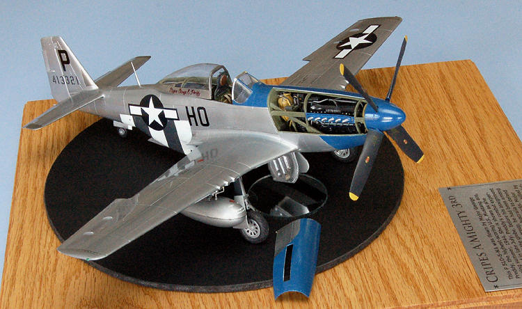
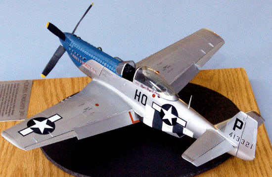
The history of the Mustang, including its debt to ex-Messerschmitt engineer Edgar Schmued at North American Aviation, has perhaps been as thoroughly documented as that of any aircraft built in an English-speaking nation. The machine chosen here, a P-51D-5NA, “Cripes A’Mighty 3rd,” was flown by Major George E. Preddy, the leading Mustang ace of World War II, in the summer of 1944.
| THE KIT |
Thanks to
DML/Dragon’s reputation for fine AFV kits and to the known shortcomings of other
Mustang kits in 1/32nd scale, Dragon’s first foray into large-scale
aircraft models was awaited breathlessly. The product itself fell short. Its
most obvious
 shortcoming
is its egregiously overdone surface treatment. Further examination by subsequent
reviewers and builders has revealed additional errors both in kit engineering
and in substance. They include: a “backwards” propeller, a cockpit floor that
fails to reach the sidewalls of the cockpit, apparently incorrectly sized flaps
and ailerons, inadequate landing gear, incorrect main wheel wells, and incorrect
MLG doors.
shortcoming
is its egregiously overdone surface treatment. Further examination by subsequent
reviewers and builders has revealed additional errors both in kit engineering
and in substance. They include: a “backwards” propeller, a cockpit floor that
fails to reach the sidewalls of the cockpit, apparently incorrectly sized flaps
and ailerons, inadequate landing gear, incorrect main wheel wells, and incorrect
MLG doors.
Tom Cleaver’s initial review of Dragon’s P-51 here on Modeling Madness both alerted me to some of the build issues I’d confront and inspired me to give the kit a go. His recent build article on Dragon’s “early” P-51D moved me to submit this account of my experience with a Dragon Mustang. A couple caveats: (1) I do not pretend to set up shop as a Mustang expert. My resources, skills and knowledge are limited. I have done what I could with what I had. (2) In no way am I suggesting that Dragon’s Mustang kits are unbuildable. For the most part they fit together nicely. Builders hoping for an accurate P-51, however, have their work cut out for them.
| CONSTRUCTION |
My first task
was to improve the rendering of the model’s surface by obliterating most of the
“surface detail,” including all rivets, several panel lines, and all oversized
raised details I could identify. I have found no easy way to tackle this kind of
job. All of my attempts have required time, patience and diligence. In this
instance I addressed the rivets and unwanted panel lines with 3M’s Acryl Green,
a pinhole filler for auto body finishes. I cut the filler about 1/1 with 91%
isopropyl alcohol to get it into the rivet cavities and applied additional coats
over several days to cope with shrinkage as the filler dried.
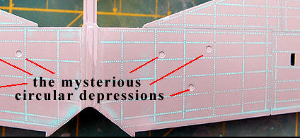
Each major
airframe element received additional attention. While working on the wings, I
filled the slots for the zero-length rocket launchers (the -5 NA’s did not have
them) and filled the two triangular sets of mysterious round cavities on the
bottoms of the wings.
 Using
a micro-chisel, I removed the raised aileron hinge details and replaced them
with more petite versions made from styrene sheet. The wingtips, which in the
kit appear as raised detail, were sanded flush with the wing surface. The
fairings for the machine-gun blast tubes were also pared down to a more
realistic size. Since I was building an “early” P-51D, I had to remove the
diagonal strake ahead of the kit’s vertical fin and fill the resulting hole with
a styrene patch. At the same time, I removed the raised detail at the root of
the horizontal tail (which is supposed to represent the sheet-metal fairing
covering the area.) I then rescribed the panel lines and the fasteners. When the
time came to join the major components, I would face additional issues involving
the wing roots, flaps, ailerons and elevators. These matters are discussed
below.
Using
a micro-chisel, I removed the raised aileron hinge details and replaced them
with more petite versions made from styrene sheet. The wingtips, which in the
kit appear as raised detail, were sanded flush with the wing surface. The
fairings for the machine-gun blast tubes were also pared down to a more
realistic size. Since I was building an “early” P-51D, I had to remove the
diagonal strake ahead of the kit’s vertical fin and fill the resulting hole with
a styrene patch. At the same time, I removed the raised detail at the root of
the horizontal tail (which is supposed to represent the sheet-metal fairing
covering the area.) I then rescribed the panel lines and the fasteners. When the
time came to join the major components, I would face additional issues involving
the wing roots, flaps, ailerons and elevators. These matters are discussed
below.
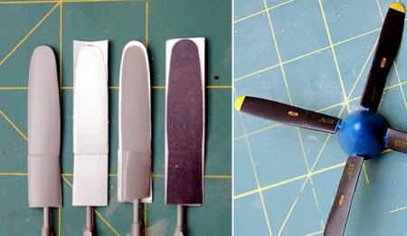 I had ample time to work on details between applications of filler and
sanding sessions for the exterior. I rebuilt the propeller, modified and
detailed the engine, and created a new cowling for it. I detailed the cockpit
and modified the cockpit/radiator assembly to fit the fuselage. Finally I
tackled the undercarriage, scratchbuilding new wheel wells, new main landing
gear and new main landing gear doors.
I had ample time to work on details between applications of filler and
sanding sessions for the exterior. I rebuilt the propeller, modified and
detailed the engine, and created a new cowling for it. I detailed the cockpit
and modified the cockpit/radiator assembly to fit the fuselage. Finally I
tackled the undercarriage, scratchbuilding new wheel wells, new main landing
gear and new main landing gear doors.
Continuing aft, I decided to replace the thick clear styrene cowling Dragon had
provided as a “see-through” option to display the Merlin engine. I used the kit
pieces as masters for male resin molds and vacuformed replace-ment panels using
.020” styrene. I adjusted the support frames on the engine mount pieces to
compensate for the much thinner panels, moving them out slightly and applying
the appropriate facing from the Eduard photo-etch set.
Then I
turned to the engine
 proper.
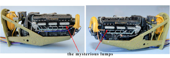
Right away I was scratching my head about the three rectangular lumps on each
side of the engine block, where the exhaust ports would be ordinarily. They are
there because Dragon’s Merlin has been made very undersized in order to fit
beneath those thick clear styrene cowl panels.
One mounts the
exhaust stacks on the lumps so they will extend outward far enough to project
through the openings in the cowl. I was not up to scratch-building a 1/32nd
scale Merlin, but I decided I could improve on what was offered. I rebuilt the
squat valve-covers. Then I went a l
proper.
Right away I was scratching my head about the three rectangular lumps on each
side of the engine block, where the exhaust ports would be ordinarily. They are
there because Dragon’s Merlin has been made very undersized in order to fit
beneath those thick clear styrene cowl panels.
One mounts the
exhaust stacks on the lumps so they will extend outward far enough to project
through the openings in the cowl. I was not up to scratch-building a 1/32nd
scale Merlin, but I decided I could improve on what was offered. I rebuilt the
squat valve-covers. Then I went a l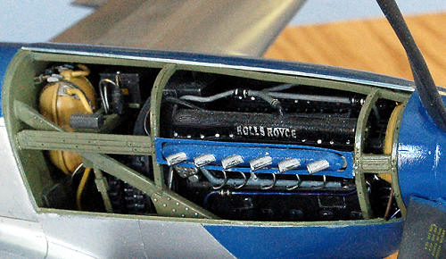 ittle
AMS. I punched 015” diameter plugs out of a sheet of soft aluminum to use as
conspicuous bolt heads surrounding those newly-refined valve covers and, in
sheer defiance of accuracy, attached Eduard’s “Rolls-Royce” placards to the
valve-covers of this Packard-built Merlin. After I had assembled, wired, and
plumbed the engine I installed the other Eduard parts for the engine
compartment; and scratchbuilt some missing items that should be found in front
of the firewall. The result
looks
plausible to me, if somewhat anemic.
ittle
AMS. I punched 015” diameter plugs out of a sheet of soft aluminum to use as
conspicuous bolt heads surrounding those newly-refined valve covers and, in
sheer defiance of accuracy, attached Eduard’s “Rolls-Royce” placards to the
valve-covers of this Packard-built Merlin. After I had assembled, wired, and
plumbed the engine I installed the other Eduard parts for the engine
compartment; and scratchbuilt some missing items that should be found in front
of the firewall. The result
looks
plausible to me, if somewhat anemic.
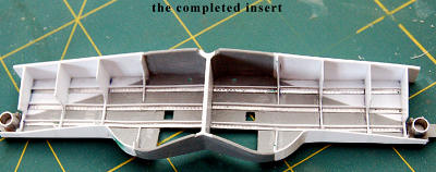
My one clear
pleasure in building this Mustang was constructing the cockpit. Dragon p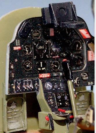 rovides
a decent set of bare bones, if you discount the matter of the floor and
associated bulkheads not reaching the sidewalls of the fuselage. Simply adding
styrene card symmetrically and test-fitting until everything makes contact takes
care of the problem. My revised cockpit insert lined up perfectly with the
mounting guides inside the fuselage halves.
rovides
a decent set of bare bones, if you discount the matter of the floor and
associated bulkheads not reaching the sidewalls of the fuselage. Simply adding
styrene card symmetrically and test-fitting until everything makes contact takes
care of the problem. My revised cockpit insert lined up perfectly with the
mounting guides inside the fuselage halves.
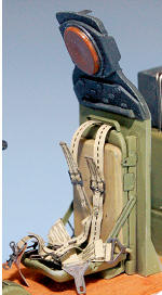 Eduard’s interior photo-etch set offers an abundance of small detail,
even providing toggle switches (!) on the instrument panel and the electronics
control panels and a pair of wing-nuts to hold down one of the “black boxes” aft
of the pilot’s seat. Much of the photo-etch is pre-printed in color. This
feature simplifies detailing considerably and results in a stunning array of
instruments.
Since the
assembly in question also includes the Mustang’s radiator, I added Eduard’s
photo-etched radiator faces at this stage and refined the adjustable
exhaust-duct by thinning it.
Eduard’s interior photo-etch set offers an abundance of small detail,
even providing toggle switches (!) on the instrument panel and the electronics
control panels and a pair of wing-nuts to hold down one of the “black boxes” aft
of the pilot’s seat. Much of the photo-etch is pre-printed in color. This
feature simplifies detailing considerably and results in a stunning array of
instruments.
Since the
assembly in question also includes the Mustang’s radiator, I added Eduard’s
photo-etched radiator faces at this stage and refined the adjustable
exhaust-duct by thinning it.
While I was
building the cockpit I kept thinking about Dragon’s thick, clear styrene
glazing. I decided to use the windscreen
piece, which called for some careful filling and fitting to blend it with the
fuselage, but the canopy had to go. I used the Dragon part as a master for a
resin male mold, over which I vacuformed a new canopy from .010” thermoform
plastic. At the same time, I also vacuformed an opaque canopy from .015”
styrene, to be used as a mask for the cockpit enclosure during the rest of the
build. I then carefully cut away the “bubble“ part of the original Dragon
canopy, leaving just the frame. This remnant fit perfectly insi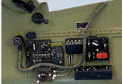 de
my new clear bubble and provided a three-dimensional canopy frame to boot. So
what if the replacement canopy was roughly .010” oversize? Close enough for
government work, I figured. While I was at it, I decided to refine the “Major
George E. Preddy” legend which appears on the canopy frame. I scanned the
original decal at high resolution and used Photoshop to brighten the colors and
sharpen the definition. I printed the result on inkjet decal paper, sealed it
and put it in place.
de
my new clear bubble and provided a three-dimensional canopy frame to boot. So
what if the replacement canopy was roughly .010” oversize? Close enough for
government work, I figured. While I was at it, I decided to refine the “Major
George E. Preddy” legend which appears on the canopy frame. I scanned the
original decal at high resolution and used Photoshop to brighten the colors and
sharpen the definition. I printed the result on inkjet decal paper, sealed it
and put it in place.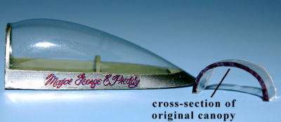
Now
I had to cope with the undercarriage, an aspect of the kit one build-reviewer
charitably described as “a train wreck.” The most complex problem would be the
MLG wells. Dragon, like other kit producers, rendered these features with a rear
wall that follows the line of the cover for the landing gear leg. The actual
wheel well cavity, as many reviewers have noted, extends back to the main wing
spar.
 I began by making masking tape patterns for the front walls of the MLG
well (inside the lower wing part) and cut replacement parts from .010” styrene.
These would be attached to part E25 (Dragon’s wheel well interior) in due time.
Then I dremeled the molded-in walls off the lower wing part. Next, I removed all
spurious detail from part E25 after marking the wing rib locations for future
reference. I cut out the rectangular openings in the roof of the well through
which coolant hoses can be seen and from which many hydraulic lines emerge. I
also replaced kit part I15, the divider between the wells, with sheet styrene,
extended the wheel-well roof aft to the line of the main spar, and added the
front walls (the styrene pieces mentioned p
I began by making masking tape patterns for the front walls of the MLG
well (inside the lower wing part) and cut replacement parts from .010” styrene.
These would be attached to part E25 (Dragon’s wheel well interior) in due time.
Then I dremeled the molded-in walls off the lower wing part. Next, I removed all
spurious detail from part E25 after marking the wing rib locations for future
reference. I cut out the rectangular openings in the roof of the well through
which coolant hoses can be seen and from which many hydraulic lines emerge. I
also replaced kit part I15, the divider between the wells, with sheet styrene,
extended the wheel-well roof aft to the line of the main spar, and added the
front walls (the styrene pieces mentioned p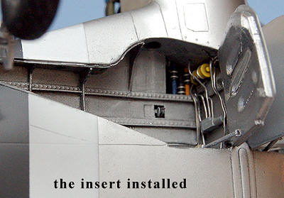 reviously)
and the back walls. I now had a boxlike element resembling an aftermarket
drop-in wheel well replacement. Temporarily assembling this structure with the
wings and fuselage, I installed the MLG mounts at the required 11 degree rake
angle, using a jig. The mounts themselves are aluminum tubing sockets that also
serve as the “cuffs” at the top of each MLG leg. They are held in place with
epoxy resin to provide sturdy, secure attachment points. After I had fitted the
mounts, I removed the box, detailed it with ribs, simulated riveted stringers
using embossed aluminum salvaged from a soda can, and devised hydraulic
equipment from scrap styrene, bits of brass and fine gauge solder. The result
may not have been utterly accurate, but I considered it, like my Merlin,
plausible.
reviously)
and the back walls. I now had a boxlike element resembling an aftermarket
drop-in wheel well replacement. Temporarily assembling this structure with the
wings and fuselage, I installed the MLG mounts at the required 11 degree rake
angle, using a jig. The mounts themselves are aluminum tubing sockets that also
serve as the “cuffs” at the top of each MLG leg. They are held in place with
epoxy resin to provide sturdy, secure attachment points. After I had fitted the
mounts, I removed the box, detailed it with ribs, simulated riveted stringers
using embossed aluminum salvaged from a soda can, and devised hydraulic
equipment from scrap styrene, bits of brass and fine gauge solder. The result
may not have been utterly accurate, but I considered it, like my Merlin,
plausible.
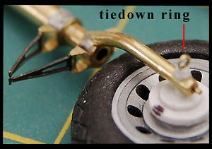 Now for the undercarriage itself. The Mustang’s landing gear legs are
simple structures, easy to reproduce in small diameter rod and tubing. I built
mine of brass and used the torque scissors from the Eduard exterior set. The
tie-down ring is a thin slice of fine brass tubing. The legs fit snugly into the
aluminum sockets of the wheel well replacement, providing a sturdy base. Making
the main wheels turned out to be rather fussy. As in many large-scale
Chinese-made aircraft kits, two styrene parts form the wheel hub, onto which one
then fits a vinyl tire. In my kit the tires, while of the correct outer
diameter, had an inner diameter too large for the hubs. I glued thin strips of
.010” styrene to the surfaces where th
Now for the undercarriage itself. The Mustang’s landing gear legs are
simple structures, easy to reproduce in small diameter rod and tubing. I built
mine of brass and used the torque scissors from the Eduard exterior set. The
tie-down ring is a thin slice of fine brass tubing. The legs fit snugly into the
aluminum sockets of the wheel well replacement, providing a sturdy base. Making
the main wheels turned out to be rather fussy. As in many large-scale
Chinese-made aircraft kits, two styrene parts form the wheel hub, onto which one
then fits a vinyl tire. In my kit the tires, while of the correct outer
diameter, had an inner diameter too large for the hubs. I glued thin strips of
.010” styrene to the surfaces where th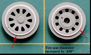 e
tires were to seat until the tires would meet them properly.
e
tires were to seat until the tires would meet them properly.
Finally I had to
remake the two inner landing gear doors. I could have built ”Cripes A’Mighty 3rd”
with these doors in the up position, obscuring all the detail I had just
lavished on the MLG wells, but I wanted to fix them. The MLG door on a Mustang
is a sort of sandwich, with a thin outer “skin” layer following the shape of the
wheel well opening and a thicker, inner component having a shallow, roughly
circular concave area on its face to accommodate the wheel.
Three long parallel depressions in this face stiffen the whole affair.
The exterior of the Dragon doors is the right shape, but all of the interior
details are wrong. I began by removing everything but the skin from the Dragon
doors. Returning to my Hasegawa donor-Mustang kit, I ground away the exteriors
of its MLG doors. I now had MLG door interiors on which the deep parallel
depressions were headed in the right d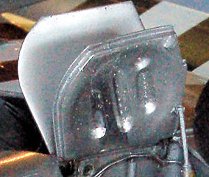 irection.
After I matched everything up, refined fit and shape where needed, and added the
various Eduard details, I had a pair of decent-looking doors. I finished them
off with a polished aluminum strip (Bare Metal Foil chrome) down the middle of
each, the “scrub strip” along which the tire (I gather) slid upon retraction and
extension. I doubt the real “Cripes A’Mighty 3rd” sported this
refinement. On the other hand, my model already had a “Rolls-Royce,” so . . .
irection.
After I matched everything up, refined fit and shape where needed, and added the
various Eduard details, I had a pair of decent-looking doors. I finished them
off with a polished aluminum strip (Bare Metal Foil chrome) down the middle of
each, the “scrub strip” along which the tire (I gather) slid upon retraction and
extension. I doubt the real “Cripes A’Mighty 3rd” sported this
refinement. On the other hand, my model already had a “Rolls-Royce,” so . . .
After I had
closed up the fuselage halves and the wings, I began assembling the major
airframe elements. In the process I discovered other matters that needed
attention. I had been using the Watanabe 1/40th scale drawings from
The Great Book of World War II Airplanes
throughout this project. I scanned my finished wing and horizontal tail into
my computer as JPG’s and compared them with a scaled-up Photoshop overlay of the
Watanabe plan view. The elevators appeared too broad in chord. The ailerons were
slightly large in both span and chord. The flaps, though slightly short in span,
scaled out at 5 ¼’ too broad, producing a 25% increase in flap area.
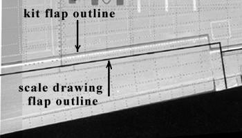 Moreover,
the flap root was rendered as curved, rather than straight. The sheet-metal
fairing that surrounds the wing root does present a curved metal flange that
overlaps the slight gap between the flap root and the wing structure proper, a
flange I overlooked in my revision. Nonetheless, the flap itself is trapezoidal.
Dragon’s portrayal of the fairing strip on the fuselage poses further
complications by showing the juncture of trailing edge and fuselage side as
curiously bulged, and by presenting the fairing strip itself as raised above
skin level like the one I have already mentioned
Moreover,
the flap root was rendered as curved, rather than straight. The sheet-metal
fairing that surrounds the wing root does present a curved metal flange that
overlaps the slight gap between the flap root and the wing structure proper, a
flange I overlooked in my revision. Nonetheless, the flap itself is trapezoidal.
Dragon’s portrayal of the fairing strip on the fuselage poses further
complications by showing the juncture of trailing edge and fuselage side as
curiously bulged, and by presenting the fairing strip itself as raised above
skin level like the one I have already mentioned
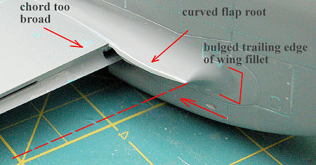 on
the vertical fin.
on
the vertical fin.
The remedy was simple. I modified the flaps and ailerons to match the reference drawings, then modified the bays to accept them. To fix the flap well, I made aluminum angles from soda-can aluminum on my Etch-Mate, fastened them with cyanoacrylate to the front of the well top and bottom, and used them to support strips of .010” styrene, butted to the skin of the wing with Tamiya extra-thin cement. Then I dry-fitted the completed ailerons and flaps until they fit properly. The elevators were simply trimmed at the trailing edge. While I was at it, I also thinned the trailing edges of all the control surfaces.
| COLORS & MARKINGS |
By choosing
“Cripes A’Mighty 3rd” as my subject I had committed myself to a color
scheme including aluminum lacquer, bare metal, the famous blue nose and, on the
underside, D-Day invasion stripes. I sprayed several coats of Mr. Surfacer 1000
thinned with isopropyl alcohol, then a couple coats of Alclad II Microfiller to
deal with scribing slips and stubborn rivet cavities. I finished the removable
cowl pieces separately, in Alclad’s Polished Aluminum. Later, they would be put
in place to receive the blue nose trim (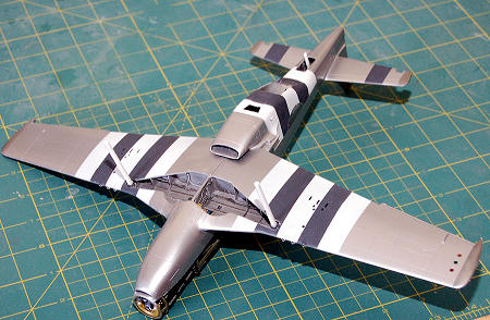 Model
Master True Blue, deepened to taste with Model Master Insignia Blue), then
removed again for decaling and additional work. Meanwhile, the airframe received
three coats of Alclad II Aluminum mixed 3:1 with Polished Aluminum to lighten
the tone. After the Alclad II had cured I masked and painted the invasion
stripes. I understand that these markings were none too fastidiously applied on
many real aircraft, so I felt justified in being a little rough and ready
myself. The white is Tamiya’s fine white primer. It dries fast and covers well.
The black is Testor’s RLM 66 Schwarzgrau deepened with a bit of flat black.
After the stripes had
set up, I added other aluminum tones to various panels and touched up as many
glitches as I could find. Jerry Crandall’s EagleCals went on easily and
performed beautifully. I added various stencils from Hobby Decal’s 1/32nd
scale dry transfer set for the Mustang. Then everything was sealed with a
thinned coat of Future. Since I knew that my subject had been spiffed up for the
Brass Hats on the day my reference photos were taken, I did not weather the
model.
Model
Master True Blue, deepened to taste with Model Master Insignia Blue), then
removed again for decaling and additional work. Meanwhile, the airframe received
three coats of Alclad II Aluminum mixed 3:1 with Polished Aluminum to lighten
the tone. After the Alclad II had cured I masked and painted the invasion
stripes. I understand that these markings were none too fastidiously applied on
many real aircraft, so I felt justified in being a little rough and ready
myself. The white is Tamiya’s fine white primer. It dries fast and covers well.
The black is Testor’s RLM 66 Schwarzgrau deepened with a bit of flat black.
After the stripes had
set up, I added other aluminum tones to various panels and touched up as many
glitches as I could find. Jerry Crandall’s EagleCals went on easily and
performed beautifully. I added various stencils from Hobby Decal’s 1/32nd
scale dry transfer set for the Mustang. Then everything was sealed with a
thinned coat of Future. Since I knew that my subject had been spiffed up for the
Brass Hats on the day my reference photos were taken, I did not weather the
model.
| FINAL CONSTRUCTION |
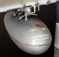 Dragon’s armament and stores are among this kit’s nicer features. The
Browning M2’s are pleasingly crisp. The 500 lb bombs and the rockets make up
nicely, especially when enhanced by Eduard’s photoetched fins. Dragon also
includes sets of both 85 gallon and 110 gallon drop tanks. Most of these items
went into my spares box, but I plumbed the 85 gallon tanks, fitted them out with
their special decals from the EagleCals set,
and
mounted them. I used short lengths of hypodermic tubing for the blast tubes of
the six 50’s and for the gun barrels themselves. Also at this stage I installed
the exhausts, the landing light, the undercarriage and its doors, navigation
lights, the antenna, and the canopy, which I had protected until now in a small
Ziploc pouch. I then fashioned a base using red oak, foam board and a small
circular mirror, and made a cover from 1/8th inch clear acrylic
sheet. Finally, I produced the legend as an inkjet decal and applied it to a
rectangle of .016” aluminum.
Dragon’s armament and stores are among this kit’s nicer features. The
Browning M2’s are pleasingly crisp. The 500 lb bombs and the rockets make up
nicely, especially when enhanced by Eduard’s photoetched fins. Dragon also
includes sets of both 85 gallon and 110 gallon drop tanks. Most of these items
went into my spares box, but I plumbed the 85 gallon tanks, fitted them out with
their special decals from the EagleCals set,
and
mounted them. I used short lengths of hypodermic tubing for the blast tubes of
the six 50’s and for the gun barrels themselves. Also at this stage I installed
the exhausts, the landing light, the undercarriage and its doors, navigation
lights, the antenna, and the canopy, which I had protected until now in a small
Ziploc pouch. I then fashioned a base using red oak, foam board and a small
circular mirror, and made a cover from 1/8th inch clear acrylic
sheet. Finally, I produced the legend as an inkjet decal and applied it to a
rectangle of .016” aluminum.
| CONCLUSIONS |
So what’s the
verdict? Did I expect too much, or is the Dragon kit a bust? I have to say there
was some of each in the mix. When I build models, I want to have fun. But since
I also build things for others to view, I wa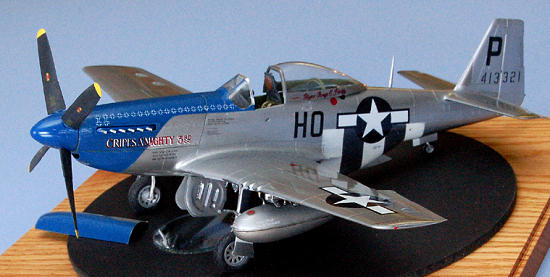 nt
the end result to be useful as an expression of the original. I believe that a
model succeeds only to that extent to which its audience buys into it, and for
me, Dragon’s 1/32 scale P-51D Mustang kit is not credible. It looks as though
Dragon couldn’t decide whether to produce a model or a toy. Serious attempts to
render details stand side-by-side with needless distortions, gratuitous working
features, odd mistakes (the propeller, the landing gear doors, the mysterious
circular depressions on the underside of the wing), and the rivets. Nonetheless,
one can get beyond them. The kit is not unbuildable. A slew of aftermarket
products awaits the AMS sufferer’s dollar, among them the excellent Eduard brass
and EagleCals decals I put into this effort. Meanwhile, for those of us who
delight in simply assembling and painting a model, then playing with it, the
Dragon kit is just fine. And their number must be legion: the kit’s still on the
market and evidently people are buying it.
nt
the end result to be useful as an expression of the original. I believe that a
model succeeds only to that extent to which its audience buys into it, and for
me, Dragon’s 1/32 scale P-51D Mustang kit is not credible. It looks as though
Dragon couldn’t decide whether to produce a model or a toy. Serious attempts to
render details stand side-by-side with needless distortions, gratuitous working
features, odd mistakes (the propeller, the landing gear doors, the mysterious
circular depressions on the underside of the wing), and the rivets. Nonetheless,
one can get beyond them. The kit is not unbuildable. A slew of aftermarket
products awaits the AMS sufferer’s dollar, among them the excellent Eduard brass
and EagleCals decals I put into this effort. Meanwhile, for those of us who
delight in simply assembling and painting a model, then playing with it, the
Dragon kit is just fine. And their number must be legion: the kit’s still on the
market and evidently people are buying it.
| REFERENCES |
January 2011
If you would like your product reviewed fairly and quickly, please contact me or see other details in the Note to Contributors.