Revell 1/48 PT-17 Kaydet
| KIT #: | ` |
| PRICE: | ` |
| DECALS: | ` |
| REVIEWER: | Michael Rhode |
| NOTES: |
. |
| HISTORY |
As early as 1933 the Stearman Aircraft Company began design and construction of a new training air plane.
Built as a private venture the first flight took place in December 1933 and the Stearman X 70 was submitted as a contender in 1934 to meet a US Army Air Corps requirement for a new primary trainer. However, it was the US Navy to show positive interest in the new design and- in early 1935- contracted for the supply of 61 Stearman Model 70's under the designation NS-1.
 The X 70 supplied to the
USAAC for evaluation was subjected to further testing and in early 1936 the
USAAC contracted for the supply of 26 aircraft under the designation PT 13 (
Primary Trainer 13). These, powered by a 215 hp
Lycoming R 680-5 radial engine were the first of the Stearman 75's.
The X 70 supplied to the
USAAC for evaluation was subjected to further testing and in early 1936 the
USAAC contracted for the supply of 26 aircraft under the designation PT 13 (
Primary Trainer 13). These, powered by a 215 hp
Lycoming R 680-5 radial engine were the first of the Stearman 75's.
In 1939 the Stearman Aircraft Company became identified as the Wichita Division of the Boeing Airplane Company and with the arrival of WW 2 the fortunes of war were to bring Boeing contracts for thousands of Stearman designed trainers.
This attractive two seater bi plane was of mixed construction. The single bay wings and the tail plane were made of wood with fabric covering. The fuselage was a welded steel tube structure covered with fabric and aluminium panels. The landing gear was nonretractable tail wheel type. The divided cantilever main units had oleo spring shock absorbers covered by fairings.
Main production lasted until 1945 with over 10,000 units built.
| THE KIT |
The kit consists of 83 nicely detailed and crisp parts on 10 sprues and one sprue of clear parts. Decals for two versions are included. The instructions are well laid out and do include an extra page dedicated to the rigging of the model.
| CONSTRUCTION |
 I always start with
separating all the parts from their respective sprues, remove any flashes or
signs of mold shift and dry fit parts( where necessary) before assembly.
I always start with
separating all the parts from their respective sprues, remove any flashes or
signs of mold shift and dry fit parts( where necessary) before assembly.
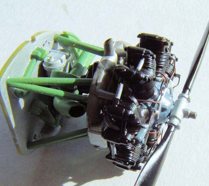
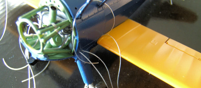
As you can see I have decided to add an important detail to the engine and this is the distributor ring for the ignition leads. I fashioned this item out of .5 mm styrene rod and the ignition leads were made from thin copper wire. The second set of leads will be added later. The dry fitting of the engine parts revealed the the exhaust pipe studs were a tat short and I remedied this problem by adding 1.0 mm styrene rod to close the gap to the exhaust ports on the cylinder heads.
 I assembled
the internal tube structure and upper and lower wings. Minute amounts of Tamiya
filler were needed to fill and clean up the seams.
I assembled
the internal tube structure and upper and lower wings. Minute amounts of Tamiya
filler were needed to fill and clean up the seams.
At this stage I drilled all the holes for the rigging wire attachment points using a .10 mm dental technicians drill bit.
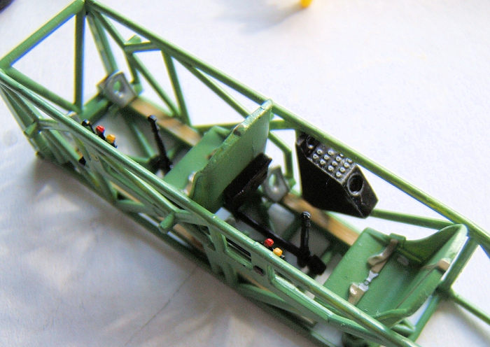
Stage 2-3-4:
Engine and engine rear compartment, fuselage internal structure incl seats and controls, the internal fuselage keel surfaces and wheels have been painted.
The fuselage and engine support frame have been assembled.
Here I made an effort to scratch build wiring looms, oil pipes and the fuel lines connecting to the upper wing tank. My intention is to depict the aircraft sitting on the tarmac during maintenance. The panels covering the area behind the engine will not be installed exept one panel with the carburetor air intake.
The starboard panel was carefully separated and on the port side panel I drilled out the openings for the oil tank filler cap and the inertia crank starter.
The lower wing and tail plane are now in place.
Stage 5:
 Fuselage, N
struts and wings have been painted. Now ir was time to start pre rigging the
model. For this I used a elastic knitting line used in the textile industry.
This material has a flat profile and lends itself perfectly to look like
aerofoil shaped rigging wire.
Fuselage, N
struts and wings have been painted. Now ir was time to start pre rigging the
model. For this I used a elastic knitting line used in the textile industry.
This material has a flat profile and lends itself perfectly to look like
aerofoil shaped rigging wire.
I deliberately did not
install the N struts in order to give myself more space to make step two of the
rigging process easier. I started with attaching the upper wing rigging wires
followed by the main wing and tail plane wires.
Then 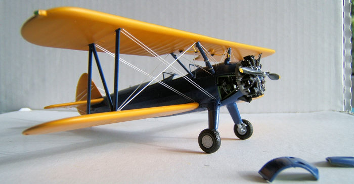 the upper wing was attached to the cabane struts with CA glue and continued
with the second stage of the rigging process.
the upper wing was attached to the cabane struts with CA glue and continued
with the second stage of the rigging process.
When all the rigging was in place I finally added the outer N struts.
Stage 6:
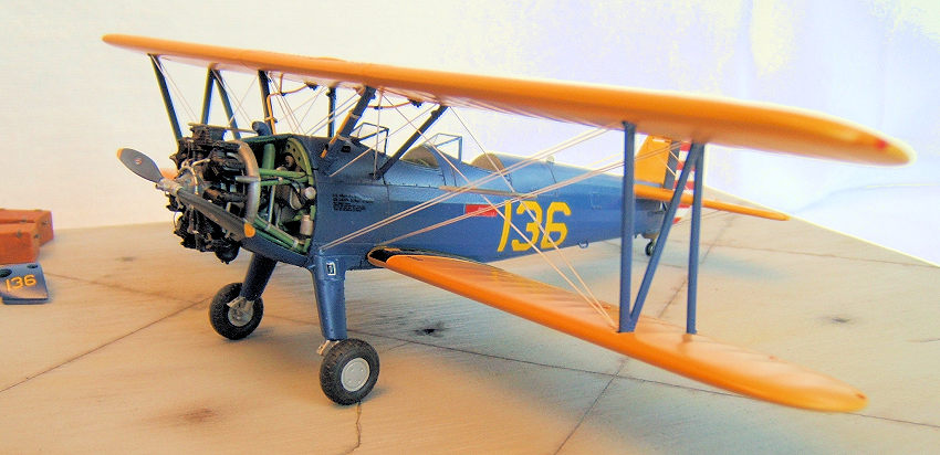
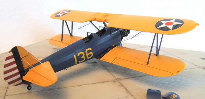
Here we come to applying the decals. After setting I sealed the decals with a thin coat of gloss clear. Weathering was done using pastel colours. The paint scheme and markings depict an aircraft used by the USAAC in 1941. Tamiya and Humbrol Enamels were used to paint the model.
| CONCLUSIONS |
Revell has given us a superb kit of one of the most famous Primary Trainer bi planes in Aviation History. Overall fit and detailing are very good indeed .The quality of the decals supplied with the kit are good and went on well.
31 August 2017
Copyright ModelingMadness.com
If you would like your product reviewed fairly and fairly quickly, please contact the editor or see other details in the Note to Contributors.
Back to the Main Page Back to the Review Index Page Back to the Previews Index Page