Hobby Boss 1/48 FM-2 Wildcat
|
KIT #: |
80330 |
|
PRICE: |
$34.00 SRP |
|
DECALS: |
? |
|
REVIEWER: |
Joe
Lyons |
|
NOTES: |
Eduard belts and Fast Frames canopy set
used |
The Grumman F4F-series was the most important
Allied carrier fighter from 1940 into 1943, participating in all the great
pacific carrier battles as well as extended FAA service in the
Atlantic
and the
Mediterranean.
Its first-line days seemed numbered as the Hellcat and Corsair entered service,
however the wartime escort carrier program, born of necessity to prosecute the
anti-submarine war in the Atlantic and then many other tasks, gave the elder
Grumman a new lease on life on the small decks. To free up factory space for
Hellcat, Grumman found a production partner in the auto industry to license
build the F4F. General Motors set up a production facility at its
Linden,
NJ
plant for the now-renomenclatured Wildcat. The ‘Eastern Aircraft Division’ of GM
got its first contract for FM-1s in April 1942 and production deliveries began
in early 1943.
 Eastern shifted production to the
FM-2 in September 1942. Based on a Grumman initiative to reduce the weight of
the basic F4F, the FM-2 used the Wright R-1820-56 with 150 hp more than the P&W
R-1830 used in all previous USN F4Fs. The new engine was also lighter than its
predecessor, which with airframe changes resulted in an overall weight savings
of about 500 lbs compared to the F4F-4.
Eastern shifted production to the
FM-2 in September 1942. Based on a Grumman initiative to reduce the weight of
the basic F4F, the FM-2 used the Wright R-1820-56 with 150 hp more than the P&W
R-1830 used in all previous USN F4Fs. The new engine was also lighter than its
predecessor, which with airframe changes resulted in an overall weight savings
of about 500 lbs compared to the F4F-4.
A significant change to the FM-1,
carried over to the FM-2, was the reduction of the armament to four .50 mgs. The
initial Wildcats had four guns, but six were introduced in the F4F-4. This move
infuriated USN fleet fighter pilots who (1) were quite happy with the firepower
of the four guns, (2) resented the reduced firing time caused by spreading the
same rounds to six guns and (3) did not like the additional weight in an
airframe they already thought was underpowered. An entire chapter of Reference f
is devoted to this and other Wildcat issues after the
Battle
of Midway.
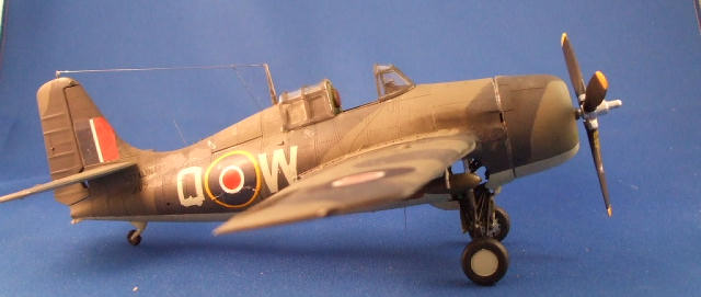
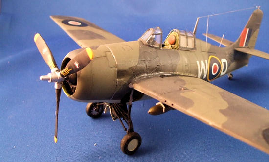
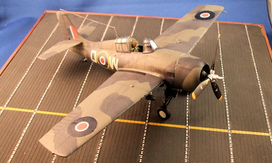
The FAA would receive 340 of the –2,
employing them in 22 squadrons as the Wildcat Mk VI. It was the only foreign
operator of the Wildcat series. The FAA Mk VI replicated by this model is JV735
(Q W) of 853 Squadron, operating from HMS Queen in March 1945.
No information on what comes in the box was supplied. Ed
The real stories of kit assembly are:
-
The
cockpit, with its bulkheads at the rear and instrument panel in front.
-
The
engine and accessory/landing gear bay, to include engine and accessory, part
F45
-
The
landing gear assemblage.
Cockpit
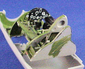 The cockpit is as good as it’s going to get in
an injection-molded kit. There are good photo references of Wildcat cockpits and
I think this one touches all the bases. The basic instrument panel however looks
to be too shallow, a characteristic I think it shares with the
TAM
kit. I fixed this with a ProModeller decal sheet of USN wartime fighter panels,
using the FM-2 panel cut from the sheet with its backing. The side panels,
rudder pedals and central console and the rest need only paint. I did add Brit
Sutton harnesses to the seat from an Eduard PE set.
The cockpit is as good as it’s going to get in
an injection-molded kit. There are good photo references of Wildcat cockpits and
I think this one touches all the bases. The basic instrument panel however looks
to be too shallow, a characteristic I think it shares with the
TAM
kit. I fixed this with a ProModeller decal sheet of USN wartime fighter panels,
using the FM-2 panel cut from the sheet with its backing. The side panels,
rudder pedals and central console and the rest need only paint. I did add Brit
Sutton harnesses to the seat from an Eduard PE set.
Landing Gear Bay et al
This is assemblage is a bit of a challenge. The
instructions do not really offer a sequence of assemble; here is mine:
1.
Parts F9/10 (intercoolers) do not apply to the
single stage Cyclone supercharger and should go to the spares box.
2.
Assemble F15 to bulkhead F47 – allow to
completely set/dry
3.
Install F37, its aft end on F47, its fore end
mating with F15 – note the notches on this part that fit onto F15.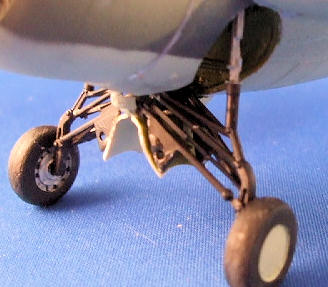
4.
Install F13 onto F47 and F15
NOTE: As in most complex builds like
this, the scale parts (and they are quite good) do not offer much gluing surface
– take it slowly.
Next, install cockpit assemblage
onto part B2. The fit is a bit fiddly, as the cockpit-B2 joint also does not
offer much gluing surface. Dry fit – dry fit – dry fit.
The wheel bay assemblage comes next
and its fit is determined by how F47 fits B2. The ‘scalloped’ cut outs for the
retracted wheels define this fit.
Paint and assemble the engine parts
and F45, then install onto B2.
Now, you have to marry all this
‘stuff’ to the assembled fuselage halves. The fit is not good; there are a lot
of gaps, and I ended up do a bit of clamping. Next time I would spend time (a
lot of time) finding the oversize joining surfaces and dealing with them.
Landing Gear
The kit parts for the gear are fragile,
exquisite and accurate. Once again the kit assembly sequence and supporting
drawings are bit vague. I did it their way at first, but would recommend this
way:
-
Follow the kit directions for F34 and F43 – hold off on the wheels for a
bit.
-
Install F18 as shown – do not get confused as I did on which way is up.
-
D
 O
NOT install doors F24/F25 at this time.
O
NOT install doors F24/F25 at this time.
-
Install F44 as directed, but note the notch on the center of this part must
be installed on the underside of F18 (as shown) to get the correct angle for
its struts.
-
The
instructions now have you put the entire assemblage into the fuselage,
followed by F23 – don’t do it.
-
F23
fits onto F18, and how F18 marries up with the slots at the fore and aft
ends of the wheel bay determine how the gear fits, so glue F23 to F18 at
this point.
-
Dry
fit the gear into the fuselage, which in this case means dry fitting F18
into the fuselage – I had to deepen the slots to get F23 to fit flush to the
bottom of the fuselage.
-
There
are slots deep inside the bay for the ends of F34 – don’t worry too much
about these fits – again F18 is key. Once you are happy with it, glue it in
and let the struts go where they may. I’m not telling the Wheel Well Police
if you’re not.
-
Parts
F24/F25: I underwent a religion shift during this evolution. Very fiddly and
they look so simple. Just remember, no one can really see the interface of
these parts and F23 unless they pick up the model.
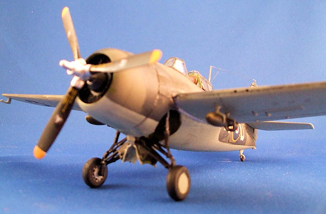
Final assembly
The fuselage, wings and tail surfaces were all
painted and decaled separately to be brought together almost at the end of the
project. Be warned that the fuselage internals interfere with the mounting tabs
on the wings. I left the tabs alone but removed enough of the offending
bulkheads to allow a reasonable fit – filler will be required. 007 wires
provided the long wire antenna, the VHF radio antenna on the fuselage spine, and
the ZB under-fuselage homing antenna. I used the drop tank racks for the bombs
(not sure this is accurate, but have not found any photos of other bomb racks,
if there were any.)
Painting
 Interior – Grumman Wildcats used a variety of
colors (Bronze Green, light gray among others). Eastern followed USN directives
of the era, which had been sort of standardized in the 1943 era as Interior
Green. That’s my interpretation at any rate. Most seem to agree and photos seem
to confirm that the complex landing gear strutery was black on in lower sections
and light gray above. I did the other visible struts in the gear bay with MM
Acryl Interior Green. The visible oil tank is in Pactra yellow per directive,
and the bicycle chains for gear operation are done with Floquil gunmetal.
Interior – Grumman Wildcats used a variety of
colors (Bronze Green, light gray among others). Eastern followed USN directives
of the era, which had been sort of standardized in the 1943 era as Interior
Green. That’s my interpretation at any rate. Most seem to agree and photos seem
to confirm that the complex landing gear strutery was black on in lower sections
and light gray above. I did the other visible struts in the gear bay with MM
Acryl Interior Green. The visible oil tank is in Pactra yellow per directive,
and the bicycle chains for gear operation are done with Floquil gunmetal.
Exterior – Most of the FAA marking flights of
fancy for naval lend-lease aircraft had settled down by this time, and certainly
for Eastern. Thus for my Mk VI,
Gunze
Extra
Dark
Sea
Grey, MM Dark Slate Grey and MM Sky. All these MM paints are enamels.
Markings
FAA 853 Squadron operated at the very end of the
war in anti-shipping strikes from HMS Queen. The national insignia consisted of
Type C Roundels on both surfaces of the wing (the upper
‘C’wing roundel was a very late war change from Type B). Fuselage
roundels were Type C1, with the narrow yellow surround. The fin flash and Type C
roundels are from Aeromaster Sheet 48016 (Grumman Martlets). The wing roundels
are from Micro Decals Sheet 72-7 (‘Great
Britain WW II’) purchased about 1970. The codes
were done in Power Point, printed on white ink-jet paper, outlined with a #11
blade, and painted over with MM sky.
The FM-2 in
1:48
is approaching in excitability that of the Spitfire Mk IX. Sword’s kit was first
on the market and generated lots and lots of adverse comment, thus much was
expected of HobbyBoss’s release. Alas the cognoscenti have been once more
bitterly disappointed, and the after-market crowd has stepped up to assuage
their anger. I am familiar with most of the criticisms (I think) and have
reviewed the online images of the Vector offerings to fix the problems. Using
the Vector pieces as exemplary of the criticisms, we have:
-
A
replacement engine containing the inter-cylinder intakes of the Cyclone
-
A
replacement cowling that is shorter in chord than the kit offering, and does
not contain the prominent intakes of the P&W version.
-
A new
prop that purports to fix hub errors
-
New
fuselage sections replacing the exhaust cut-outs
-
Replacement control surfaces
-
Replacement fin tip extension
 The kit parts are intended to be replaced by
Vector parts per above - my opinion by number.
The kit parts are intended to be replaced by
Vector parts per above - my opinion by number.
-
The
vector engine is good and more finely molded. But once inside the cowl with
the prop installed neither these qualities nor those intakes are noticeable
except to spiders that may visit there. I will install wiring harnesses only
if kit-provided.
-
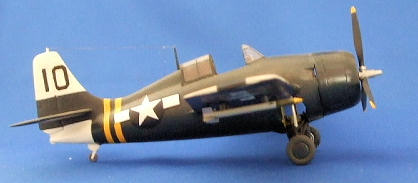
Wright Wildcat cowls are the subjects of much debate. I conclude the Vector
cowl is too short in length per my examination of photo and some (but not
all drawings). I also note the KMC FM-2 conversion cowl (which I have used
on a Mono kit – see photo) is spot-on with the kit cowl.
-
The
Vector hub details are better than the kit hub, and almost as good as the
Monogram and Tamiya hub. But, the issues (if one they exist) are easily
correctible.
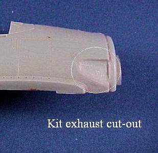
-
The
kit exhausts ‘scallops’ are asymmetrical and too deep in the vertical
dimension. Vector has a cure for this; so do I.
It’s called putty, and there are no shipping charges. But as it
happens, I was able to use the cutout parts from the KMC conversion set.
-
Control Surfaces. Most critics use the Tamiya kit as the gold standard. I
looked at photos, drawings and four kits in this scale – (Mono, Tamiya,
Sword, HB). Apparently there are not enough ‘ribs’ in the HB rudder, a call
impossible to verify with photos because the obvious space anomaly where the
rib may lie is always concealed by the horizontal stab both in photos and
drawings. My built-up
TAM
Wildcat has a red/white early war rudder decal and no ribs are visible under
it – that’s how subtle this is. But, I suspect the rib really should be
there and corrected it but again, without shipping charges.
-
I
cannot figure out what the problem is with the fin tip, and therefore cannot
comment on its alleged solution.
 The kit scales out (wing span and length) to
1:48, and the molding is very good,
particularly the surface detailing. Because it shares most components with the
HB P&W-engined versions, you get a bonus 14-cylinder engine plus two-stage
supercharger intercoolers (Please, please do not ask me which version this is).
Care must be taken with the complex gear, gear bay and cockpit assemblies – I am
reminded of the cockpit challenges of the Accurate Miniatures SB2U kits.Epilogue
The kit scales out (wing span and length) to
1:48, and the molding is very good,
particularly the surface detailing. Because it shares most components with the
HB P&W-engined versions, you get a bonus 14-cylinder engine plus two-stage
supercharger intercoolers (Please, please do not ask me which version this is).
Care must be taken with the complex gear, gear bay and cockpit assemblies – I am
reminded of the cockpit challenges of the Accurate Miniatures SB2U kits.Epilogue
The First and the Last…
December 25, 1940 – Marlet Is
BJ515/BJ525, piloted by LT Carter RN and Sub Lt Parke RNVR shoot down a JU-88
over
Scapa Flow.
First victory for the Wildcat series and first victory by an American aircraft
in British service
August 5, 1945 – LT Beckwith, VC-98,
USS Makin Island, and flying an FM-2 makes the last Wildcat shoot-down of the
war in the
East China Sea.
The victim was a Fran, and ten days later the war ended.
Marlet I
Engine: Wright GR-1820-G295A-2.
HP=1200 at take off.
Armament: Four .50 cal guns/430 rpg as delivered
Empty/Max weights (lbs) – 5236/7065
Max speed – 330 mph
FM-2
Engine: Wright R-1820-56
variant. HP = 1350
Armament: Four .50 cal guns/430 rpg
Empty/Max weights (lbs): 5542/7431
Max Speed: 320 mph
The two airplanes were virtually
identical except for wing folding. What other fighters were still in the
first-line fighter business in August 1945 essentially unchanged from their 1940
configuration? How many other fighters in the first-line fighter business in
August 1945 were even in service in 1940?
-
Balance, T, Sturtivant, R. (1994). The Squadrons of the Fleet Air Arm.
Tonbridge,
Kent,
UK:
Air-Britain.
-
Brown, D. (1974). Carrier Operations in World War II Volume I The Royal
Navy.
Annapolis,
MD:
Naval Institute Press.
-
Dann, R. (1995). F4F Wildcat Walk Around.
Carrollton,
TX:
Squadron/Signal.
-
Dann, R. (2004). F4F Wildcat in action. Aircraft Number 191.
Carrollton,
TX:
Squadron/Signal.
-
Kinzey, B. (1988). F4F Wildcat in detail & scale.
Blue Ridge
Summit,
PA:
Detail & Scale Aviation Publications.
-
Lundstrom, J. (1984). The First Team Pacific Naval Air Combat from
Pearl Harbor
to Midway.
Annapolis,
MD:
Naval Institute Press.
-
Poolman, K. Allied Escort Carriers of World War Two in action.
Annapolis,
MD:
Naval Institute Press.
-
Sturtivant, R. (1990). British Naval Aviation The Fleet Air Arm,
1917-1990.
Annapolis,
MD:
Naval Institute Press.
-
Tillman, B. (1983). The Wildcat in WW II.
Annapolis,
MD:
Nautical & Aviation Publishing Company of
America.
Joe
Lyons
November 2009
If you would like your product reviewed fairly and quickly, please
contact
me or see other details in the
Note to
Contributors.
Back to the Main Page