|
KIT: |
Hobbycraft 1/48 I-16 |
|
KIT # |
1536 |
|
PRICE: |
$15.00 |
|
DECALS: |
Two aircraft |
|
REVIEW & |
Rick Brownlee |
|
NOTES: |
Markings painted on` |
|
HISTORY |
PLEASE TAKE NOTE that I've written a companion article with more about painting
on the markings with an airbrush instead of using decals, entitled "I -16
Revisited". It includes information on mixing paints and using a color wheel.
This article will be coming soon.
The Russian pilots called it "The Fly" and the pilots of the Spanish govenment
forces who flew the I - 16 during the Spanish Civil War called the aircraft the
"Rata" meaning Rat. In March 1933, Nikolai Nikolayevich Polikarpov got
permission to
start work on this new monoplane fighter. Working 18 hour days, his design team
finished the prototype and the fighter made it's first flight on 31 December,
1933. Historians have wondered if Nikolai Polikarpov was thinking of the Gee Bee
Racer. The I - 16 was just 19.5 feet in length; even shorter than Russian
biplanes. The desire for agility was gained from the short length. Although the
Fly looked like a stumpy racer, it was most assuredly a fighter; the first
fighter on the planet to go into service with cantilever monoplane wings and
retractable landing gear. The early versions had an enclosed cockpit. The I - 16
was very tricky to fly and dangerous, to an inexperienced pilot.
 In the Illustrated Encyclopedia of Aircraft Vol. 14, Issue #165 it was
written ‹ about the I - 16 ‹ that the slightest pilot control input caused an
almost violent reaction; airsickness could become a problem! The GOOD result was
that rolls and loops were so fast as to be quite starling. But trying to bring
the guns to bear on another aircraft demanded great skill and concentration.
Polikarpov wanted the Wright Cyclone powerplant for the fighter and it took time
negotiating before an imported Cyclone R-1820-F3 was fitted to the second
prototype. After trials with the Cyclone, the I - 16 was accepted for service.
In the Illustrated Encyclopedia of Aircraft Vol. 14, Issue #165 it was
written ‹ about the I - 16 ‹ that the slightest pilot control input caused an
almost violent reaction; airsickness could become a problem! The GOOD result was
that rolls and loops were so fast as to be quite starling. But trying to bring
the guns to bear on another aircraft demanded great skill and concentration.
Polikarpov wanted the Wright Cyclone powerplant for the fighter and it took time
negotiating before an imported Cyclone R-1820-F3 was fitted to the second
prototype. After trials with the Cyclone, the I - 16 was accepted for service.
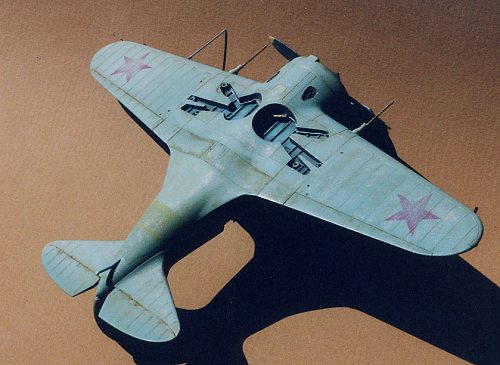
With the I - 16, Type 24B ‹ the last version ‹ maximum speed was 323 m.p.h. at sea level. Armament consisted of two 7.62 mm Shkas machine guns positioned in the upper forward fuselage. Two 20mm ShVak cannons were placed in the wings. RS-82 rockets were positioned on underwing rails. About 20,000 "Rata" fighters were constructed during the course of a little more than ten years, and after their operational debut in 1937 in Spain ‹ mentioned earlier ‹ the fighter remained in front line use until the summer of 1943. The I - 16 was also used in China, Mongolia and Finland.
|
THE KIT |
The kit is really just a "basic" kit and that is what I expected in that price
range. No photoetched, no resin, just the fuselage halves, wings, tail wheels,
only one clear canopy ‹ and decals. The instructions are explosion drawings
without text. Just what I expected however, from building past HC kits. The kit
comes with a fairly decent radial engine, an OK styrene instrument panel ‹ no
instrument panel decal provided ‹ a pilot's seat, a rear cockpit bulkhead and a
cockpit floor.
|
CONSTRUCTION |
 The photo shows the controls
and framing I added to the fuselage halves using sheet styrene, stretched sprue
for lines, tubing, throttle and various knobs. Some of you may not know that if
you take a length of sprue that has been stretched and start slowly pushing it
toward the candle flame, the sprue will melt and ball up back on itself. Whether
you're above the flame or below the flame determines which angle ( or no angle,
if desired) the knob will have. I couldn't find the correct paint for the
interior grey-green (FS 34226 according to the Accurate Miniatures IL-2 Stormovik kit) so I mixed my own interior color in a cleaned out hobby paint
bottle and lid I keep for mixing my own colors. Lacquer thinner is great for
cleaning out paint from bottles. Soak it for several days. (I cover the tin can
I put the lacquer thinner and bottle to be clean out the old paint, with a large
plastic wide mouthed jar to keep the fumes out of the room.) Hopefully in photo
#1 you can see the dark gray short pieces of plastic tubing I glued behind the
exhaust stacks. From the outside of the fuselage halves I drilled out the
exhaust openings (they're solid plastic) and added the plastic tubing cut at the
correct angle behind, so that the exhausts would look more realistic from the
outside. I usually always try to find a way to drill out places that should
look like an opening, i.e. gun barrels. Next, from dry fitting a lot, I realized
that the instrument panel was indicated ‹ quite correctly ‹ very far forward. I
decided to move it aft about one forth of an inch so it would be more visible.
Whenever I add anything scratchbuilt or aftermarket to an interior, I dry fit it
a lot and study it a lot with the two fuselage halves just taped together so I
will know for sure what you can see and what you can't see after you've glued
the fuselage together. Same applies for the techniques for painting interiors.
The photo shows the controls
and framing I added to the fuselage halves using sheet styrene, stretched sprue
for lines, tubing, throttle and various knobs. Some of you may not know that if
you take a length of sprue that has been stretched and start slowly pushing it
toward the candle flame, the sprue will melt and ball up back on itself. Whether
you're above the flame or below the flame determines which angle ( or no angle,
if desired) the knob will have. I couldn't find the correct paint for the
interior grey-green (FS 34226 according to the Accurate Miniatures IL-2 Stormovik kit) so I mixed my own interior color in a cleaned out hobby paint
bottle and lid I keep for mixing my own colors. Lacquer thinner is great for
cleaning out paint from bottles. Soak it for several days. (I cover the tin can
I put the lacquer thinner and bottle to be clean out the old paint, with a large
plastic wide mouthed jar to keep the fumes out of the room.) Hopefully in photo
#1 you can see the dark gray short pieces of plastic tubing I glued behind the
exhaust stacks. From the outside of the fuselage halves I drilled out the
exhaust openings (they're solid plastic) and added the plastic tubing cut at the
correct angle behind, so that the exhausts would look more realistic from the
outside. I usually always try to find a way to drill out places that should
look like an opening, i.e. gun barrels. Next, from dry fitting a lot, I realized
that the instrument panel was indicated ‹ quite correctly ‹ very far forward. I
decided to move it aft about one forth of an inch so it would be more visible.
Whenever I add anything scratchbuilt or aftermarket to an interior, I dry fit it
a lot and study it a lot with the two fuselage halves just taped together so I
will know for sure what you can see and what you can't see after you've glued
the fuselage together. Same applies for the techniques for painting interiors.
In other word it's not what the interior parts looks like in the photo that matters. It is what they look like when you look down into the cockpit of the completed model. Think about that for a second. . .
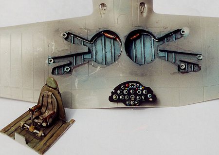 The photo
to the right shows the instrument panel
resting on the lower wing. Hopefully, you can also see the detail in the wheel
wells. I sprayed the instrument panel black Model Master enamel and dry brushed
with white enamel to pick out the instruments. A couple of days later I dabbed Floquil clear gloss on each instrument with a Windsor Newton series 7 pure
The photo
to the right shows the instrument panel
resting on the lower wing. Hopefully, you can also see the detail in the wheel
wells. I sprayed the instrument panel black Model Master enamel and dry brushed
with white enamel to pick out the instruments. A couple of days later I dabbed Floquil clear gloss on each instrument with a Windsor Newton series 7 pure
red sable double zero (00) brush. ( In the companion article I will have more to
say about why a modeler needs the very best quality brushes and the care
required for them.) I scratchbuilt the control column/joy stick. The one from
the kit really was not too close according to my references. The "O" shaped
section at the top of the control column has two little levers
coming up from the control column, for firing the machine guns. I made the two
levers using the same process as with the throttle and other knobs, pushing
stretched sprue toward the candle flame. The "O" shaped top of the control
column was small gauge copper wire twisted around a piece of plastic tubing that
had the correct diameter, then I removed the copper loop, snipped off the excess
wire and superglued it to the control stick. Of course the control stick was
placed on double stick cellophane tape before I started fashioning the levers
and the "O" shaped piece. Working that small, I always fix the main part so it
will remain immobile, on double stick tape. Also, I have three or four lengths
of wooden 2 X 4s. They are about 12 inches in length. I stack them on top of
each other, high enough to be able to support my hand so that I am not working
with either the model piece or my hand in an "unsupported" or shaky position.
This is very important. Especially when I paint canopies with a double
zero (00) brush.
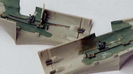
In the wheel wells I used Evergreen strip styrene item # 102 K-3 for the framing supports running from fore to aft. I also added some tiny rectangles and squares of sheet styrene along with copper wire and plastic rod with holes drilled in each end of the plastic rod to receive the copper wire. I like to weather my aircraft models quite a bit and that is another reason why I picked the WWII Russian theatre and the "Fly" in particular. So I painted the wheel wells with tube acrylics and a brush. When dry, I made a wash in a shallow container with water and tube acrylic raw umber and tube acrylic black. I've worked with tube acrylics a lot over the years and feel I have a lot of control in a very small and recessed area like this. However, for weathering the fuselage and wings of the Rata I used a different method to be covered in the painting section, below.
The kit cockpit floor left open areas below the floor level
so I made a new floor from .20 thousandth sheet styrene. We're talking dry fit
city, here. I decided to make a template that fit just right out of card stock
paper first. It was easier to cut the card stock with scissors, to the exact
shape of contour to fit the floor snuggly against the two cockpit side walls .
Trial and error, most assuredly, here. When the paper pattern fit just exactly,
then it was used as a pattern to make the correct shape from sheet styrene. Same
approach for the bulkhead aft of the pilot's seat that I made from sheet
styrene. I made the seat 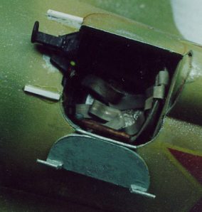 belts from that foil around the top of wine bottles
with corks in them. (the foil isn't lead anymore. We wine drinkers don't want to
die of lead poisoning, now do we. But lead in sheets does also make good seat
belt material.) The wine bottle foil is very
belts from that foil around the top of wine bottles
with corks in them. (the foil isn't lead anymore. We wine drinkers don't want to
die of lead poisoning, now do we. But lead in sheets does also make good seat
belt material.) The wine bottle foil is very
pliable and easy to cut on a piece of auto glass just the right width. (In the
companion article I will say more on using a square of auto glass to assist with
hand made templates for spraying on the national insignias, etc.) I paint the
seat belts right after cutting them. If some paint flakes off while I am bending
the belts into a "candid" position in the pilot's seat, I
just touch them up with a paintbrush. Brown enamel that is in color, harmonious
with the gray-green interior was selected for the belts. There I go again.
Artist first, modeler second.
I decided to open the port side cockpit door somewhat late.
(See: Photos #4 and #5) I'd glued in the side panels and controls already. AND I
glued the fuselage halves together. I should have done it in reverse, naturally.
But I took my time and didn't worry about keeping the portion of the port side
door I was cutting away. I fashioned a new door,
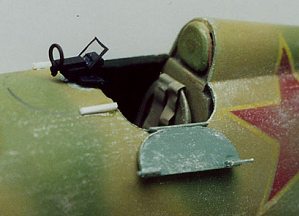 first from card stock paper
that fit just right in the closed position and then used that as a pattern for a
new door cut from a cottage cheese plastic carton because it had the correct
curve. (Of course, the new door was painted and "installed" along with the brass
tubing cannon barrels, stretched sprue pitot tube, kit landing gear, etc. after
the model was almost completely finished.)
first from card stock paper
that fit just right in the closed position and then used that as a pattern for a
new door cut from a cottage cheese plastic carton because it had the correct
curve. (Of course, the new door was painted and "installed" along with the brass
tubing cannon barrels, stretched sprue pitot tube, kit landing gear, etc. after
the model was almost completely finished.)
I scratchbuilt a gun sight using copper wire and Evergreen plastic, item 102 (again) rectangular pieces. Since the kit cockpit canopy was so thick I needed to vacuform a new canopy to gain more room for that little tiny scratchbuilt gun sight. Believe it or not, I have a Mattel vacuform purchased from the Sear's Xmas Toy catalog many years ago. I got a good canopy copy on the first try.
Looking at reference photos in the Squadron Signal book I realized I needed to add .05 thousandth sheet styrene behind the openings in the engine cowl kit part to simulate the louvers or baffles on the inside of the engine cowling. This step improved the realistic look of that 'shortstuff" Rata viewed from the front.
All in all, the fuselage halves went together very nicely with just a little sanding and filling of gaps. Correct alignment of part like the wings and horizontal stabs is very important of course, and in the case of this kit's horizontal stabs, it requires careful attention. For these chores I used tube glue for it's slow drying capability. I checked the alignment a lot in the first 10 minutes. The laws of gravity apply here of course, and the weight of the plastic parts allows them to droop. I kept checking and repositioning them. I don't like masking tape to hold them in place. With the tape on the model it is harder for me to tell if the alignment is correct in the first place. I came back and checked again and again for more than 30 minutes. Obviously I don't glue the fuselage together and the wings together or horizontal stabs on the same day.
I used green stuff and super glue for filler. I rescribed the sanded panel lines with an Xacto-knife and a 6 inch flexible steel ruler with cork backing ‹ from Micro Mart ‹ in areas where the curve isn't too acute. This is a very slow and careful process. The Rata wing root required filler and sanding, then I sprayed a coat of white paint in those areas to check how well I did or didn't do. Then more filler and more sanding till there was no trace of plastic parts coming together. We all know this procedure isn't fun but we also know that it is the correct way to build QUALITY models. But on the other hand, I think a modeler should enjoy building models. It should be fun. If all that sanding and filling isn't fun for you then don't do it. We're not talking about IPMS competition here. That is another story.
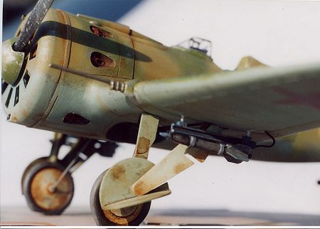
 I cleaned up all the mold marks from the landing gear parts
and substituted .05 thousandth sheet styrene for two sets of the smaller
portions of the gear doors. Each gear door assembly is in 3 pieces. That does
not include the landing gear struts. I painted and weathered the landing gear
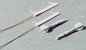
assemblies and flattened the tires; and set them aside. Scratchbuilt RS-82
Rockets added underwing
I cleaned up all the mold marks from the landing gear parts
and substituted .05 thousandth sheet styrene for two sets of the smaller
portions of the gear doors. Each gear door assembly is in 3 pieces. That does
not include the landing gear struts. I painted and weathered the landing gear
assemblies and flattened the tires; and set them aside. Scratchbuilt RS-82
Rockets added underwing
From looking at the color renderings on the back cover of
the Squadron Signal book I saw the RS-82 rockets and rocket launcher rails.
Whooooo! cool man! So I decided to scratchbuild them. Since I had the Accurate Miniatures 1/48th IL-2 Stormovik kit I looked at
the RS-82 rocket parts from that kit. Scale wise they were too long for the I -
16 wing chord but they helped me with proportions. I used
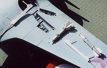 .05 thousandth sheet
styrene for the rocket's aft fins. I used tube styrene for the body of the
rockets and put putty on the front end so I could sand it down to a rounded
shape. I drilled holes in smaller diameter plastic rod and glued that very short
piece into the aft end of the rocket body. The two bands around the rocket body
were made from the wine bottle material I made the seat belts from and glued
with cyno or super glue. First however, the rocket body were fastened with
double stick cellophane tape to keep them from moving and have both hands free.
The glue was applied in very tiny amounts in the critical areas with the point
of a sharpened tooth pick.
.05 thousandth sheet
styrene for the rocket's aft fins. I used tube styrene for the body of the
rockets and put putty on the front end so I could sand it down to a rounded
shape. I drilled holes in smaller diameter plastic rod and glued that very short
piece into the aft end of the rocket body. The two bands around the rocket body
were made from the wine bottle material I made the seat belts from and glued
with cyno or super glue. First however, the rocket body were fastened with
double stick cellophane tape to keep them from moving and have both hands free.
The glue was applied in very tiny amounts in the critical areas with the point
of a sharpened tooth pick.
Next, I applied the tail skid straight from the kit. And now it was time to crank up the airgun. Hopefully, all those years of retouching newspaper photographs would come in handy.
|
PAINT & MARKINGS |
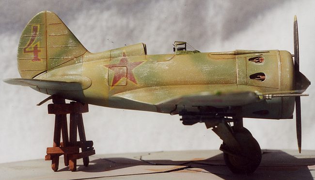
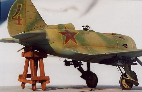
I was out of the hobby for quite a few years and didn't get in on the bottled acrylic "bandwagon". Acrylics are super but I like enamels and love the prices for say, Humbrol enamels as compared to the price of the "new" ACRYLICS. So with the exception of the tube acrylic paints I used to paint the wheel wells and the cockpit floor, I used enamel of Humbrol, Model Master and the old Testors little bottles of Rust, Copper, and Brass. I used the I - 16 paint scheme from page 26 of the Squadron/Signal book on the Rata. I wanted to show a lot of weathering and wear, fading and chipping of paint so I picked the scheme at the bottom of page 26 with the big Red 4 on the vertical tail, the yellow band around the aft end of the fuselage, and the two tone camouflage scheme. We're talkin' bad! Another great scheme is the one on page 27, second up from the bottom in the Royal Rumanian Air Force scheme. Boo Yeah! It's too much!
Actually, the I - 16 has a lot of really eyecatching schemes and they're crying for a "this baby's been thru Hell" weathering approach. OK, I know lots of modelers don't agree with this opinion. That is OK. Again, we can agree to disagree. Some modelers feel that the more "artistic" paint techniques are not authentic or accurate. I understand what they mean. I'm not a crusader. But I just disagree and have seen the photos that in my view, back me up in reference to paint chipping and fading. But really, it's whatever you are comfortable with that is important.
 First I sprayed the undersides and used the
low tack blue masking tape to mask off the undersides from the curve that goes
into the leading edge of the upper wing. I cut the tape on a piece of auto glass
I got free from an auto glass installation business. Also, using double stick
tape, the auto glass is good for cutting photo etched parts as well. I couldn't
find a bottled color that would have the correct look for a faded paint so I
mixed my own in an empty hobby paint bottle and marked it to keep straight what
surface the paint was for. (Sometimes weeks go by without working on a kit.) To
make the underside "light-blue" I started with white enamel, then added azure
blue and then a touch of forest green. I sprayed it on a spare piece of plastic,
allowed it to dry, and checked to see how close to the color I wanted it was,
and proceeded from there.
First I sprayed the undersides and used the
low tack blue masking tape to mask off the undersides from the curve that goes
into the leading edge of the upper wing. I cut the tape on a piece of auto glass
I got free from an auto glass installation business. Also, using double stick
tape, the auto glass is good for cutting photo etched parts as well. I couldn't
find a bottled color that would have the correct look for a faded paint so I
mixed my own in an empty hobby paint bottle and marked it to keep straight what
surface the paint was for. (Sometimes weeks go by without working on a kit.) To
make the underside "light-blue" I started with white enamel, then added azure
blue and then a touch of forest green. I sprayed it on a spare piece of plastic,
allowed it to dry, and checked to see how close to the color I wanted it was,
and proceeded from there.
Next, I cut small pieces of masking tape and stuck them together to covered the cockpit opening. I masked and sprayed the lighter color of the two camouflage colors on all the upper surfaces. Then I looked at my reference and sprayed the outline of where the darker green would go. Again, I had premixed my own "faded" brown and faded green colors in empty hobby paint bottles that were marked. I have a Thayer and Chandler ( that company was purchased by Badger some years ago. Pitty; it's not near as good a brush) double action airbrush and it will make very thin lines. Perhaps I should mention here that I use a CO2 cylinder and usually spray at 22 psi.
Then I masked off the area where the faded yellow band on the aft portion of the fuselage would go. I shot the light yellow to simulate faded paint) on the model and took off the tape. Oops. Too bright. So I repainted the faded colors of the two tone camouflage over the yellow band, once again. Then I masked off the yellow band area and tried it again with the light yellow only with a lot less spraying. This time I got the results I was after. You have to look close in the photo to see the faded yellow band.
Then I started the process of making my own markings instead of using decals. I will go into a lot more detail for those who are interested in this approach in the companion article. But I will say here that since I'm painting a model to look weathered with faded paint, da. . . well, then the markings on the aircraft would have to look the same. So then decals can't be used. They're a "straight out of the factory bright" kind of finish. So then that means I have to spray on my own markings and just give them a light spray. And that is what I did for the numeral "4" on the tail and the national insignias of the Red stars on the wings and the Red Star with yellow surround for the fuselage.
 After this was completed ‹ it took me three tries to get the
port side national insignia on the fuselage correctly "faded" ‹ I was then ready
to seal the paint scheme. Then I sprayed a mixture of three parts mineral
spirits and two parts flat varnish. Now modelers, I mean flat varnish, not satin
varnish. It took me a while to find it in a Kansas City hardware store. That
mixture sprayed from my airbrush seals the painted model against the weathering
wash that will come next. After spraying the model with the mineral spirits and
flat varnish mixture I waited 48 hours. Then I used a wash of tube oil paints
and mineral spirits on the model. Turpentine will work with oil paints just as
well but the smell is more pronounced than with mineral spirits. I have a
dimpled palette in which I mixed the tube oil and the mineral spirits to make
the "wash" I desire. I put out dabs of tube oil paints: burnt sienna, raw umber,
black and white. I use a large red sable brush to spread the oil wash over the
models surfaces. However, first I get out my old hull of the Monogram USS Halsey
kit to experiment on. I don't like surprises. You don't want surprises, either.
So I find out what works for sure on the old Halsey hull before aiming at the
Rata. Ladies and gentlemen, I spent a total of 120 hours in this kit! I didn't
want to mess it all up with a messed up wash. After I was satisfied with the
correct color of the wash on the old Halsey hull, I started to apply it to the
model with the large paint brush.
After this was completed ‹ it took me three tries to get the
port side national insignia on the fuselage correctly "faded" ‹ I was then ready
to seal the paint scheme. Then I sprayed a mixture of three parts mineral
spirits and two parts flat varnish. Now modelers, I mean flat varnish, not satin
varnish. It took me a while to find it in a Kansas City hardware store. That
mixture sprayed from my airbrush seals the painted model against the weathering
wash that will come next. After spraying the model with the mineral spirits and
flat varnish mixture I waited 48 hours. Then I used a wash of tube oil paints
and mineral spirits on the model. Turpentine will work with oil paints just as
well but the smell is more pronounced than with mineral spirits. I have a
dimpled palette in which I mixed the tube oil and the mineral spirits to make
the "wash" I desire. I put out dabs of tube oil paints: burnt sienna, raw umber,
black and white. I use a large red sable brush to spread the oil wash over the
models surfaces. However, first I get out my old hull of the Monogram USS Halsey
kit to experiment on. I don't like surprises. You don't want surprises, either.
So I find out what works for sure on the old Halsey hull before aiming at the
Rata. Ladies and gentlemen, I spent a total of 120 hours in this kit! I didn't
want to mess it all up with a messed up wash. After I was satisfied with the
correct color of the wash on the old Halsey hull, I started to apply it to the
model with the large paint brush.
One of the beauties of the oil washes is that if you don't like the results you can use mineral spirits on a clean rag to wipe the wash off and start over again. When this "weathering wash" was finished I drybrushed Model Master flat aluminum sparingly using the Windsor Newton series 7 double zero (00) brush to simulate chipping and wear in areas where the crews would walk on the wing, on the propeller, etc.
|
FINAL ASSEMBLY |
After the painting was completed I weathered and installed the prop. I had
previously drilled a center hole in the engine to take a metal tube glued into
the center hole of the engine. Then I glued a small diameter brass tube of
about an inch and a half in length (that would fit inside the metal tube
previously glued into the engine) into a drilled hole into the center of the
back of the prop hub. After all construction was completed I slid the prop's
brass rod down into the metal tubing and then the prop would really spin easily.
Next I installed the landing gear. It was a major nightmare. Hello! Are you
listening? A major nightmare! A real test of patients. But if you look at the
photos of the real aircraft you see that the landing gear is very complex. If
you build this kit take your time and make sure you understand just what goes
where with the landing gear, AND at what angle. I took very thin strips of
masking take and taped all the l.g. parts together at the correct angles into
the wheel wells ‹ learned from trial and error and no, the instruction don't
help much here ‹ to find out; to understand just how this nightmare had to go
together before I ever picked up the tube of glue. Please do the same. Don't
rush this part of construction.
|
CONCLUSIONS |
For the most part the construction of the kit and fit of parts is quite good. And I would recommend this kit to any experienced modeler who will have patience with the installation of the landing gear; build it straight from the box and the landing gear is the only tricky part. (See: Photo #14) However, as my photos of the landing gear hopefully show, there should be a piece of sprue or steel wire (I used sprue) coming out of the inside of each wheel hub that goes up into the wheel wells. The Squadron Signal books shows this and the correct angle quite clearly in the line drawings. Although I put a lot of thinking into the installation of the landing gear, I forgot to drill the holes in the wheel hubs to receive the sprue. I had to very carefully drill these holes in the wheel hubs and up in the wheel wells to receive the lengths of stretched sprue AFTER the landing gear and gear doors were installed. Luckily I didn't break anything but that isn't the way it should be done.
I also recommend the Hobbycraft kit to any modeler who wants to try a more "esoteric" aircraft kit, and to march to the beat of a different and more UNIQUE "drummer", who would like to build a representation of a great little fighter, that in the hands of an expert pilot held it own against the Bf 109s. Remember the Polikarpov I - 16 flew at a time when the Russian Air Force ‹ waiting for the LAGG and YAK fighters to come ‹ had little else to halt the Luftwaffe onslaught. She was a valiant little Fly in the hands of some very brave airmen. And the way I chose to salute these airmen was to construct this kit.
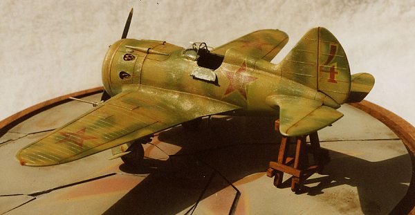
Does this stubby stalwart need a base?
I noticed several reference photos that showed the Rata with the tail
being held up on either a wooden or metal frame during maintenance. Should I
say "candid"? Oh yeah. The kind of different stance I was looking for! Haven't
seen many models displayed that way. My wooden stand was made
from popsicle sticks sawed in halves or quarters lengthwise and painted with oil
paints. Hey, those "craft sticks" are very strong but easy to saw or drills
holes in. I put two steel pins ‹ made from cutting the heads off of straight
pins ‹ up into two of the legs of the "pop stand". Then I countersunk two short
pieces of metal tubing down into the base so that I could push the maintenance
"stand" pins down into the holes in the base to hold it still. When in transit,
however, I put the little stand in a small box for safe keeping.
My exit line is that in the companion article I will discuss my
thinking on the base I designed for my I - 16 (a Red star and hammer and sickle
on cracked cement surface) and what to consider, besides the model, in the total
concept of a "presentation"; more details about the color wheel and how to
properly mix the colors you want using primary, secondary and complimentary
colors quite easily; why you should use the best possible pure red sable brushes
available, what they are and how to properly care for them; AND more detail
about how and why I make my own aircraft markings in 1/48th scale.
|
REFERENCES |
1. Profile Publication number 122, The Polikarpov I - 16
2. Illustrated Encyclopedia of Aircraft Vol. 14, Issue #165 mentioned above.
3. Squadron/Signal #162 Polikarpov Fighters in action, Part II w/ some bitchin' color schemes.
4. Line drawings of the instrument panel and port and starboard
cockpit panels from Pavel Krapicka in Prague, Czechoslovakia sent in the 1970s.
Anyone that will pay postage/handling is welcome to copies from me. Email:
rbrownlee@kc.rr.com
Here is the second part of Rick's article
If you would like your product reviewed fairly and quickly by a site that averages thousands of visits a day, please contact me or see other details in the Note to Contributors.