Special Hobby 1/48 IMAM Ro.44
| KIT #: | |
| PRICE: | $ |
| DECALS: | Two options |
| REVIEWER: | Michael Rohde |
| NOTES: | Short run with photo etch and resin parts |
| HISTORY |
The Ro 44 was a single seat version of it's stablemate, the twin seater Ro 43.
The Ro 44 prototype first flew in
October 1936 and the major difference in overall design to the Ro 43 was a
slightly different upper fuselage and heavier armament consisting of two Breda Safat 12.7 mm calibre
 machine guns.
Both the Ro 43 and 44 were the Italian Navy's standard ship based catapult launched float plane and some 40 machines out of a total of about 140 planes were built in the Ro 44 single seat configuration.
Ro 44 fighters were used for patrol and armed reconnaissance work serving mainly in the Aegan Sea against Allied shipping. They also operated as shore based defence in day and night intercept missions against British bombers.
Being rapidly outclassed by more advanced Allied aircraft , the Ro 44 float plane fighters were finally withdrawn to serve as training aircraft only.
| THE KIT |
 This is another one of Special
Hobby,s multi media kits consisting of 4 Sprues with 46 parts in grey plastic,
one clear sprue for the windshield fifteen resin parts and a sheet of 24 photo
etched parts. Overall details like panel lines
and fabric surfaces are subtle.
This is another one of Special
Hobby,s multi media kits consisting of 4 Sprues with 46 parts in grey plastic,
one clear sprue for the windshield fifteen resin parts and a sheet of 24 photo
etched parts. Overall details like panel lines
and fabric surfaces are subtle.
Decals are provided for two versions and are of superb quality ( made by Cartograf) The instructions provided are adequate .
Care has to be taken during assembly since no locator pins or such are given and careful dry fitting and alignment of parts are recommended.
| CONSTRUCTION |
After separation of all respective parts from their sprues and removing all flash I attached the internal steel tube framing to the fuselage keel surfaces. Then I assembled the cockpit floor together with the controls.
The support frame for the seat is only held into place by two little pins . So I decided to fashion another support to go under the seat to help me align the seat with the fuselage attachment point and the cockpit floor. This support plate can be seen right behind the control column.
 After painting the seat I carefully
attached the harnesses. Despite the fact that the radio unit will disappear
forever from sight after closing up the fuselage I decided to paint and
highlight all the nice detail given with this resin part.( see photo)
After painting the seat I carefully
attached the harnesses. Despite the fact that the radio unit will disappear
forever from sight after closing up the fuselage I decided to paint and
highlight all the nice detail given with this resin part.( see photo)
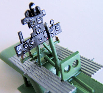
The instrument panel was painted black and I let the paint dry completely before I high lighted the dials using a very thin paint brush and let that dry off as well. The I sealed the dials with drops of Tamiya clear and that in return makes it look like the glass covers on the flight instruments.
Next I prepared all the resin parts and photo etch to be attached to the cockpit walls and after glueing these bits into place I carefully painted these details. The machine guns were pre painted before attaching these to the platform.
The engine in the kit did need some additional detail. These being the pushrod tubes the distributor ring for the ignition leads and the leads themselves. I used the stretched sprue technique to make the pushrods and used Evergreen rod to form the distributor ring with their respective attachment points for the ignition leads. The leads are made of thin copper wire. Otherwise we are given a nice resin circular oil cooler supported by a photo etch frame. The exhaust system is made of resin as well and does fit nicely onto the carrier plate with the carburettor intake tubes.
Closing the fuselage and attaching tailplane and wings.
All cockpit internals painted and assembled I carefully slotted these into place , holding them with small strips of masking tape and dry fitted both fuselage halfes to make sure that there were no gaps which would require adjustment. That sorted I carefully glued the cockpit and seat assembly into place using CA glue. Then I joined the fuselage shells.
 Upper and lower wings ( 2 parts
each) were assembled ,filler was used at the seams and carefully sanded and
finished. I drilled out holes for the navigation lights at the upper wing tips
and made clear plastic rods out of stretched sprue, rounded the tips and glued
these tiny stubs into place. I did the same with the nav. Light on top of the
fin pointing aft. Since the aileron control linkages were not provoded in the
kit , I had to fashion these out of Evergreen sheet and 0.2 mm rod.
Upper and lower wings ( 2 parts
each) were assembled ,filler was used at the seams and carefully sanded and
finished. I drilled out holes for the navigation lights at the upper wing tips
and made clear plastic rods out of stretched sprue, rounded the tips and glued
these tiny stubs into place. I did the same with the nav. Light on top of the
fin pointing aft. Since the aileron control linkages were not provoded in the
kit , I had to fashion these out of Evergreen sheet and 0.2 mm rod.
The horizontal tail planes needed some finishing around the edges and the locating pins and interface with the keel surface needed some trimming to align these with as little gap as possible . This helped to keep filling and sanding to a minimum.
Wings and tail plane were glued into place. Overall fit of the wings was quite good and required little correction. In the meantime I made sure that the windscreen had a snug fit on the top of the fuselage. That was straight forward and done quickly. Then I prepped all the supporting struts , made sure that these were in proper angular alignment with as little gap as possible and glued the tail plane,lower wing/ fuselage supports into place.
Having studied the location of all the attachment points for the bracing wires by looking at photos on the net and drawing a little diagram using the drawings on page 8 of the instruction sheet ( step 18) I then drilled all the holes for the bracing wires were needed using a 0.10 mm dental drill bit. Having done that I attached the outer wing and inner ( upper )struts and let everything sit and cure before proceeding.
Central and outrigger floats, engine cowling assembly.
 First of all I prepared all the
float support struts and then assembled the center float and outrigger float
bodies. The overall fit was ( again ) quite good and needed little correction
using filler and a bit of sanding and finishing. Quite a number of photo etch
parts are provided : I. e. rudder ( 2 pcs) , mooring rings fore and aft as well
as on port and starboard( 6 pcs) Filler cap lock handles for the fuel tanks.( 7
pcs). All the bits were glued into place using CA glue.
First of all I prepared all the
float support struts and then assembled the center float and outrigger float
bodies. The overall fit was ( again ) quite good and needed little correction
using filler and a bit of sanding and finishing. Quite a number of photo etch
parts are provided : I. e. rudder ( 2 pcs) , mooring rings fore and aft as well
as on port and starboard( 6 pcs) Filler cap lock handles for the fuel tanks.( 7
pcs). All the bits were glued into place using CA glue.
One has to be careful to follow the instructions and use the right support struts by the numbering provided on the parts diagram. The reason for that is that these ( esp the outrigger struts) are of different length and in order to get the alignment of the floats right there is no other way to get it right.
The center float supports are easier to deal with. It became tricky when I had to get the alignment fore aft right. That needed a bit of re drilling the holes for the rear struts to get that right. I also opened up the front attachment holes to give myself a bit of wriggle space. The extra gap was easily filled with CA glue after the center float was in place.
 Important to mention is that before
I started I made sure that all the attachment points for the center float
bracing wires were drilled out. ( There are 8 holes to take care of)
Important to mention is that before
I started I made sure that all the attachment points for the center float
bracing wires were drilled out. ( There are 8 holes to take care of)
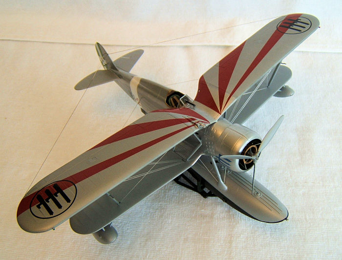
Re the engine cowling: I did not follow the instructions ( which says you have to glue the engine into one half, then glue the other half into place)but glued the halfes together first ,filled the seams and carefully finished these. Panel lines needed re-engraving.
I made sure that the engine assembly slotted into place nicely. Since it was a very tight fit and there was a risk to split the seams again I carefully reduced the outer rim of the engine support plate bit by bit until everything slotted into place in such a way that I also could easily retrieve the engine and paint the inside of the cowling in interior green. Also important was to wait with the circular oil cooler attachment and the 3 cowling supports until the engine was in place.Otherwise there would have been a good chance to break these fragile bits while fitting the engine into the cowling. The exhaust system was glued on after the cowling had been painted and the engine was glued into place.
| COLORS & MARKINGS |
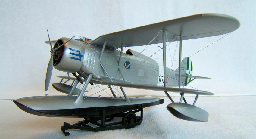
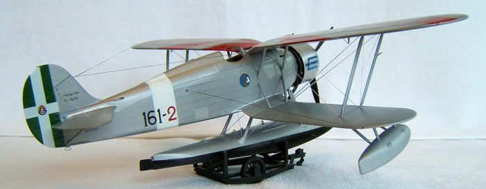
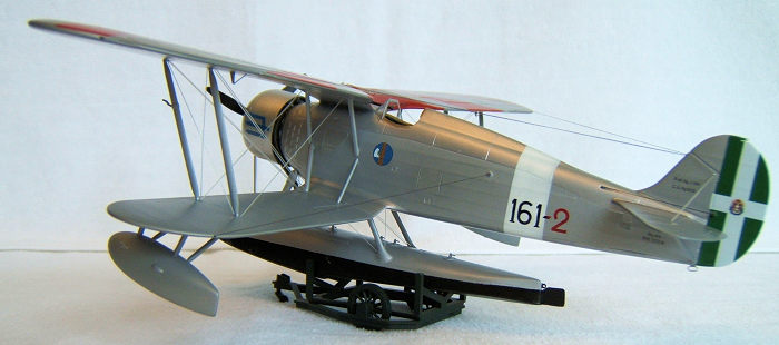
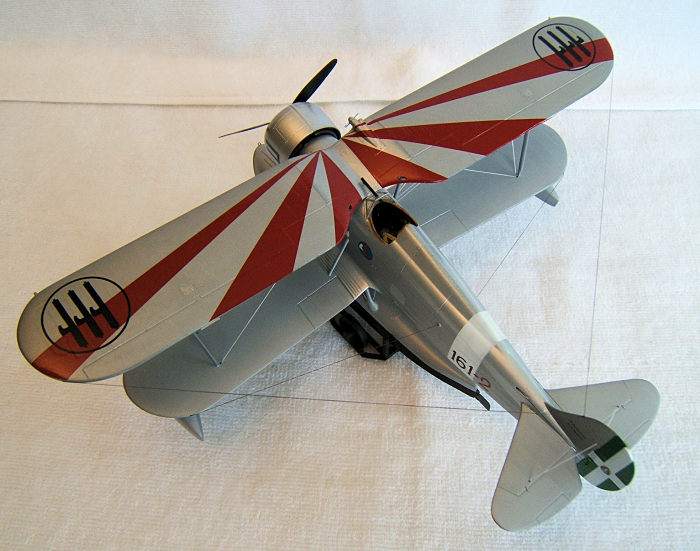
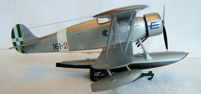
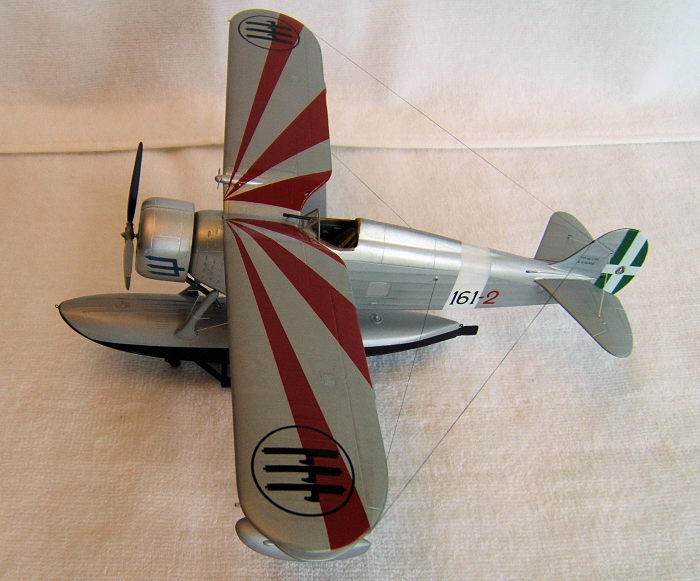
The paint scheme is as simple as it can get. The instruction tell us to paint the bottom of the floats in black and the rest of the aircraft in aluminium silver. Depending on which unit markings we want to use, there is an additional fuselage band in white and a rudder painted in italian green to add to the scheme. Which is what I choose.
To make the appearance of the aircraft a bit more interesting, I decided to use Humbrol 11 chrome silver on all the panel work and Tamiya XF 16 flat aluminium on all fabric surfaces. The undersides of the floats I painted with Tamiya XF 1 flat black. Prior to decalling I gave the lot a coating with Tamiya gloss clear.
 Stage 5.: Rigging.
Using a compass to determine the length of the rigging wires I cut and prepared the entire set of rigging wires( 27 pieces for the rigging , 3 for the antenna wires and two for the rudder control ) and proceeded to glue these into place with CA glue with the help of a small probe which I made of stretched plastic sprue.The tip of the sprue is cut on an angle in such a way that it will pick up a small drop of glue sufficient to fill these tiny holes without overflowing.
Now was the time to fit the pre fitted and pre painted wind screen and the gun sight into place. All went well and I could continue to apply the decals. I have choosen the markings of 161 Squadraligia Autonoma Caccia Marittima stationed at Rhodos / Greece in 1941. The decals are very good indeed and these went on like a dream.( using micro sol decal solution.) After the decals had set I gave these a thin sealing coat of Tamiya gloss clear. ( not forgetting to mask off the windscreen beforehand to avoid overspray)
| CONCLUSIONS |
This kit gives us a very nice base to create an interesting example of Italian Aviation History. As with all Special Hobby kits, a bit of extra work is required but the additional work is well rewarded with a nice end result. I can recommend this kit to all these modellers out there who are interested in float planes in general.
Michael Rohde
16 November 2017 Copyright ModelingMadness.com If you would like your product reviewed fairly and fairly quickly, please
contact
the editor or see other details in the
Note to
Contributors. Back to the Main Page
Back to the Review
Index Page
Back to the Previews Index Page