| KIT #: | 09588 |
| PRICE: | €29.95 |
| DECALS: | Two JG 54 options |
| REVIEWER: | Sjon van der Heiden |
| NOTES: | Verlinden Super Update Me-109G-2 no 1302 used |
| HISTORY |
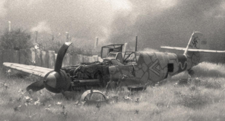
 ppenkommandeur Maj. L. Schlemiel (Stab III./JG 13). As
nighttime turned
into day, he was forced to attempt a belly landing, because
something happened to him while he was flying home. He severely damaged the
portside wing when the plane finally came to a stop at the end of a muddy
field, only 24 hours from Tuzla. Several days later it was partly dismantled
and transported back to base. Here is where the photograph was taken. As
grainy as that picture is, it still gave me a pretty good idea of what it
must have looked like.
ppenkommandeur Maj. L. Schlemiel (Stab III./JG 13). As
nighttime turned
into day, he was forced to attempt a belly landing, because
something happened to him while he was flying home. He severely damaged the
portside wing when the plane finally came to a stop at the end of a muddy
field, only 24 hours from Tuzla. Several days later it was partly dismantled
and transported back to base. Here is where the photograph was taken. As
grainy as that picture is, it still gave me a pretty good idea of what it
must have looked like.| THE KIT |
 the G or even the F
version. Some of these parts could have been omitted all together as both
the entire E and L sprue are labelled not for use (machinegun cowling and
main wheels). Kudos to Hasegawa for including these parts all the same. The
gun cowling and main wheels for the G2 are provided as resin parts. The
quality of these and the quality of the styrene mouldings
are top rank. The detailing is superb, there is no flash and there will be
no visible ejector pin marks once the model is completed. There are very
shallow sinkholes on both flaps but I did nothing to try to correct this and
once painted with matt paint they are impossible to discern. The interior is
a bit Spartan but I suppose it’ll be acceptable to most. No pilot is
included.
the G or even the F
version. Some of these parts could have been omitted all together as both
the entire E and L sprue are labelled not for use (machinegun cowling and
main wheels). Kudos to Hasegawa for including these parts all the same. The
gun cowling and main wheels for the G2 are provided as resin parts. The
quality of these and the quality of the styrene mouldings
are top rank. The detailing is superb, there is no flash and there will be
no visible ejector pin marks once the model is completed. There are very
shallow sinkholes on both flaps but I did nothing to try to correct this and
once painted with matt paint they are impossible to discern. The interior is
a bit Spartan but I suppose it’ll be acceptable to most. No pilot is
included.| CONSTRUCTION |
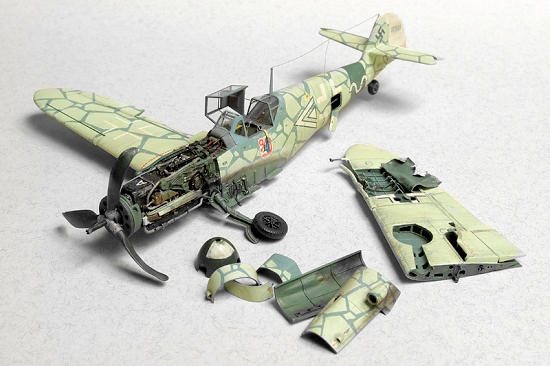
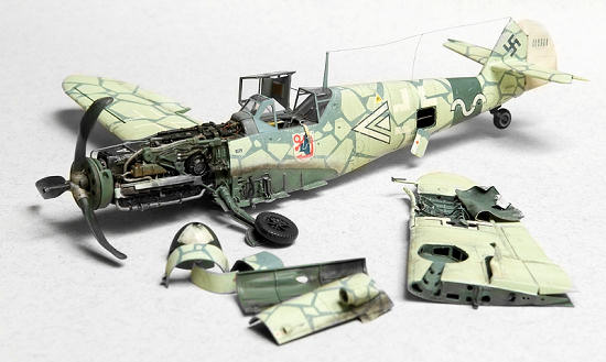
 Construction starts with… the portside wing! Since this was going to be my
first attempt at super detailing anything, I figured I had better see if I
was any good at it. So, out came the razor saw and of went the wing. I also
removed the wheel well, and opened the holes in the leg trough. Installing
the photo etched walls of the wheel well was tricky as it involves a lot of
bending and curving. Getting the edges flush with the underside of the wing
is another time consuming chore, but since the insert is made of brass, it’s
easy to work with. The detail this insert provides is impressive. Too bad
though it doesn’t even remotely resemble the outlay of a G2 wheel well wall
(or any other version I know of). In total I’ve spent countless hours
searching for reference material on the 109, but I figured Verlinden would
have done his homework properly and never bothered to search for any
reference for the wheel well. Unfortunately, this turned out to be
Verlinden's first mistake of many. I could have hidden most of it by using
the photo etched canvas cover, but then I would be practically back to
square one detail-wise, so I’ll rest with it in the knowledge most won’t
notice.
Construction starts with… the portside wing! Since this was going to be my
first attempt at super detailing anything, I figured I had better see if I
was any good at it. So, out came the razor saw and of went the wing. I also
removed the wheel well, and opened the holes in the leg trough. Installing
the photo etched walls of the wheel well was tricky as it involves a lot of
bending and curving. Getting the edges flush with the underside of the wing
is another time consuming chore, but since the insert is made of brass, it’s
easy to work with. The detail this insert provides is impressive. Too bad
though it doesn’t even remotely resemble the outlay of a G2 wheel well wall
(or any other version I know of). In total I’ve spent countless hours
searching for reference material on the 109, but I figured Verlinden would
have done his homework properly and never bothered to search for any
reference for the wheel well. Unfortunately, this turned out to be
Verlinden's first mistake of many. I could have hidden most of it by using
the photo etched canvas cover, but then I would be practically back to
square one detail-wise, so I’ll rest with it in the knowledge most won’t
notice.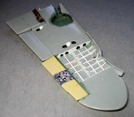 After this I removed the lower wing panel to show of the rib structure in
there. I duplicated the panel in wine bottle foil and bended it backwards,
as if the panel had been ripped open during the belly landing. The internal
bracing and several bulkheads had to be made from scratch by using Evergreen
sheet of various thicknesses. All the lightening holes were made with a no.
11 blade gently turning around till the desired diameter is acquired. The
hinges and eyelets were also made out of Evergreen sheet. First I made a
hole and then I would cut the shape around it. I opened up some of the
inspection hatches and made some covers. I suppose these hatches actually
open up to something very important to inspect, but since I was unable to
find out what was supposed to be behind them, they open up to a carefully
black painted void. A lot of time went into thinning down the plastic around
all the areas I opened up.
After this I removed the lower wing panel to show of the rib structure in
there. I duplicated the panel in wine bottle foil and bended it backwards,
as if the panel had been ripped open during the belly landing. The internal
bracing and several bulkheads had to be made from scratch by using Evergreen
sheet of various thicknesses. All the lightening holes were made with a no.
11 blade gently turning around till the desired diameter is acquired. The
hinges and eyelets were also made out of Evergreen sheet. First I made a
hole and then I would cut the shape around it. I opened up some of the
inspection hatches and made some covers. I suppose these hatches actually
open up to something very important to inspect, but since I was unable to
find out what was supposed to be behind them, they open up to a carefully
black painted void. A lot of time went into thinning down the plastic around
all the areas I opened up.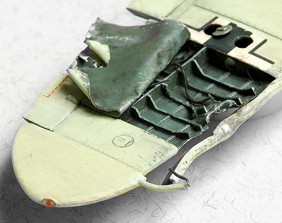 Oh well,
I’ll make sure to bend the wine foil panel in such a way it will hide most
of it. The edges of the slat were thinned down and then I twisted it with
the help of a candle flame.
Oh well,
I’ll make sure to bend the wine foil panel in such a way it will hide most
of it. The edges of the slat were thinned down and then I twisted it with
the help of a candle flame.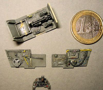
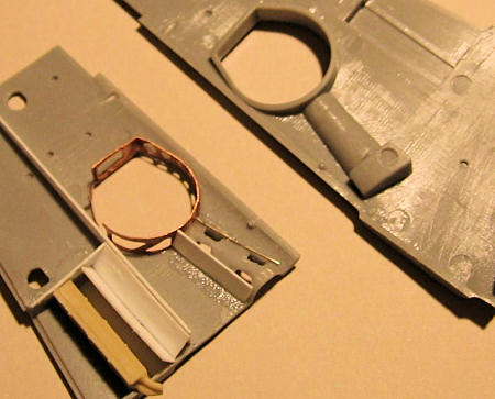
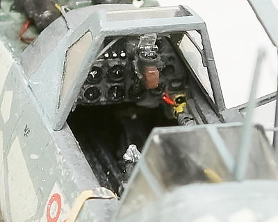 em in their respective bezels. That would have looked so
much smarter. Contrary to what the instructions make you believe, the Revi
C12 should not be assembled directly onto the
instrument panel. So I used a piece of plastic to put a little distance
between the panel and the gun sight. And while I was at it, I also added two
electrical cables to connect it to the instrument panel.
Impossible to see once the windscreen is in place, but at least I know it’s
there. When the time came to put the cockpit in between the fuselage halves
it all fitted perfectly.
em in their respective bezels. That would have looked so
much smarter. Contrary to what the instructions make you believe, the Revi
C12 should not be assembled directly onto the
instrument panel. So I used a piece of plastic to put a little distance
between the panel and the gun sight. And while I was at it, I also added two
electrical cables to connect it to the instrument panel.
Impossible to see once the windscreen is in place, but at least I know it’s
there. When the time came to put the cockpit in between the fuselage halves
it all fitted perfectly.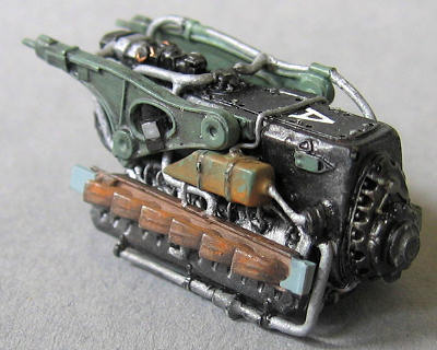 bing is pretty hard work as they crisscross and interconnect with one
another. You really have to figure out yourself what will be the best order
into which to construct everything. By now things are beginning to go awry.
The instructions will have you put the oil coolant header tanks way to far
to the front of the engine. This is due to the fact the tanks are some 3mm
to long. This should be taken off from the rear end of the tanks, and the
middle of the tanks should be directly under the engine suspension points.
If you do not get this right, the engine bearers will misalign and as a
result, so will the entire engine. Now there should be 2 struts supporting
the engine bearers but there are not. Nor are these mentioned in the
instructions. They are easily scratch build, but not as easily installed.
They interfere with the exhaust manifold. They shouldn’t (and in reality
they don’t), but they do here. There is just no other way to fix this than
to take some material from the back of the exhaust stacks. Needless to say I
discovered this after gluing the exhausts in place. So off they came, and
back on they went. After successfully reattaching them, I noticed they flare
up, instead of sticking out at a 90º angle. I just didn’t feel like getting
them off once more to fix this problem and took my chances at nobody taking
notice.
bing is pretty hard work as they crisscross and interconnect with one
another. You really have to figure out yourself what will be the best order
into which to construct everything. By now things are beginning to go awry.
The instructions will have you put the oil coolant header tanks way to far
to the front of the engine. This is due to the fact the tanks are some 3mm
to long. This should be taken off from the rear end of the tanks, and the
middle of the tanks should be directly under the engine suspension points.
If you do not get this right, the engine bearers will misalign and as a
result, so will the entire engine. Now there should be 2 struts supporting
the engine bearers but there are not. Nor are these mentioned in the
instructions. They are easily scratch build, but not as easily installed.
They interfere with the exhaust manifold. They shouldn’t (and in reality
they don’t), but they do here. There is just no other way to fix this than
to take some material from the back of the exhaust stacks. Needless to say I
discovered this after gluing the exhausts in place. So off they came, and
back on they went. After successfully reattaching them, I noticed they flare
up, instead of sticking out at a 90º angle. I just didn’t feel like getting
them off once more to fix this problem and took my chances at nobody taking
notice.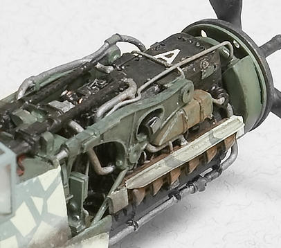 I scratch build a circular bracket round the coolant reservoir. This is only
necessary when you leave off all of the front cowlings, otherwise the
coolant reservoir and its bracket will be obscured by them. It is just as
well to leave them off by the way, as the front cowlings are far from
circular and will not align with the spinner plate. The spinner plate is
supposed to be attached to the front cowling, and with
this absent I attached it with the help of a brass pin. The pin will also
double as a piece of the barrel of the 20mm canon. Painting was done as I
went along. Most of it is semi gloss black to which I added a
tiny bit of gun metal. All plumbing was painted aluminium. Some very subtle
drybrushing was done and I made an “A” out of a piece of white decal. The
rust was simulated with the help of pigment powder. After this the assembly
of the firewall was child’s play. Well, apart from getting the pieces off
that wretched wafer that is. Just be careful though as the attachment
structure for the main landing gear is very delicate indeed.
I scratch build a circular bracket round the coolant reservoir. This is only
necessary when you leave off all of the front cowlings, otherwise the
coolant reservoir and its bracket will be obscured by them. It is just as
well to leave them off by the way, as the front cowlings are far from
circular and will not align with the spinner plate. The spinner plate is
supposed to be attached to the front cowling, and with
this absent I attached it with the help of a brass pin. The pin will also
double as a piece of the barrel of the 20mm canon. Painting was done as I
went along. Most of it is semi gloss black to which I added a
tiny bit of gun metal. All plumbing was painted aluminium. Some very subtle
drybrushing was done and I made an “A” out of a piece of white decal. The
rust was simulated with the help of pigment powder. After this the assembly
of the firewall was child’s play. Well, apart from getting the pieces off
that wretched wafer that is. Just be careful though as the attachment
structure for the main landing gear is very delicate indeed.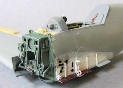 he cowlings in
front of the firewall. The wing root on the portside had to be cut off as
well. This then had to be faired over with Evergreen sheet
followed by a lot of putty, sand, repeat. Some of the underwing fairings
stick out from underneath and are quite visible. There’s also the depression
for the attachment point of the wing. So I replaced the
plastic with wine bottle foil to get a better in scale thickness, and
embossed the depression with the help of the original plastic part. The
eyelets were once again made out of Evergreen sheet and the lightening holes
were made twisting a no. 11 blade until the desired diameter. All cabling
and wiring was left off till a later date. I opened up the compass
compartment and made some internal detail (no compass though, as I initially
thought it was the radio compartment and kept wondering why I was unable to
find any reference for it). Finally the firewall and the gundeck were put
into place. As I build the model minus the port wing, the installing of the
firewall took some slight adjustments. In fact, the position of the main
landing gear structure is now not entirely correct, as the firewall is
designed to fit in between the two fuselage halves. In reality the beginning
of this structure sits flush with the skin of the aeroplane, whereas the
model shows a step of about 1mm (indeed, the thickness of the plastic
fuselage half). I could have corrected for this, but then it would have been
obvious the port and
starboard side were asymmetrical. Then I figured that nobody would know
these kinds of things anyway and didn’t bother. The gundeck by the way,
should not be cut along dashed line if not using part 23, as Verlinden would
have you do. Perhaps you could do so if you were using part 23
(the gundeck cowling), but even then I would favour sanding it to fit
instead of cutting it all together. I spruced up the gundeck a little by
adding fine copper wire to simulate the many electrical cables.
he cowlings in
front of the firewall. The wing root on the portside had to be cut off as
well. This then had to be faired over with Evergreen sheet
followed by a lot of putty, sand, repeat. Some of the underwing fairings
stick out from underneath and are quite visible. There’s also the depression
for the attachment point of the wing. So I replaced the
plastic with wine bottle foil to get a better in scale thickness, and
embossed the depression with the help of the original plastic part. The
eyelets were once again made out of Evergreen sheet and the lightening holes
were made twisting a no. 11 blade until the desired diameter. All cabling
and wiring was left off till a later date. I opened up the compass
compartment and made some internal detail (no compass though, as I initially
thought it was the radio compartment and kept wondering why I was unable to
find any reference for it). Finally the firewall and the gundeck were put
into place. As I build the model minus the port wing, the installing of the
firewall took some slight adjustments. In fact, the position of the main
landing gear structure is now not entirely correct, as the firewall is
designed to fit in between the two fuselage halves. In reality the beginning
of this structure sits flush with the skin of the aeroplane, whereas the
model shows a step of about 1mm (indeed, the thickness of the plastic
fuselage half). I could have corrected for this, but then it would have been
obvious the port and
starboard side were asymmetrical. Then I figured that nobody would know
these kinds of things anyway and didn’t bother. The gundeck by the way,
should not be cut along dashed line if not using part 23, as Verlinden would
have you do. Perhaps you could do so if you were using part 23
(the gundeck cowling), but even then I would favour sanding it to fit
instead of cutting it all together. I spruced up the gundeck a little by
adding fine copper wire to simulate the many electrical cables.| COLORS & MARKINGS |
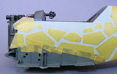 opinion Duck egg blue is the perfect approximation
(don’t let the name fool you). For the pattern of irregular polygons I
settled on a bluish grey. The rudder is definitely white, but since all the
front cowlings are removed there is no way in telling if the nose was
painted differently. Since this really could have been anything, I figured I
might just as well stick to the original scheme.
opinion Duck egg blue is the perfect approximation
(don’t let the name fool you). For the pattern of irregular polygons I
settled on a bluish grey. The rudder is definitely white, but since all the
front cowlings are removed there is no way in telling if the nose was
painted differently. Since this really could have been anything, I figured I
might just as well stick to the original scheme.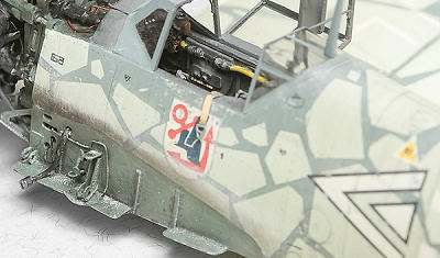 uched
up invisibly (sort of…).
uched
up invisibly (sort of…).| FINAL CONSTRUCTION |
 it in place with the
tiniest amount of glue. Then I put a dot of white paint at the end of it and
dry fitted the engine to the firewall (still without the struts, as they
would only interfere with dry fitting). This left a perfect white dot at the
rear of the engine. Quite a deep hole was drilled and a larger barrel was
firmly glued to the firewall. After a final test fitting of the engine, the
struts were glued to it with the
it in place with the
tiniest amount of glue. Then I put a dot of white paint at the end of it and
dry fitted the engine to the firewall (still without the struts, as they
would only interfere with dry fitting). This left a perfect white dot at the
rear of the engine. Quite a deep hole was drilled and a larger barrel was
firmly glued to the firewall. After a final test fitting of the engine, the
struts were glued to it with the | CONCLUSIONS |
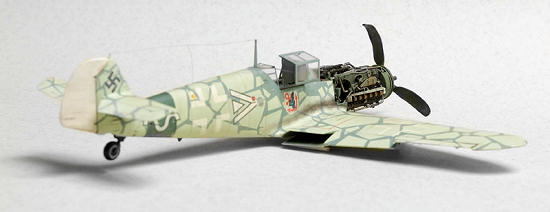
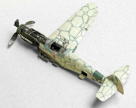
 Well, there you have it. Major Schlemiel’s plane become flesh. Albeit in
quarterscale. Believe it or not but this project kept me occupied for over
two years. I would say pretty good value for the money. The
Hasegawa kit is just superb. I cannot give it enough credits. The
Verlinden set on the other hand is a different story. The level of
detail is nowhere near that of the G6 set from Aires. Compared to that
the gun barrels from Verlinden look like featureless lumps of resin. And
then there are the lousy instructions, inaccurate parts or parts that are
missing all together… Still, with a lot of work and even more patience, a
decent model can be produced. And if it’s a G2 you want to super detail, the
Verlinden set is the only game in town as far as I’m aware of. I really
enjoyed myself and I’m actually quite pleased with the result. Now all
that’s left is building that diorama.
Well, there you have it. Major Schlemiel’s plane become flesh. Albeit in
quarterscale. Believe it or not but this project kept me occupied for over
two years. I would say pretty good value for the money. The
Hasegawa kit is just superb. I cannot give it enough credits. The
Verlinden set on the other hand is a different story. The level of
detail is nowhere near that of the G6 set from Aires. Compared to that
the gun barrels from Verlinden look like featureless lumps of resin. And
then there are the lousy instructions, inaccurate parts or parts that are
missing all together… Still, with a lot of work and even more patience, a
decent model can be produced. And if it’s a G2 you want to super detail, the
Verlinden set is the only game in town as far as I’m aware of. I really
enjoyed myself and I’m actually quite pleased with the result. Now all
that’s left is building that diorama.| REFERENCES |
If you would like your product reviewed fairly and quickly, please contact me or see other details in the Note to Contributors.