Revell 1/32 FW-190D-9
|
KIT # |
H-215 |
|
PRICE: |
Around $5 when new in the late 60s |
|
DECALS: |
? |
|
REVIEWER: |
Rick Brownlee |
|
NOTES: |
LOTS of extra work |
|
BACKGROUND |
Now that the 1/32nd Hasegawa kit is out there, I better explain why I decided to build the very old Revell kit. First of all, the Revell kit came with a Jumo 213 engine. It was my desire to open up the engine cowling and scratch-build the additional hoses and coolant/oil tanks to make the Dora more eye-catching, so to speak. Secondly, I started the Revell kit almost two and a half years ago in June of 2001 for our local contest here in the Kansas City area. It took first in category. And that was some time before I even knew that the new Hasegawa kit would be released. Glad my Dora was done before the new Hasegawa kit was on the market.
I had also purchased the 1/32nd Hasegawa Dora kit and the Verlinden Detail Set for the Dora. Before I started work I examined closely both the Revell and the Hasegawa to see what kit offered the best airframe for what I intended to do. Although there are raised rivets on the Revell kit and raised panel lines, I decided to use that kit. It is a given that "Hindsight is always 20-20", right? . . . Ahem. . . NOW, I wish I would have sanded off all the rivets and rescribed the panel lines! But it's a minor irritation.
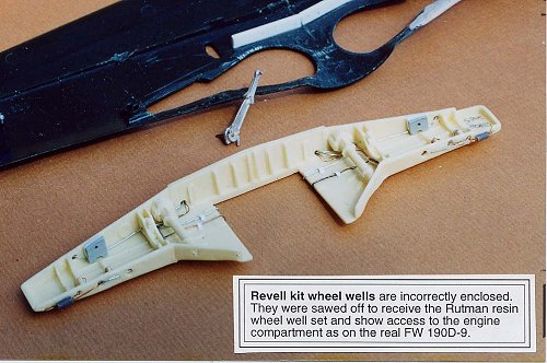
For reference, I used the "Marian Krzyzan Aircraft Monograph #6" on the Dora and the Ta 152. It is a very good reference. Also, I strongly recommend the Squadron Signal "Walk Around" book (# 10) on the Dora. It is a wonderful reference for anyone wanting to build the Dora. It contains some great color photos of the restored Dora, 12 inches equals a foot scale. And both books have excellent color renderings of eye-catching profiles. The Squadron Signal book clearly shows that a portion of the wheel wells were open. Like several of the Dora kits available out there today, the Revell kit has the wheel wells closed in as I think they should be on the radial engined FW 190 A-8 aircraft. The photos I've seen make me feel you should be able to see the bottom of the engine, supercharger and oil tank if you look up through that opening from below.
|
THE KIT |
Needless to say, the old Revell kit of the FW-190D-9 was even more inaccurate than the somewhat later Hasegawa version (first incarnation with raised panel lines, not the really new one). However, it had the benefit of being somewhat easier to find and it cost less. In fact, it had become a bit of a collector's item and from time to time sold well in that regard. It came complete with an engine and a pilot figure. No working parts other than the prop and wheels. No options other than a drop tank. The kit decals were less than exemplary and finding aftermarket versions were nearly impossible, most modelers managing to pluck bits and pieces from the other 1/32 sheets that Microscale (now Superscale) managed to produce.
|
CONSTRUCTION |
The picture below shows the work I did on
the engine cowl area. Most of the time was spent fabricating this portion
of the kit. I needed two Revell kits to do this. I built the first Revell
kit with the fuselage halves glued together, then used a hot knife to cut
off the appropriate places in order to use those engine cowl parts as
patterns to vacuform new thinner port and starboard individual engine
cowls, on my Mattel Vac-u-form. Thus it was possible to show them in the
opened position. See the image to the right and down for the completed,
painted engine cowlings) However, I would now recommend using a jewelers
saw instead of a hot knife for this chore, . . . I emphasize the word
chore. The jewelers s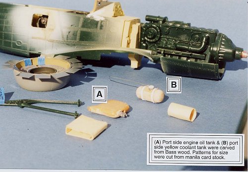 aw
allows you to get closer to the spot where you want to cut without fear
of melting the wrong area of the kit. Therefore you don't have to sand so
much of the remaining plastic to be removed. I also used the hot knife
for the top cowl (meaning the piece with the two openings that receive
the muzzles of the two MG 131 13mm machine guns placed atop and aft of
the engine) to make a pattern to vac-u-form. Mattel's Vac-u-form is a
great little machine, but is now hard to find. I purchased mine in 1966
from the Sears Christmas catalog. That
aw
allows you to get closer to the spot where you want to cut without fear
of melting the wrong area of the kit. Therefore you don't have to sand so
much of the remaining plastic to be removed. I also used the hot knife
for the top cowl (meaning the piece with the two openings that receive
the muzzles of the two MG 131 13mm machine guns placed atop and aft of
the engine) to make a pattern to vac-u-form. Mattel's Vac-u-form is a
great little machine, but is now hard to find. I purchased mine in 1966
from the Sears Christmas catalog. That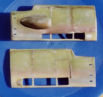 should indicate that I am now a "senior citizen/old person, retired with
time to model". My Mattel Vac-u-form still works just great. You can
also see the paper patterns (in the foreground) I fashioned to fit into
the engine compartments to help me carve the correct size and shape with
bass wood for the oil tank and coolant tank. It took two tries carving
bass wood to get the coolant tank (marked 'B') the right size. Over the
years I have learned to make patterns for floors, bulkheads, etc. out of
manila folder paper first. It is easy to cut paper with scissors and dry
fit them in the model until you have the curved area to fit just snug in
your model. Then I make the piece in plastic easily with the help of the
paper pattern.
should indicate that I am now a "senior citizen/old person, retired with
time to model". My Mattel Vac-u-form still works just great. You can
also see the paper patterns (in the foreground) I fashioned to fit into
the engine compartments to help me carve the correct size and shape with
bass wood for the oil tank and coolant tank. It took two tries carving
bass wood to get the coolant tank (marked 'B') the right size. Over the
years I have learned to make patterns for floors, bulkheads, etc. out of
manila folder paper first. It is easy to cut paper with scissors and dry
fit them in the model until you have the curved area to fit just snug in
your model. Then I make the piece in plastic easily with the help of the
paper pattern.
In the above image, you can also see as you look aft, that I have cut out the radio hatch and cut off the Revell fuselage hood wherein the instrument panel is located. I replaced it with the Verlinden piece. I had to do that in order to use the Hasegawa canopy which all the Verlinden PE parts were made for. The nose circular cowl and the PE engine cowl flaps are from the Hasegawa kit. I also used the propeller/spinner, wheels, landing gear, landing gear doors and tail wheel from the Hasegawa kit. These parts are not shown in this picture.
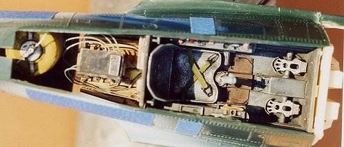 This is the
completed cockpit shown from above with the fuselage halves glued
together. Not shown are the Verlinden resin and PE parts for the
longerons, bulkheads, crank, gyro-compass, and fuselage auxiliary 115
liter fuel tank attached to the port side fuselage half and viewed
through the hatch. However, you can see in this photo the radio, wiring
and radio holding platform from above. The wires, (attached to the
auxiliary fuel tank) the electrical circuitry inside the starboard
fuselage and wiring attached to the radio were steel and copper wire. The
resin parts were painted before installing. However, the PE longerons and
bulkheads (not shown) were glued into the fuselage and then airbrushed
along with the interior of the aft fuselage in the appropriate color.
Then I sprayed a barrier layer of 3 parts mineral spirits to two parts
Flat Varnish (not Satin varnish, but FLAT varnish) This is then allowed
to dry for 48 hours. Two days later I used artist tube oil paint washes
to weather the interior of the hatch areas. The wash is mixed in a
plastic palette with dimpled recesses. (The Verlinden PE hatch doors were
installed last; at the end of the build, right after stretching the sprue
for the slack antenna Ñ and by the way, with open canopy, I believe a
slack antenna is correct for the "blown" hood on the Dora.) The cockpit
was weathered the same way as mentioned above w/ the interior fuselage
aft of the cockpit. Seat belts were made from wine bottle foil. I usually
sand the printed side of the foil to accept paint easier. This foil is
easy to super glue or bend into casual, more candid shapes. Personally, I
don't care for the decal printed seat belts or seat belts molded into the
seat. Those styles aren't as realistic looking to me. This picture of the
cockpit from overhead shows only the seat belts with PE buckles. The
shoulder harness belts with hardware were added much later.
This is the
completed cockpit shown from above with the fuselage halves glued
together. Not shown are the Verlinden resin and PE parts for the
longerons, bulkheads, crank, gyro-compass, and fuselage auxiliary 115
liter fuel tank attached to the port side fuselage half and viewed
through the hatch. However, you can see in this photo the radio, wiring
and radio holding platform from above. The wires, (attached to the
auxiliary fuel tank) the electrical circuitry inside the starboard
fuselage and wiring attached to the radio were steel and copper wire. The
resin parts were painted before installing. However, the PE longerons and
bulkheads (not shown) were glued into the fuselage and then airbrushed
along with the interior of the aft fuselage in the appropriate color.
Then I sprayed a barrier layer of 3 parts mineral spirits to two parts
Flat Varnish (not Satin varnish, but FLAT varnish) This is then allowed
to dry for 48 hours. Two days later I used artist tube oil paint washes
to weather the interior of the hatch areas. The wash is mixed in a
plastic palette with dimpled recesses. (The Verlinden PE hatch doors were
installed last; at the end of the build, right after stretching the sprue
for the slack antenna Ñ and by the way, with open canopy, I believe a
slack antenna is correct for the "blown" hood on the Dora.) The cockpit
was weathered the same way as mentioned above w/ the interior fuselage
aft of the cockpit. Seat belts were made from wine bottle foil. I usually
sand the printed side of the foil to accept paint easier. This foil is
easy to super glue or bend into casual, more candid shapes. Personally, I
don't care for the decal printed seat belts or seat belts molded into the
seat. Those styles aren't as realistic looking to me. This picture of the
cockpit from overhead shows only the seat belts with PE buckles. The
shoulder harness belts with hardware were added much later.
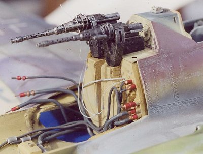 This photo
shows the two Verlinden MG 131 13mm machine guns in place but not glued
down. Also you can see the Verlinden resin MG magazines right below the
13mm machine guns. I had a lot of trouble getting everything to be at the
correct height in this area Ñ so the bottom of the 13mm guns would mate
with the top of the ammo magazines. There were several days of dryfitting,
dryfitting, more shims installed, more dryfitting, etc. On the plus
side, I now understand that there is a positive aspect about doing this
long project: I learned to exercise more patience. And the finished
product gave me more confidence in building models since the Dora was
completed.
This photo
shows the two Verlinden MG 131 13mm machine guns in place but not glued
down. Also you can see the Verlinden resin MG magazines right below the
13mm machine guns. I had a lot of trouble getting everything to be at the
correct height in this area Ñ so the bottom of the 13mm guns would mate
with the top of the ammo magazines. There were several days of dryfitting,
dryfitting, more shims installed, more dryfitting, etc. On the plus
side, I now understand that there is a positive aspect about doing this
long project: I learned to exercise more patience. And the finished
product gave me more confidence in building models since the Dora was
completed.
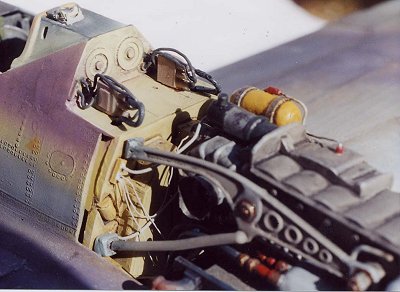
The hoses are made from various diameters of solder (purchased from Radio Shack). My North Carolina and Los Angeles email friends suggested solder instead of metal wire. It is very hard to get metal wire like steel or copper wire to bend at the proper angle or location without getting kinks or unwanted bends in the wire. Solder will cooperate and bend as you want it to. It can be easily painted before installation, and then touched up later if necessary Ñ paint will scratch off solder rather easily. I drilled tiny holes in the ends of each solder piece, then superglued very small diameter brass rod into the hole. Then I drilled holes in the plastic fire wall or portion of the kit engine where the solder hose was supposed to attach. That way I could dry fit the engine, hoses, coolant tank, etc. and see what kind of clearance I had prior to gluing. Also, once glued, the brass pins gave the joint a much stronger bond.
Most often, when using super glue I use the accelerator to speed up drying time. However, I don't spray it on with the atomizer top as that can waste too much of an expensive liquid. I fashioned an eyelet shaped applicator from steel wire. (Some modelers use the eye of a large needle.) This end is dipped into the accelerator bottle and then placed in the corner of the superglue previously touched to the model joint. I tilt the model so that gravity will allow the accelerator to "stream" toward each area of super glue. To beginners, perhaps I should say that I squeeze a few drops of super glue from the tube on to a sheet of bond paper. I use a sharpened point of a toothpick to pick up a tiny drop of superglue and place it at the joint of the two parts. Then, if needed I apply accelerator. After good and dry, I apply Testors Dull Coat with a number zero paint brush. This takes the shine off the dried super glue. A very important step for a contest modeler. Glue stains are a major gig.
Using super glue as a gap filling
material: When I attached the wings to the fuselage, there were one
fourth inch gaps on both sides where the wing root met the fuselage. I
used superglue and accelerator to hold the wing in place on the fuselage.
Then I cut and sanded several lengths of 20 thousandths sheet styrene
that were glued into the "trenches" to take
 up room. I then used
several applications of super glue and accelerator with time in between
to let each layer set up real hard, as a means of filling the gaps. The
superglue dries clear. It also makes a very strong bond. A lot of sanding
and spraying with silver paint ensued; at least 7 to 10 times before the
wing roots were smooth. (Airbrushed silver paint reveals all the flaws.)
That was one of the most painstaking exercises during the build, but
discipline is necessary to improve skills in plastic modeling. I've read
many articles where the builder explains a difficult task and says how
it's fun and EASY. I think that plastic modeling is fun but I would not
call it easy. My opinion is that in life, anything really worthwhile or
of great value will not come easy. And model building bears that out, in
my opinion.
up room. I then used
several applications of super glue and accelerator with time in between
to let each layer set up real hard, as a means of filling the gaps. The
superglue dries clear. It also makes a very strong bond. A lot of sanding
and spraying with silver paint ensued; at least 7 to 10 times before the
wing roots were smooth. (Airbrushed silver paint reveals all the flaws.)
That was one of the most painstaking exercises during the build, but
discipline is necessary to improve skills in plastic modeling. I've read
many articles where the builder explains a difficult task and says how
it's fun and EASY. I think that plastic modeling is fun but I would not
call it easy. My opinion is that in life, anything really worthwhile or
of great value will not come easy. And model building bears that out, in
my opinion.
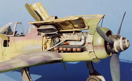
These photos shows the installed kit engine with the scratch
built oil and coolant tanks and stretched sprue electrical wiring. The
engine mounts are from the Revell kit. They were too short and it was a
problem lengthening them. A lot of dryfitting, dryfitting, dryfitting in
this area as well.
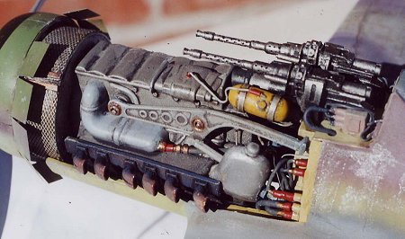 I used the Revell
kit exhaust stacks and cut out the openings in the end of each pipe by
drilling tiny holes in each end of the oval and then using a hobby knife
to carve the opening bigger. The #9 photo shows the circular screened
radiator between the engine and the propeller. I used a circle template
to draw a penciled circle on 20 thousands sheet styrene and then another
smaller circle in the center of that same piece that was cut and sanded
to fit over the propeller shaft housing. I made two of these pieces and
put thick plastic rectangular lengths from Evergreen Products to separate
the two circles at the correct distance. I use dividers to measure all
the distances and dry fit a lot as said before. I then cut brass
mesh screen to size and wrapped it around the two circular pieces using
superglue and accelerator as I worked around the circle.
I used the Revell
kit exhaust stacks and cut out the openings in the end of each pipe by
drilling tiny holes in each end of the oval and then using a hobby knife
to carve the opening bigger. The #9 photo shows the circular screened
radiator between the engine and the propeller. I used a circle template
to draw a penciled circle on 20 thousands sheet styrene and then another
smaller circle in the center of that same piece that was cut and sanded
to fit over the propeller shaft housing. I made two of these pieces and
put thick plastic rectangular lengths from Evergreen Products to separate
the two circles at the correct distance. I use dividers to measure all
the distances and dry fit a lot as said before. I then cut brass
mesh screen to size and wrapped it around the two circular pieces using
superglue and accelerator as I worked around the circle.
|
CAMOUFLAGE & MARKINGS |
 This photo shows
the engine cowl area of the completed model from the starboard side. Most
of the time, I mix my own colors; in small empty Testors Model Master
bottles. I should mention that when mixing colors for the exterior of the
model, I made the colors lighter to take into account that it was very
late in the War, the last year, 1945, of WWII. The Doras were rather
worn and parked outside in the sun. I feel that photos bear this out. So
I added drops of white to the colors (RLM 75-gray violet, RLM 76-light
blue, RLM 81-brown violet, RLM 84-green blue and RLM 82-bright green as
shown on pg. 69 of the Sqd. Signal #10 book) to give the illusion of
faded camouflage.
This photo shows
the engine cowl area of the completed model from the starboard side. Most
of the time, I mix my own colors; in small empty Testors Model Master
bottles. I should mention that when mixing colors for the exterior of the
model, I made the colors lighter to take into account that it was very
late in the War, the last year, 1945, of WWII. The Doras were rather
worn and parked outside in the sun. I feel that photos bear this out. So
I added drops of white to the colors (RLM 75-gray violet, RLM 76-light
blue, RLM 81-brown violet, RLM 84-green blue and RLM 82-bright green as
shown on pg. 69 of the Sqd. Signal #10 book) to give the illusion of
faded camouflage.
Chipping of paint was achieved with drybrushing Testors flat Aluminum around leading edges of the wings, nose, spinner, (On some of the real aircraft, the prop was made of wood. So, an indication of paint chipping/wear on my kit prop wasn't done) and more drybrushing around bulges (such as on the rounded tops of the wing cannon access doors) to give the illusion of paint wear so the aluminum skin would show thru in subtle ways.
Now, to me, that means that the markings can NOT be applied with decals. I feel you need consistency between a heavily weathered model and the markings on that model. It is easy to make a decal look dirty. But it's very difficult to make a decal look faded like the rest of the camouflage on the model Ñ to create the illusion that the marking is wearing off and that the paint underneath is showing through. On the real planes the marking were sprayed over templates and that is how I apply my markings. I make templates from paint masking tape ( 3M or Ace Hardware Blue tape), Frisket paper or from Paratone paper made by Zip-a-tone. Paratone can be purchased in professional art supply stores. Frisket paper is not very strong so it is hard to remove and reposition on another part of the model. Of course, Paratone and Frisket paper are transparent and easier to place correctly than tape. But low tack blue masking tape is stronger and can be used many times. By spraying on the markings, I can also make each marking light toned and faded. I haven't seen a lot of models done this way, but I feel it is essential for the model to successfully create the illusion of being like the real thing. If I want the camouflage to appear worn and faded in tone it follows that the markings should look the same way. Factory fresh paint schemes look great. I enjoy looking at those models. But I'm no longer interested in painting models that way. So I pick aircraft model subjects in theaters where they were grossly affected by the elements. In my view, a good weathering job is very hard to do. And I only know one way to learn how to do it well. That means you have to paint a lot of weathered models. Hopefully, each one gets better. But it does require patience to do markings in this manner. Now, if you like a factory fresh paint job, that is fine with me. I like all approaches. At this point, I hope to master weathering techniques at some point, if I live long enough.
After airbrushing the markings on the model, I also sprayed the barrier layer over the entire model's exterior and allowed it to sit for 48 hours. Then I used tube oil paint washes on both top and bottom. I don't use black oil paint to weather or accentuate the ailerons or rudder hinge recesses, etc. It is too dark at this scale, in my view. I use Paynes Gray mixed with white and a dab of Raw Umber to make the oil washes for areas of the model that have the dark color paint. I use a lighter mix of the oil wash on the areas of the model where the painted surface is lighter, like the underside. I'm saying here that I don't use the same oil wash all over the whole model. In my view, the Paynes Gray oil wash would be too pronounced, look out of scale, would kill the "illusion" so to speak, applied to the RLM 84 Green-Blue undersides.
|
CONCLUSIONS |
So with the $3 paid to a vendor table three years ago, the Hasegawa kit, the Verlinden detail set, the paints and all the film I shot and processed, the cost was around $200. If I divide that by the number of hours spent on the model, it comes to about seventy some cents per hour. And that is rather inexpensive entertainment in my book!
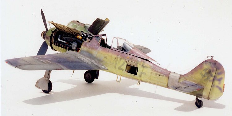
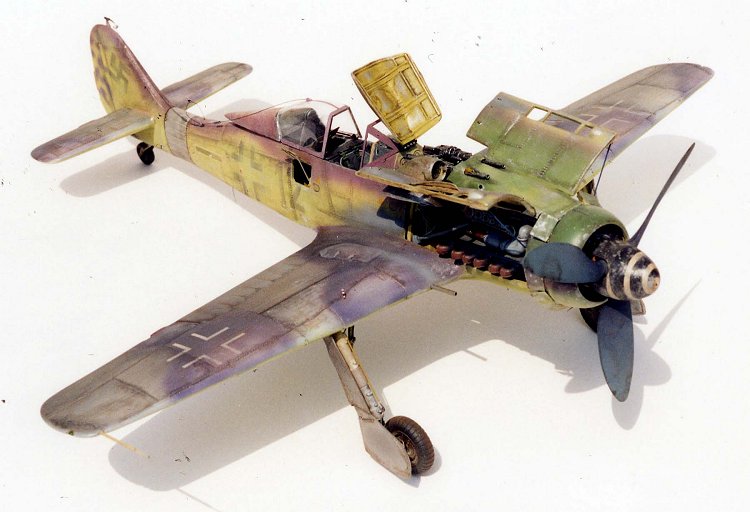
The final picture shows the completed model after 380 hours, over a period of nine months; a real learning experience! Hopefully, if you look very closely you can see the faded black numeral 12 on the starboard side and the faded swastika on the vertical tail. This is the first time I've tried to add an open cowled engine and open fuselage hatches on a large 1/32nd scale model. Also it is the most time I've ever spent on a kit. Although the model has too many flaws to win at the IPMS Nationals, and I've since found out that the dihedral is too flat on the wings, which is a major "basic construction flaw", I feel it was worth while and a great exercise in learning how to improve my skills as a modeler.
|
MATERIALS |
Gerald Rutman, HC88 Box 38, Pocono Lake, PA. 18347.
Winsor and Newton tube oil paints
Humbrol enamels and Testors enamels
Zip Kicker - Accelerator for Super Glue, Pacer Technology, Rancho Cucamonga, CA. 91730
SureHold Super Glue; distributed by Surehold, a div. of Barristo Ltd. Chicago, IL 60611
Tenax-7R liquid glue of Hohenwald, Tennessee
|
REFERENCES |
1. FW 190D/ Ta 152, Krzyzan, AJ Press (Poland) A/C Monograph 6, 1997
2. FW 190D, Ryle/Laing, Squadron/Signal Walk Around 10, 1997
November 2003
If you would like your product reviewed fairly and fairly quickly , please contact the editor or see other details in the Note to Contributors.