|
KIT # |
5949 |
|
PRICE: |
$22.00 |
|
DECALS: |
See Review |
|
REVIEW : |
Kelly Jamison |
|
NOTES: |
` |
|
HISTORY |
Much has been written on the Butcher Bird so I will write about just this type of Wurger. The Jabo-Rei Fw190G-2 was a follow on of the Fw190A-5/U8 version of this highly adaptable fighter. It had a slightly longer fuselage than its predecessor. It was armed with two MG 151 cannons in the wing roots and Flame dampers for night time operations. Only 470 copies of this aircraft were built. The G-3 Long Range Fighter Bomber version was a follow-on to the Fw190A-5/U13 and were fitted with the Fw190A-6 produced wings. It also had two MG 151 machine guns and a PKS 11 autopilot. It was equipped with two 300 liter drop tanks and a bomb rack for a 1000kg bomb or two 250kg bomb load. It was known to have carried bombs weighing up to 1800kg!
|
THE KIT |
 The kit is the Trimaster/Dragon/DML and now the ProModeler kit. The molds are
getting a bit tired and the panel lines are not as sharp as they once were. It
is still a very good kit and well worth building unless you want to build that
Trimaster kit that could send little Joey to college in a few years with
collectors prices on the rise. The aftermarket community supports this kit well
with many resin pieces, metal exhaust, decals and detail sets so adding to the
kit is no problem.
The kit is the Trimaster/Dragon/DML and now the ProModeler kit. The molds are
getting a bit tired and the panel lines are not as sharp as they once were. It
is still a very good kit and well worth building unless you want to build that
Trimaster kit that could send little Joey to college in a few years with
collectors prices on the rise. The aftermarket community supports this kit well
with many resin pieces, metal exhaust, decals and detail sets so adding to the
kit is no problem.
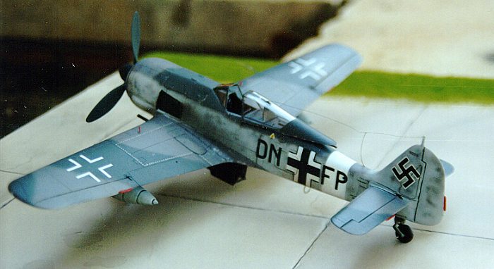
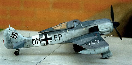
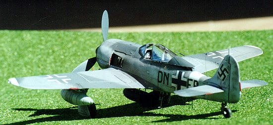
I started this kit in the usual way. Research! I spent hours pouring over pictures and flipping through books and magazines. I could not find anything that inspired me to build a G-2 or G-3 version of this kit. I decided to model one of the planes on the back of the ProModeler box. I kinda like the stark radio call letters and plain white stripe around the tail and under the engine cowl. So, a G-3 by the name of Black DN+FP of SG4, Italy, 1943 will be my next victim. I found pictures of this aircraft in a National Air and Space Museum book called "Focke-Wulf Fw190 Workhorse of the Luftwaffe Volume 9". It was captured and sent back to Wright Field and assigned the number EB-104. It became the favorite ride of many test pilots including Major Richard Bong, Bob Hoover and Chuck Yeager.
|
CONSTRUCTION |
On this kit I changed my construction techniques just a bit. Using Testors Model Masters Acryl paints, I rounded up everything that needed to be painted RLM 66 Dark Gray. I cleaned up any flash and mold lines then taped them down to a small piece of backing board and airbrushed them all. While they were drying, I went after all the parts that need to be painted RLM 22 Flat Black and started cleaning them up. RLM 02 Medium Gray was the next color to be used on all exterior parts. In short time I had quite the assembly line going with the dried parts awaiting installation. Each different color had its own backing board that was set off to the side after painting. If you have cats or small children, you might have to modify this system.
 The cockpit came in 10 parts. All painted RLM 66. The instruction sheet has a
nice exploded view of the assembly and enlarged drawings of the instrument panel
and side panels. There is a reference picture of the cockpit on the instruction
sheet but it is from the NASM Fw190F-8. Using restored aircraft as your
reference is always a very risky thing to do. Even though NASM has a very good
reputation for accuracy, they are only as accurate as the data that they use.
Which, as you know can be confusing at best with Luftwaffe aircraft, especially
during the late war years. (Editor's Note: What Kelly says is very true of
warbirds, however, I'd take what the Smithsonian finds as gospel in their more
recent restorations of the last 20 or so years. They carefully sand down to the
bare metal noting each color as they come across it.) Fw190s had many different cockpit variations.
Instrument bezels were painted black except for the middle row, far right bezel
that is painted red. With German cockpits come a color code of systems and
sub-systems. Red is for emergency systems. While blue is pneumatic air, yellow
being coolant and brown being oil.
The cockpit came in 10 parts. All painted RLM 66. The instruction sheet has a
nice exploded view of the assembly and enlarged drawings of the instrument panel
and side panels. There is a reference picture of the cockpit on the instruction
sheet but it is from the NASM Fw190F-8. Using restored aircraft as your
reference is always a very risky thing to do. Even though NASM has a very good
reputation for accuracy, they are only as accurate as the data that they use.
Which, as you know can be confusing at best with Luftwaffe aircraft, especially
during the late war years. (Editor's Note: What Kelly says is very true of
warbirds, however, I'd take what the Smithsonian finds as gospel in their more
recent restorations of the last 20 or so years. They carefully sand down to the
bare metal noting each color as they come across it.) Fw190s had many different cockpit variations.
Instrument bezels were painted black except for the middle row, far right bezel
that is painted red. With German cockpits come a color code of systems and
sub-systems. Red is for emergency systems. While blue is pneumatic air, yellow
being coolant and brown being oil.
Riffling through my decal box I unearthed my Monogram Decal Sheet 88-1017, German Instrument Panels. I located the proper gauges for the instrument panel and placed it in the bezels. Carefully dabbing a small dollop of Micro Kristal Klear over each instrument to simulate glass completed the instrument panel. Each side panel was painted RLM 66 and dry brushed gray. I added a small throttle from wire to add to the cockpit detail just a tad. A quick wash of light gray in the cockpit tub gave the detail a boost. The seat and armor back plate assembled easily and fit snugly in the tub. I did not glue this down yet so as to take it out at a later date and put seatbelts on the seat. The rudder pedals are adequate in appearance. I painted them RLM 66 and used a very small dab of Rub n’ Buff to give them a worn appearance. Using thin foil I made two straps that attach to the foot petals. I have always wondered how pilots strapped their feet to the petals in the extremely confined cockpit of the Fw190. The stick was painted RLM 66 with a black handle and fits into a small hole in the floorboard of the cockpit tub.
 The next step is to put the two fuselage halves together. The instructions
call for the tail wheel to be put in place now but I am going to hold off on
that little sub assembly until after all the sanding is accomplished. There is a
small hand crank that is used for opening and closing the canopy that needs to
be placed on a small tab located on the right side of the fuselage wall. I test
fitted the fuselage halves to see how well they lined up temporarily tacking
them together with tape. The cockpit tub was moved into position and seemed to
be too wide. After looking a little closer I noticed that the cockpit tub is
used to keep the fuselage spread apart. With that done, it is time to glue the
two fuselage halves together. There is a bulkhead that is inserted at the
beginning of the fuselage. This helps keep the shape to the forward fuselage. At
this step in construction the instructions call for the installation of the
cockpit turtledeck, the flat area behind the pilot covered by the canopy. Again,
I think I will wait until after painting the exterior to put it on.
The next step is to put the two fuselage halves together. The instructions
call for the tail wheel to be put in place now but I am going to hold off on
that little sub assembly until after all the sanding is accomplished. There is a
small hand crank that is used for opening and closing the canopy that needs to
be placed on a small tab located on the right side of the fuselage wall. I test
fitted the fuselage halves to see how well they lined up temporarily tacking
them together with tape. The cockpit tub was moved into position and seemed to
be too wide. After looking a little closer I noticed that the cockpit tub is
used to keep the fuselage spread apart. With that done, it is time to glue the
two fuselage halves together. There is a bulkhead that is inserted at the
beginning of the fuselage. This helps keep the shape to the forward fuselage. At
this step in construction the instructions call for the installation of the
cockpit turtledeck, the flat area behind the pilot covered by the canopy. Again,
I think I will wait until after painting the exterior to put it on.
The forward engine cowling is next. It was engineered to use different types of faring bulges on the side. Ones with intake carburetor filters or with the traditional bulges that we are custom to seeing, are supplied in the kit. Great care must be taken in assembly in this area. It took a few attempts to align everything up right. On the real thing this area has an imprecise fit to it anyway. I would not sweat a little misalignment. The assembled cowl is put away for installation later. Exhaust stacks are called for next. These will go back into the box awaiting final assembly.
Moving on to the landing gear wheel wells next. They are skillfully detailed and come in seven pieces including the machine gun covers that run through the wells. The center support beams are effectively done. I like the four piece frame work that spans from front to rear of the wheel wells. It adds exceedingly to the detail in this area. The pieces are small and thin, so care should be taken when installing them. I had to trim up all four brace pieces and repeatedly test fit them before gluing them down. A quick wash of dark gray and the well assembly was ready to be placed in the wing. At this point you should follow the instructions exactly. It recommends that you glue one side of the wheel well to the wing and then let it dry. Then glue the other side down setting up the dihedral of the wing. Much like a main spar would do. Good old fashion cloths pens work great here. Do not glue the forward edge of the wheel well to the wing yet. You will need it loose to better position it during mating the fuselage to the wing. Gluing the top halves to the bottom piece of the wing is straight forward construction. I still did not glue down the forward inner leading edges anticipating fit problems when the wings meet the fuselage.
 I attached the wings to the fuselage and was greeted by large gaps in the
upper wing root. No problem, I will just shim up the inside of the fuselage and
make it wider. It still didn’t fit! I came to the conclusion that this is just
a poor fitting area and placed a strip of plastic stock in the gap and sanded it
down. Because of the poor fit I had to fill up this area with Milliput. I sanded
it down and rescribed the panel lines that run down in this area. I used Rub n’
Buff to show the imperfections, then went back and patched up those areas. The
trailing edge of the bottom of the wing grafts to the lower aft fuselage with a
large gap between the two surfaces. It took a lot of putty to get the seam to
flow off the wing and taper to the fuselage just right. That forward leading
edge wing root was as I expected. A poor fit at best. Take your time and use
superglue to tack down this troublesome area. Do not superglue any part of your
body to the leading edge at this time(voice of experience). The forward edge of
the wheel well-had big gaps that I filled with Squadron White
Putty and sanded it smooth. More detail sanding with micro files needed to be
done in the wing root area. I sanded the leading edge being careful not to sand
over the gun camera ports and re-scribing the panel lines that wrap around the
curved surface of the leading edge. The cowling was the next thing to be
attached. It fit better than I thought. It needed only minor alignment and clean
up. I put the cowl ring in next making sure to align the small tab on the ring
to the 12 o’clock position. It fit flawlessly. The elevators were cleaned up
and put in place one at a time making sure each one was level.
I attached the wings to the fuselage and was greeted by large gaps in the
upper wing root. No problem, I will just shim up the inside of the fuselage and
make it wider. It still didn’t fit! I came to the conclusion that this is just
a poor fitting area and placed a strip of plastic stock in the gap and sanded it
down. Because of the poor fit I had to fill up this area with Milliput. I sanded
it down and rescribed the panel lines that run down in this area. I used Rub n’
Buff to show the imperfections, then went back and patched up those areas. The
trailing edge of the bottom of the wing grafts to the lower aft fuselage with a
large gap between the two surfaces. It took a lot of putty to get the seam to
flow off the wing and taper to the fuselage just right. That forward leading
edge wing root was as I expected. A poor fit at best. Take your time and use
superglue to tack down this troublesome area. Do not superglue any part of your
body to the leading edge at this time(voice of experience). The forward edge of
the wheel well-had big gaps that I filled with Squadron White
Putty and sanded it smooth. More detail sanding with micro files needed to be
done in the wing root area. I sanded the leading edge being careful not to sand
over the gun camera ports and re-scribing the panel lines that wrap around the
curved surface of the leading edge. The cowling was the next thing to be
attached. It fit better than I thought. It needed only minor alignment and clean
up. I put the cowl ring in next making sure to align the small tab on the ring
to the 12 o’clock position. It fit flawlessly. The elevators were cleaned up
and put in place one at a time making sure each one was level.
|
PAINT & DECALS |
 At this time I took the kit to the sink and gave it a good scrubbing with a
soft tip tooth brush to clean any debris out of the panel lines. Just a dab of
soap and a good old fashion wash got the kit in order for the primer coat. I
used the coat of Testors Acryl Primer to pinpoint and touch up any blemishes
that were missed earlier. I masked off all surfaces not to be painted with
masking tape and wet tissue paper. Testors Acryl RLM 76 was used as the base
coat for the fuselage sides, tail and underwing. Testors Acryl RLM 75 was next
then RLM 74 to finish off the camouflage. Since my reference choices were slim,
I used the box lid and instructions along with a few reference photos as a
guideline. Not 100% accurate but I think the effect was captured just fine.
At this time I took the kit to the sink and gave it a good scrubbing with a
soft tip tooth brush to clean any debris out of the panel lines. Just a dab of
soap and a good old fashion wash got the kit in order for the primer coat. I
used the coat of Testors Acryl Primer to pinpoint and touch up any blemishes
that were missed earlier. I masked off all surfaces not to be painted with
masking tape and wet tissue paper. Testors Acryl RLM 76 was used as the base
coat for the fuselage sides, tail and underwing. Testors Acryl RLM 75 was next
then RLM 74 to finish off the camouflage. Since my reference choices were slim,
I used the box lid and instructions along with a few reference photos as a
guideline. Not 100% accurate but I think the effect was captured just fine.
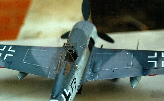
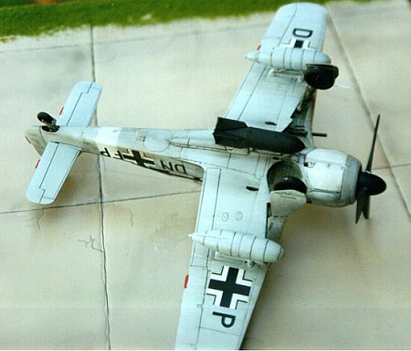
Robert Sand and the late Jeff Ethell published an excellent book called Fighter Command in Color. It gives a fantastic picture of DN+FV of the same Squadron on page 148. This picture was my major reference for my kit. I left the model to dry overnight before I put the first coat of Future Floor Polish. Make sure and keep it in a dust free environment. (This refers back to the earlier comment about cats.) The decals went on with no problem. A few of the decals came with a white background first then the main decal over that. For instance, the fuel, oil and hydraulic triangles and the swastikas on the tail use this double decal method. They went on with no problem and lined up flawlessly. Be patient with the "no walk" lines on the top of the wings. There is more than enough of those little dashed lines there to do the wings and mess up a few times in the process. The result is worth the work. They snug down with just a little SolvaSet and dried clearly. There are a lot of fantastic small stencils that come on the marvelous AeroMaster decal sheet. They really live up to their reputation. Another quick coat of Future Floor Polish embeds the decals and makes them look painted on.
|
CONSTRUCTION CONTINUES |
At this time I put the landing gear together, placing the hydraulic lines in the front of the gear strut. A quick wash of black got the weathering of the exposed surfaces in order and brought out the detail in the process. The gear fits loosely into small round buckets in the wing. They do not help set the rake or camber of the gear at all. The downlock yokes help to set the camber but you have to eyeball the rake that is hard to do without the tail wheel assembly installed. I used Ambroid ProWeld liquid glue and made a small rig out of cardboard to hold the gear in its proper place. The slower setting glue gave me time to set the gear in its right place. The inner wheel of the tail wheel is painted gloss black. Glue this onto the yokes and place it in the tail unit. I used Testors Acryl RLM 23 Rot with just a little black to tone down the red and use the new color to paint the trim tabs. Then I placed the German "no push" decals on them.
 With a pin vise I drilled out the gun ports to
accommodate 1/16 inch aluminum tubing for machine gun barrels. These were
painted with Tamiya Gun Metal and dry brushed with black pastels. Small bits of
wire were used for the landing gear down indicators that protrude from the top
of the wings and painted Badger Model Flex Caboose Red. I hand painted the prop
blades with RLM 66 Schwarzgrun. This gives the props a slight grain effect that
replicates the wooden props used. The prop retaining caps are silver and can be
seen protruding out of the spinner that I airbrushed flat black. Make sure and
align the small tabs on the prop shafts to the spinner base. This will set up
the proper blade angle.
With a pin vise I drilled out the gun ports to
accommodate 1/16 inch aluminum tubing for machine gun barrels. These were
painted with Tamiya Gun Metal and dry brushed with black pastels. Small bits of
wire were used for the landing gear down indicators that protrude from the top
of the wings and painted Badger Model Flex Caboose Red. I hand painted the prop
blades with RLM 66 Schwarzgrun. This gives the props a slight grain effect that
replicates the wooden props used. The prop retaining caps are silver and can be
seen protruding out of the spinner that I airbrushed flat black. Make sure and
align the small tabs on the prop shafts to the spinner base. This will set up
the proper blade angle.
I then manufactured a new tail antenna from some stock plastic to replace the one I broke off earlier in the building process. All chipped paint areas were done with a Marvy Metallic Gel Roller pen. It gives you a lot of control and is easy to wipe off if you overdo it or it just doesn’t look right. The exhaust stacks slide into slots in the inside of the engine cowling. I dropped the little stacks into the fuselage so many times that I ended up taking off the front cowl ring and prop assembly to gain access the interior of the engine cowling. It glued down within seconds after removing the front of the cowl. On hind sight I should have glued those down during initial assembly.
I used a set of True Detail Fast Frames to finish off the glass portions. The rear part of the canopy frame did not match up with the decal mask so I sanded off the molded lines and polished them out using different grades of sand paper. A quick dip in Future Floor Wax and all scratches went away. The headrest and retaining bar are difficult to construct and place inside of the canopy. Thin stretched spruce was added for the antenna using Kristal Klear to glue down the ends and fashion insulators. The bomb shackles and anti-sway bars of the external tanks were next. They are straight forward construction but you have to treat these areas like its own little models. The attention to detail with these mini assemblies will really pay off.
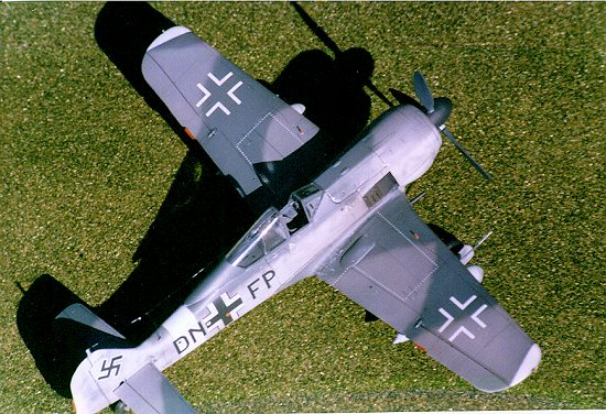
 One of the last things you want to add is
the under wing antenna, loop antenna that goes under the fuselage, along with
the small whip antenna that goes behind the loop antenna and the foot ladder
that goes just aft of the left wing root on the bottom of the fuselage. These
pieces have a habit of being broken off and easily lost. I painted the foot
ladder RLM 76 with small red stripes in the middle of the downward bars. The
drop tanks went together with just a little alignment problems. There are small
pads that glue to the top of the tank. They are tedious to work with but help
out the detail tremendously and are worth the effort. They got a coat of RLM 76
and decals stating their purpose. Once dried they were skewered onto the outer
wing shackles. The bomb went together like the drop tanks with some cursing and
sanding and a lot of filler to get the shape back to round. The small struts on
the fins are a nice touch and can be replaced with stock plastic bar if you want
to. The center bomb was painted black and glued onto the center shackle. The
wing tip navigation lights are small clear pegs that fit in holes in the wing
tip. They fit tightly and needed no glue. A quick dusting of your favorite
pastel chalks will dirty up the fuselage a bit and give the plane a nice used
look.
One of the last things you want to add is
the under wing antenna, loop antenna that goes under the fuselage, along with
the small whip antenna that goes behind the loop antenna and the foot ladder
that goes just aft of the left wing root on the bottom of the fuselage. These
pieces have a habit of being broken off and easily lost. I painted the foot
ladder RLM 76 with small red stripes in the middle of the downward bars. The
drop tanks went together with just a little alignment problems. There are small
pads that glue to the top of the tank. They are tedious to work with but help
out the detail tremendously and are worth the effort. They got a coat of RLM 76
and decals stating their purpose. Once dried they were skewered onto the outer
wing shackles. The bomb went together like the drop tanks with some cursing and
sanding and a lot of filler to get the shape back to round. The small struts on
the fins are a nice touch and can be replaced with stock plastic bar if you want
to. The center bomb was painted black and glued onto the center shackle. The
wing tip navigation lights are small clear pegs that fit in holes in the wing
tip. They fit tightly and needed no glue. A quick dusting of your favorite
pastel chalks will dirty up the fuselage a bit and give the plane a nice used
look.
|
CONCLUSIONS |
I enjoyed this model even though I was a bit frustrated by the scarce amount of reference pictures and I could not find any aftermarket decals available. AeroMaster did make a combo set of A-8’s, G-2/3’s and D-9’s but they are out of production. Maybe someone lucky can find a set. I expect with the release of the Revell G-8 that decal manufactures will not neglect the G model of the Butcher Bird. I did find through my research and after I finished the model that the wing tips should be painted white at an angle along the panel line. (Corrected at a later date) For most part the fit is good even though I was disappointed with the gap in the wing root area and forward wheel well area. I also felt the plastic was soft and the molds did not seem up to par with current new releases due to their age. The kit is widely available and is a good dollar value, selling for around $18.00. With just a little effort it makes an intensely good looking kit and is a befitting representation of the Butcher Bird.
|
REFERENCES |
Fighter Aces of the Luftwaffe Toliver & Constable
The History of German Aviation-Kurt Tank Wagner
Fighter Command Ethell and Sand
German Aircraft Interiors Vol 1 Merrick
Luftwaffe Codes, Markings & Units 1939-1945 Rosch
Copyright ModelingMadness.com. All rights reserved. No reproduction in part or in whole without express permission.
If you would like your product reviewed fairly and fairly quickly, please contact the editor or see other details in the Note to Contributors.
Back to Reviews Page 2022