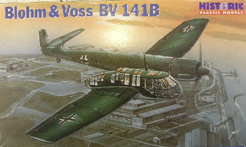
HiPM 1/48 Bv-141B
|
KIT # |
48004 |
|
PRICE: |
AU $61.00 |
|
DECALS: |
Two Options |
|
REVIEWER: |
Ewart Yong |
|
NOTES: |
Short run kit. Aires accessories used |
|
HISTORY |
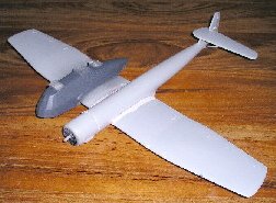
The BV-141B has to be one of the strangest looking aircraft to appear during WWII; it was designed in 1937 by Richard Vogt. It was a private venture in response to a specification issued by the RLM for a light reconnaissance and bombing aircraft for army cooperation duties. Earlier variants spotted a more conventional tail plane. This was modified to the asymmetric configuration of the B variant to improve the rear gunner’s field of fire. Unfortunately, this modification adversely affected the reportedly good handling characteristics of the prototype. At that time, the other competitor for the RLM’s specification of a light reconnaissance aircraft was the FW-189, a twin-engined /boomed aircraft of more conventional design. Eventually, the latter became operational while the BV-141 only served in evaluation squadrons and never saw any widespread operational service. The BV-141’s disfigured appearance coupled with official skepticism of such an unorthodox aircraft ensured that the design never reached full operational status and hastened the inevitable demise of this program.
|
THE KIT |
 I purchased this kit while
on vacation to Adelaide in 2001. It was the only one left on the shelves
amongst other HiPM kits. I have always wanted to build a model of this
aircraft and the only offerings till then were in 1/72nd scale
by Airfix and Bilek. Since I primarily build in 1/48th scale, I
bought this kit immediately. The esoteric nature and the asymmetrically
ugly lines of this beast endeared me to the subject almost immediately.
I purchased this kit while
on vacation to Adelaide in 2001. It was the only one left on the shelves
amongst other HiPM kits. I have always wanted to build a model of this
aircraft and the only offerings till then were in 1/72nd scale
by Airfix and Bilek. Since I primarily build in 1/48th scale, I
bought this kit immediately. The esoteric nature and the asymmetrically
ugly lines of this beast endeared me to the subject almost immediately.
The kit comes in a moderately sturdy top-opening box adorned with a not too great box art. Side flaps show photographs of the completed model and the clear molded bits and photo etched parts. What struck me upon opening the box was the size of the model, the fuselage boom almost filled up the entire length of the box and the box itself was cramped full of sprues.
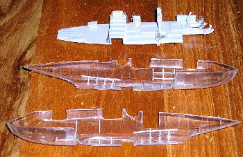
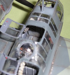
The kit is molded in a light gray hard plastic. An unusual feature of this kit is the gondola, which is molded entirely in clear plastic. The advantage of this is that there will not be any tricky placements of windows to worry about. Unfortunately, the joint line runs across two window panels. Unless these window panels are replaced, it would be impossible to eliminate this visible joint line.
Also provided is a fret of stainless steel photo-etched parts containing the instrument panel and other cockpit details, the machine gun ports for the fixed forward firing guns, the gunsight for these, optional etched torque links for the undercarriage, seat belts and the cooling fan for the engine.
The instruction sheet consists of a brief written history of this aircraft in English, a map showing the parts layout, a reasonably clear and logical step by step construction sequence and painting and decal placement guide. RLM coding is used to reference the major colours; no specific brand of paints are quoted. I personally like this since it eliminates ambiguities associated with generic descriptions like ‘dark green’ or ‘Humbrol 78’.
 Two options are provided
on the decal sheet. The decals are printed by Propagteam and opacity
looked excellent on initial inspection. Registration is a tad off and
especially noticeable on the swastikas. The latter as is common practice
these days is printed in two parts to allow the kit to be sold in the EU.
I found this strange, since the box art shows the full swastika. I had my
reservations about the decals since I have read reviews about Propagteam
decals being extremely thin and unforgiving once they are put in place,
being prone to tearing when trying to position them on the model.
Two options are provided
on the decal sheet. The decals are printed by Propagteam and opacity
looked excellent on initial inspection. Registration is a tad off and
especially noticeable on the swastikas. The latter as is common practice
these days is printed in two parts to allow the kit to be sold in the EU.
I found this strange, since the box art shows the full swastika. I had my
reservations about the decals since I have read reviews about Propagteam
decals being extremely thin and unforgiving once they are put in place,
being prone to tearing when trying to position them on the model.
A preview of this kit done by Matt Swan indicates that moldings in his example were excellent. Regrettably, this was not the case with mine. There was quite a lot of flash on the parts which needed tedious cleaning up. Numerous sink holes marred the side consoles and spare ammunition drums in my kit. Also, the transparent gondola exhibited several imperfections which necessitated tedious clean up and polishing at a latter stage.
The undercarriage oleos had lots of thick flash and the cross section was out-of-round. These are best scratch-built with brass tubing (like I did). The two MG-15 flexible machine guns were represented by shapeless blobs of plastic with lots of flash, rendering them totally unusable. These are best replaced with after-market accessories. Panel lines are recessed and quite crisply molded. Like most short-run kits, no locating pins or tabs are provided. Also the wing root joints to the engine boom and gondola are butt-jointed and it is recommended that strengthening spars fashioned from 40 thou plastic sheet be incorporated for reinforcement. This is a rather large and heavy model and the wing root joints will definitely crack if handled without any form of reinforcement in the wings.
This certainly is no shake ‘n’ bake kit….
|
CONSTRUCTION |
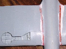 THE MAIN AIRFRAME: I
departed from the assembly sequence stated in the instructions and
assembled the fuselage boom, wings and tail plane as a complete
sub-assembly. Before assembling the wing halves, plastic strips were added
to depict framing detail in the wheel bays. A stiffening spar corresponding to the contours
of the portion where the gondola fitted was fashioned out of 40 thou
plastic card to extend right through to the wing section where the gondola
meets the fuselage boom on the port wing and up to the straight portion of
the starboard wing. The stiffening spar also served to ensure correct
alignment of the two wing sections just outboard of the gondola. If assemble
THE MAIN AIRFRAME: I
departed from the assembly sequence stated in the instructions and
assembled the fuselage boom, wings and tail plane as a complete
sub-assembly. Before assembling the wing halves, plastic strips were added
to depict framing detail in the wheel bays. A stiffening spar corresponding to the contours
of the portion where the gondola fitted was fashioned out of 40 thou
plastic card to extend right through to the wing section where the gondola
meets the fuselage boom on the port wing and up to the straight portion of
the starboard wing. The stiffening spar also served to ensure correct
alignment of the two wing sections just outboard of the gondola. If assemble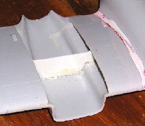 d per the
instructions, there would be a noticeable droop. This spar was glued
securely with generous applications of super glue and accelerator. The
bottom outboard panel of the starboard wing was a separate piece and the
attachment to the gondola section was reinforced with strips of plastic
sheets to ensure a strong joint. The port wing was straightforward, just
the top and lower halves which were glued together as usual. The port wing
was then attached to the fuselage boom, reinforced with brass tubing at the
leading and trailing edges through the boom and a generous application of
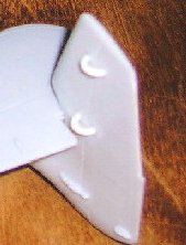
super glue at the roots. The two locating lugs on the lower half of the
tail plane were removed; if this was fitted on to the locating holes of
the vertical fin slot, the elevator hinge line will not be perpendicular to
the fuselage boom and would result in a pronounced back sweep; my
references indicate that this was not the case. The supporting strut was
fitted and the whole assembly left aside to dry. The wing root joints were
a poor fit to the fuselage boom and Milliput epoxy putty was used to smooth
this joint. At this juncture, all joints were sanded smooth and panel
lines lost in the process were restored with my scriber. I proceeded with
the engine cowl assembly. This was a tricky affair as the cowl was molded
in two halves. No engine is provided but this is of no concern
d per the
instructions, there would be a noticeable droop. This spar was glued
securely with generous applications of super glue and accelerator. The
bottom outboard panel of the starboard wing was a separate piece and the
attachment to the gondola section was reinforced with strips of plastic
sheets to ensure a strong joint. The port wing was straightforward, just
the top and lower halves which were glued together as usual. The port wing
was then attached to the fuselage boom, reinforced with brass tubing at the
leading and trailing edges through the boom and a generous application of
super glue at the roots. The two locating lugs on the lower half of the
tail plane were removed; if this was fitted on to the locating holes of
the vertical fin slot, the elevator hinge line will not be perpendicular to
the fuselage boom and would result in a pronounced back sweep; my
references indicate that this was not the case. The supporting strut was
fitted and the whole assembly left aside to dry. The wing root joints were
a poor fit to the fuselage boom and Milliput epoxy putty was used to smooth
this joint. At this juncture, all joints were sanded smooth and panel
lines lost in the process were restored with my scriber. I proceeded with
the engine cowl assembly. This was a tricky affair as the cowl was molded
in two halves. No engine is provided but this is of no concern
 since most
of the cowl opening is hidden by the large cooling fan. The cooling fan is
provided as a photo-etched part that required careful twisting to obtain
the correct pitch. This is quite a tight fit in the cowl opening and
further adjustments and bending were needed to ensure a snug fit. The
exhaust manifold was poorly molded with lots of flash, requiring tedious
cleaning up to ensure a passable fit. The more fastidious among you might
choose to replace these with hollow tubing instead. My reference photos
also indicate that the rudder hinges were of the semi-circular variety and
not the shapeless bumps depicted in the kit. These were removed and the
hinges rebuilt with plastic sheet to match the photos of my references.
since most
of the cowl opening is hidden by the large cooling fan. The cooling fan is
provided as a photo-etched part that required careful twisting to obtain
the correct pitch. This is quite a tight fit in the cowl opening and
further adjustments and bending were needed to ensure a snug fit. The
exhaust manifold was poorly molded with lots of flash, requiring tedious
cleaning up to ensure a passable fit. The more fastidious among you might
choose to replace these with hollow tubing instead. My reference photos
also indicate that the rudder hinges were of the semi-circular variety and
not the shapeless bumps depicted in the kit. These were removed and the
hinges rebuilt with plastic sheet to match the photos of my references.
 COCKPIT: The main
components of the cockpit were assembled as specified in the instructions.
At this point, I also cut away the portion of the rear cockpit floor just
under the wing spar box to accommodate the stiffening spar added in the
airframe. The pilot’s seat
had lots of flash and molding imperfections which had to be tediously
cleaned up. I considered rebuilding the seat out of plastic sheet but
decided against the idea since the ample seatbelts would hide most of the
imperfections. The trim wheel was fashioned out of copper wire and super
glued to the right side of the seat. Other enhancements to the cockpit
include addition of wiring, throttle quadrant and levers, radios added from
Aeries Luftwaffe radio sets (these are spurious according to my references,
I only got some good references from the web after I finished the cockpit)
and ribbing detail added to the wing spar box (again, these are spurious –
my references indicate a plain structure devoid of any detail). The
cockpit assembly was painted RLM 66 and a black water colour wash was
subsequently applied to accentuate details. The assembly was dry brushed
with neutral gray before other details such as the etched seat belts and
rear gunner’s padding were painted. The cockpit was then dusted with brown
pastel chalk dust to simulate dirt and grime before the whole assembly was
sprayed with Dullcote
COCKPIT: The main
components of the cockpit were assembled as specified in the instructions.
At this point, I also cut away the portion of the rear cockpit floor just
under the wing spar box to accommodate the stiffening spar added in the
airframe. The pilot’s seat
had lots of flash and molding imperfections which had to be tediously
cleaned up. I considered rebuilding the seat out of plastic sheet but
decided against the idea since the ample seatbelts would hide most of the
imperfections. The trim wheel was fashioned out of copper wire and super
glued to the right side of the seat. Other enhancements to the cockpit
include addition of wiring, throttle quadrant and levers, radios added from
Aeries Luftwaffe radio sets (these are spurious according to my references,
I only got some good references from the web after I finished the cockpit)
and ribbing detail added to the wing spar box (again, these are spurious –
my references indicate a plain structure devoid of any detail). The
cockpit assembly was painted RLM 66 and a black water colour wash was
subsequently applied to accentuate details. The assembly was dry brushed
with neutral gray before other details such as the etched seat belts and
rear gunner’s padding were painted. The cockpit was then dusted with brown
pastel chalk dust to simulate dirt and grime before the whole assembly was
sprayed with Dullcote 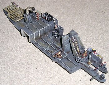 lacquer from a spray can to seal everything in . The instrument panel
assembly consisted of an etched panel with acetate sheet depicting the
instrument dials. The acetate sheet was to be sandwiched between the
photo-etched panel and injection-molded backing supplied with the other
plastic parts. The latter was discarded and replaced with plastic sheet.
Details such as the individual instrument housings and wiring were added to
the rear of the panel from sections of plastic rod and fine gauge copper
wire respectively. The entire subassembly was painted and details picked
out with a fine 00 brush.
lacquer from a spray can to seal everything in . The instrument panel
assembly consisted of an etched panel with acetate sheet depicting the
instrument dials. The acetate sheet was to be sandwiched between the
photo-etched panel and injection-molded backing supplied with the other
plastic parts. The latter was discarded and replaced with plastic sheet.
Details such as the individual instrument housings and wiring were added to
the rear of the panel from sections of plastic rod and fine gauge copper
wire respectively. The entire subassembly was painted and details picked
out with a fine 00 brush.
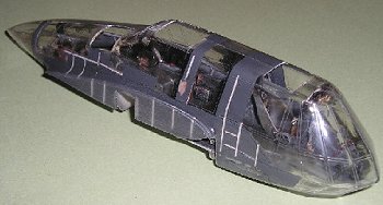
GONDOLA: As mentioned,
the transparent moldings representing the gondola had numerous
imperfections. These were wet sanded, both inside and outside with 1200
grit abrasive paper and polished with Novus 2 and 3 plastic polish. This
was a tedious process which took several evenings due to the multitude of
molding imperfections. The inside was then brushed with several coats of
Future floor polish, allowing at least two hours between coats. Even so,
the resultant finish was less than satisfactory but a vast improvement over
the original molding. With this done, I cut out a portion where the wings
fitted, corresponding to the stiffening spar added earlier. Frame details
were added from 25 thou square strips with super glue. The appropriate
window panels were masked off from the inside and sprayed with RLM 66 and
given the same treatment as the cockpit assembly to highlight and weather
the interior. At this point, the map cases, spare ammo drums and
instrument panel were fitted with superglue. Caution must
 be exercised
with the instrument panel, no locating pins or equivalent are provided and
any slip may mar one of the top window panels. Once done the photo etched
ring sight was added to the underside of the instrument panel. Location
for this was vague in the instructions and I used an educated guess in
conjunction with photos of a completed model of the FW-189 to obtain the
final position. The gun mounting rings were also added at this juncture.
Attaching the ring for the top rearward-firing gun is tricky; the opening
in the gondola halves for this need to be enlarged. Also, do not make the
same mistake as I did; the gun should be offset to the left when looking
from the rear of the gondola and not centered (like I did mine). The
excellent resin Aeries MG-15’s were added to the gun-mounting rings less
the barrels to avoid handling damage during subsequent painting and
assembly. The cockpit floor was then test fitted to the port half of the
gondola. This revealed that the cartridge collection chute for the top gun
was slightly too long. This was trimmed down until a satisfactory fit was
obtained. Once I was satisfied, the cockpit floor was super-glued to the
port half of the gondola and the two halves joined with liquid cement. With the glue fully set,
I went about the arduous task of sanding
be exercised
with the instrument panel, no locating pins or equivalent are provided and
any slip may mar one of the top window panels. Once done the photo etched
ring sight was added to the underside of the instrument panel. Location
for this was vague in the instructions and I used an educated guess in
conjunction with photos of a completed model of the FW-189 to obtain the
final position. The gun mounting rings were also added at this juncture.
Attaching the ring for the top rearward-firing gun is tricky; the opening
in the gondola halves for this need to be enlarged. Also, do not make the
same mistake as I did; the gun should be offset to the left when looking
from the rear of the gondola and not centered (like I did mine). The
excellent resin Aeries MG-15’s were added to the gun-mounting rings less
the barrels to avoid handling damage during subsequent painting and
assembly. The cockpit floor was then test fitted to the port half of the
gondola. This revealed that the cartridge collection chute for the top gun
was slightly too long. This was trimmed down until a satisfactory fit was
obtained. Once I was satisfied, the cockpit floor was super-glued to the
port half of the gondola and the two halves joined with liquid cement. With the glue fully set,
I went about the arduous task of sanding
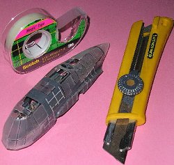 and polishing the joints. Once
done, I proceeded with the tedious job of masking all the windows. I used
Scotch frosted tape and a cutter for this purpose. This process drove me
almost blind and to the verge of insanity.
and polishing the joints. Once
done, I proceeded with the tedious job of masking all the windows. I used
Scotch frosted tape and a cutter for this purpose. This process drove me
almost blind and to the verge of insanity.
When satisfied, I proceeded with test fitting the gondola assembly to the main airframe. This is when I discovered more fit problems. The gondola was about 2 millimetres too wide to fit the opening and the wing root profile was thicker than the wings themselves. I proceeded to sand down the gondola at the wing root area with 150 grit abrasive paper to reduce the width, test fitting frequently along the way. I then attached the gondola to the wings with super glue and reinforced all joints with further application of glue and accelerator. Another anomaly was that the underside of the wings where the gondola sat was slightly too high. I proceeded to fill the wing root joints and smooth the lower portion with generous applications of plastic putty. These were wet sanded and once again, lost panel lines were restored as necessary with a scriber.
Next, I added the photo
etched gun ports to the front of the gondola and d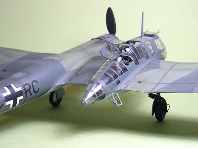 rilled
out holes for the fixed forward firing gun barrels. The latter were
simulated with hypodermic syringe needles of the appropriate lengths.
rilled
out holes for the fixed forward firing gun barrels. The latter were
simulated with hypodermic syringe needles of the appropriate lengths.
UNDERCARRIAGE: The kit parts were out of round and suffered badly from flash. Only the wheel yokes were retained from the original kit part; the main oleos were rebuilt from brass tubing of the appropriate diameter. The canvas covers on the sliding members were simulated with putty, with the creases added using a toothpick. Brake lines and harnesses were added from copper wire and lead foil respectively (this was conjectural). I chose to use the plastic torque links rather than the photo-etched ones as the latter were too thin and did not depict this component realistically. The main undercarriage was then painted, weathered and set aside. The hole in the tail wheel where the yoke fitted was off center, this was filled with plastic rod and the hole re-drilled. The wheel was then fitted to the strut, painted and set aside for final assembly.
|
CAMOUFLAGE & MARKINGS |
Prior to painting preparation, I filed a semi-circular opening on the port wing leading edge for the landing light. A piece of transparent sprue was fitted to this opening, filed and polished. Wing tip lights were added from small pieces of plastic rod shaped appropriately. I did not use clear plastic for these as I felt they were small and needed only painting to look satisfactory. The pitot tube was replaced with brass tubing and a hypodermic needle of appropriate diameters and super-glued to the wing leading edge.
 Usually at this stage, I
will wash the entire model with liquid dish washing solution. However, I
elected to depart from this usual practice for this model as I feared the
dishwashing solution might have an adverse effect on the Future polish in
the gondola. Instead, I wiped the entire model down with naptha (Zippo
lighter fluid) to remove any traces of grease, followed by a final rub
down with isopropyl alcohol. I masked off the wheel well openings with
tissue paper and the landing light with frosted tape and filled out the
various cockpit hatches with expanded polystyrene foam. I sprayed Testors
RLM 66 on the gondola
Usually at this stage, I
will wash the entire model with liquid dish washing solution. However, I
elected to depart from this usual practice for this model as I feared the
dishwashing solution might have an adverse effect on the Future polish in
the gondola. Instead, I wiped the entire model down with naptha (Zippo
lighter fluid) to remove any traces of grease, followed by a final rub
down with isopropyl alcohol. I masked off the wheel well openings with
tissue paper and the landing light with frosted tape and filled out the
various cockpit hatches with expanded polystyrene foam. I sprayed Testors
RLM 66 on the gondola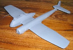 area
as I wanted this colour to show through as the internal portion of the
framing. After the paint had dried for a day, I primed the entire model
with Humbrol Neutral Gray.
The assembly was then examined for any imperfections and these were fixed
before I proceeded to the next stage. At this point, I decided to add the
aerial mast after first reinforcing it with 12 thou guitar string. After
super gluing it to the gondola, I discovered another mistake. The aerial
mast should have been offset slightly to the port side instead of mounted
centrally. I decided to live with this mistake and proceeded on. I
pre-shaded all the panel lines with black paint sprayed through my Testors
airbrush. Once done, I
sprayed the lower surfaces with Testors RLM 65 enamel, using only two thin
coats so that the pre-shading could be visible through the final coat.
When the
area
as I wanted this colour to show through as the internal portion of the
framing. After the paint had dried for a day, I primed the entire model
with Humbrol Neutral Gray.
The assembly was then examined for any imperfections and these were fixed
before I proceeded to the next stage. At this point, I decided to add the
aerial mast after first reinforcing it with 12 thou guitar string. After
super gluing it to the gondola, I discovered another mistake. The aerial
mast should have been offset slightly to the port side instead of mounted
centrally. I decided to live with this mistake and proceeded on. I
pre-shaded all the panel lines with black paint sprayed through my Testors
airbrush. Once done, I
sprayed the lower surfaces with Testors RLM 65 enamel, using only two thin
coats so that the pre-shading could be visible through the final coat.
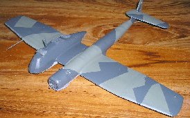
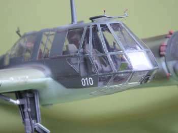
When the 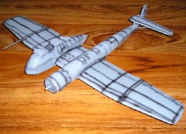 paint had set for two days, I masked off the undersides with
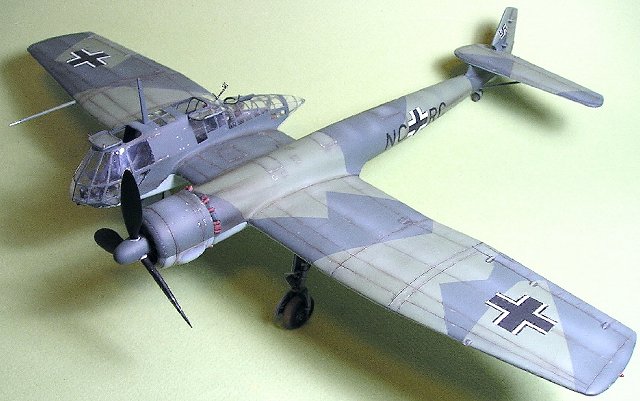
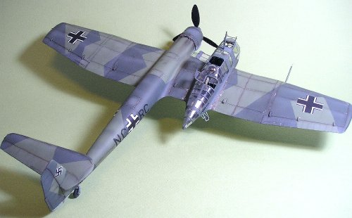
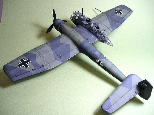
Tamiya masking tape and paper. RLM 71 was sprayed on the top surfaces in a
similar manner to allow the pre-shading to be visible. When the paint had
dried for a day, I masked the splinter pattern once again with Tamiya
masking tape. Black paint was sprayed as pre-shading over the panel lines
once again before RLM 70 was applied to the unmasked area. Once this final
colour had dried to the touch, I removed all masking save for those on the
paint had set for two days, I masked off the undersides with
Tamiya masking tape and paper. RLM 71 was sprayed on the top surfaces in a
similar manner to allow the pre-shading to be visible. When the paint had
dried for a day, I masked the splinter pattern once again with Tamiya
masking tape. Black paint was sprayed as pre-shading over the panel lines
once again before RLM 70 was applied to the unmasked area. Once this final
colour had dried to the touch, I removed all masking save for those on the
 canopy. The entire
assembly was set aside and allowed to cure thoroughly for two days before
subsequent handling. Any imperfections and over-spray were touched up
using the main camouflage colours shot selectively at the offending areas
using the finest setting of my airbrush.
canopy. The entire
assembly was set aside and allowed to cure thoroughly for two days before
subsequent handling. Any imperfections and over-spray were touched up
using the main camouflage colours shot selectively at the offending areas
using the finest setting of my airbrush.
Paint fading was simulated by carefully spraying thinned down light grey on selected panels. Paint chipping was then simulated using aluminium enamels carefully applied with a 00 brush on selected areas. Once done, the model was airbrushed with several coats of Testors Glosscote and allowed to dry for a further two days.
Decals were then applied
and thankfully, I experienced none of the problems reportedly associated
with Propagteam 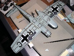 decals. These reacted very well with Aeromaster Set and
Sol decal solutions. One point of caution however is that the under wing
crosses are labeled reversed in the instruction sheet. Once the decals
have been applied and allowed to dry for a further two days, the entire
model was cleaned with Jiff kitchen cleaner and a damp cloth to remove all
traces of decal residue. Panel lines were accentuated with a diluted
black-brown water colour wash
and any excess removed with a soft cloth moistened lightly with
kitchen cleaner.
decals. These reacted very well with Aeromaster Set and
Sol decal solutions. One point of caution however is that the under wing
crosses are labeled reversed in the instruction sheet. Once the decals
have been applied and allowed to dry for a further two days, the entire
model was cleaned with Jiff kitchen cleaner and a damp cloth to remove all
traces of decal residue. Panel lines were accentuated with a diluted
black-brown water colour wash
and any excess removed with a soft cloth moistened lightly with
kitchen cleaner.
At this point, the main undercarriage legs and tail wheel subassemblies were attached to the model with generous amounts of super glue for added strength. The model was set belly-up to allow the super glue fumes to escape without marring the finish. Once the glue had set (about 3 hours), the model was given two coats of Testors Dullcote with an airbrush.
Further weathering was simulated with pastel chalk. Dark brown pastel chalk powder was applied along selected panel lines and also used to simulate exhaust staining. Light grey pastels were applied in the middle of panels to reproduce paint fading. Surprisingly, although the BV-141 never saw operational service, my reference photographs show that this aircraft was quite severely weathered.
A further two coats of Dullcote varnish sealed everything in.
|
FINAL CONSTRUCTION |
 The canopy masking was
then removed and the various window hatches were glued in the open
position. Hinges and latches for these were added from lead foil and fuse
wire and then painted as appropriate.
The canopy masking was
then removed and the various window hatches were glued in the open
position. Hinges and latches for these were added from lead foil and fuse
wire and then painted as appropriate.
The wing tip lights were first painted Humbrol silver and when dry were over painted with Tamiya Clear Red and Green.
The final touch was adding and painting the gun barrels and the photo etched ring and bead sights. The resin barrels were slightly bent, so these were immersed in boiling water and held straight while cooling.
All my references did not seem to indicate the presence of an aerial wire so these were not installed.
This model was finally finished on Christmas day, 2003. Whew!
|
CONCLUSIONS |
 This kit represents an
esoteric subject which is a must for any fan of aviation’s oddities. It
fills an important gap in the 1:48th scale range of Luftwaffe
subjects. However, the difficult build exacerbated by the poor molding
with excessive flash and soft details mean that I can only recommend this
kit to the advanced modeler. To date I only know of two modelers who have
completed this kit;
Lukasz Kedzierski whose excellent work appeared in Hyperscale’s website in
2001 and the anonymous modeler whose work appears as the box side
photograph of the completed model. Despite the obscure nature of this
subject, I found a surprising number of websites with excellent detail
photographs of the actual prototype devoted to this subject.
Unfortunately, it only occurred to me to check these out after I had
completed assembly of the major components, hence the spurious nature of
the cockpit details, the orientation error of the upper rearward firing gun
and the misplaced aerial mast amongst other things. My experience with the
quality of this kit’s molding seems to be contradictory to Matt Swan’s
preview elsewhere in this site. Evidently, I must have acquired a lemon.
Will I build another HiPM kit? Probably the Pe-2 or FW-56 Stosser but not
for a long time … at least until I have regained my eyesight and sanity.
This kit represents an
esoteric subject which is a must for any fan of aviation’s oddities. It
fills an important gap in the 1:48th scale range of Luftwaffe
subjects. However, the difficult build exacerbated by the poor molding
with excessive flash and soft details mean that I can only recommend this
kit to the advanced modeler. To date I only know of two modelers who have
completed this kit;
Lukasz Kedzierski whose excellent work appeared in Hyperscale’s website in
2001 and the anonymous modeler whose work appears as the box side
photograph of the completed model. Despite the obscure nature of this
subject, I found a surprising number of websites with excellent detail
photographs of the actual prototype devoted to this subject.
Unfortunately, it only occurred to me to check these out after I had
completed assembly of the major components, hence the spurious nature of
the cockpit details, the orientation error of the upper rearward firing gun
and the misplaced aerial mast amongst other things. My experience with the
quality of this kit’s molding seems to be contradictory to Matt Swan’s
preview elsewhere in this site. Evidently, I must have acquired a lemon.
Will I build another HiPM kit? Probably the Pe-2 or FW-56 Stosser but not
for a long time … at least until I have regained my eyesight and sanity.
Kit courtesy of my over-used credit card.
|
REFERENCES |
Yenne, Bill; The World’s Worst Aircraft
Donald, David (editor); Warplanes of the Luftwaffe
January 2004
If you would like your product reviewed fairly and fairly quickly, please contact the editor or see other details in the Note to Contributors.