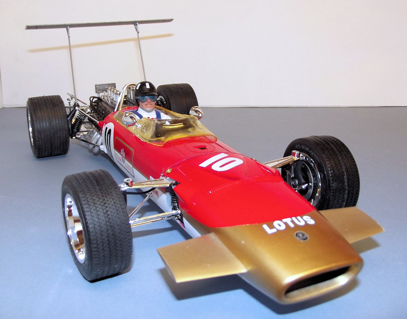
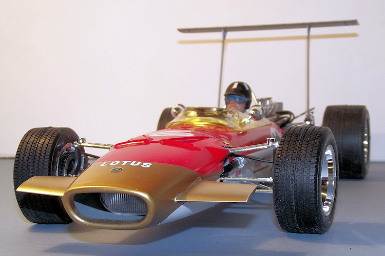
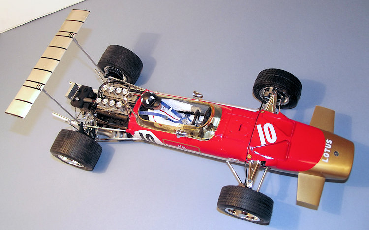
Tamiya 1/12 Lotus 49B
| KIT #: | 12053 |
| PRICE: | £68-00 from an internet vendor |
| DECALS: | Two options |
| REVIEWER: | Frank Reynolds |
| NOTES: | Use rattle cans and the price jumps |
| HISTORY |
This is all about 1968 and a trip down memory lane in so many ways.
In the 1960s the likes of Nitto, Nichimo, Midori and Tamiya released motorised kits of cars, aircraft and armour to an increasingly intrigued world market. Many were toy-like and compromised in design by the need to incorporate electric motors, gearboxes and dry batteries but the standard of moulding and external details made the more established Western manufacturers take notice. Tamiya soon established a reputation for beautifully engineered high quality kits at premium prices.
In 1968 I was 19 years old, the Beatles were singing Hey Jude and the Rolling Stones of Jumping Jack Flash. The British military were in the final stages of flight trials to introduce the F-4 Phantom to Royal Navy and Royal Air Force service. The siege of Khe Sanh occurred in Vietnam. In the second year of paid internship training as a real estate appraiser in the UK there was no way I could afford one of the fabulous Tamiya 1:12 scale cars, since they cost about a week’s pay.
 In that same year a dramatic change occurred in
the World of Formula 1 race cars when the FIA ( The International Automobile
Federation) changed its regulations to permit widespread commercial sponsorship
and the South African Grand Prix saw the Lotus 49B appear on the colours of the
John Player Tobacco Company’s Gold Leaf cigarette brand. The sensational new
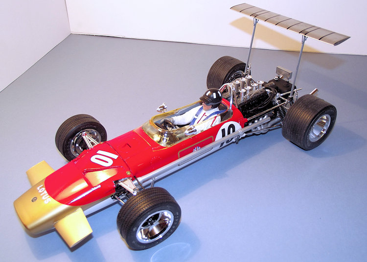
colours coincided with sensational new technology, with the car displaying a
frame mounted wing over the rear suspension to increase down force and traction;
during the season this innovation would be teamed with front wings to define a
race car configuration that is still familiar today. The Lotus 49s were fitted
with a new engine, the Cosworth DFV that would attain legendary status in
motorsport, to continue in developed form into the 1980s. The V8 engine was
capable of producing over 400bhp and its Double Four Valve arrangement provided
its distinctive name.
In that same year a dramatic change occurred in
the World of Formula 1 race cars when the FIA ( The International Automobile
Federation) changed its regulations to permit widespread commercial sponsorship
and the South African Grand Prix saw the Lotus 49B appear on the colours of the
John Player Tobacco Company’s Gold Leaf cigarette brand. The sensational new
colours coincided with sensational new technology, with the car displaying a
frame mounted wing over the rear suspension to increase down force and traction;
during the season this innovation would be teamed with front wings to define a
race car configuration that is still familiar today. The Lotus 49s were fitted
with a new engine, the Cosworth DFV that would attain legendary status in
motorsport, to continue in developed form into the 1980s. The V8 engine was
capable of producing over 400bhp and its Double Four Valve arrangement provided
its distinctive name.
The Lotus team was already well established in Grand Prix, but suffered a massive blow in April of 1968 when their star driver, World Champion Jim Clark, was killed at Hockenheim in Germany. His team mate Graham Hill battled on throughout the season to take the World title.
So the 1968 Lotus was a revolutionary world-beating car, with a brilliant engine, startling new technology and a stunning colour scheme. Tamiya lost little time in modifying their existing kit of the earlier Lotus 49 into the new wonder of the auto world. But the price of this magical piece of the mould makers’ art always seemed to be just ahead of what I could afford.
Which is why I had to wait over 45 years to enjoy Tamiya’s re-release of the fabled Gold Leaf Team Lotus 49B.
| THE KIT |
In its original release Tamiya intended that the
car should be motorised – a tall order since the suspension units were
relatively fragile and it would have taken a brave builder to free-run a
completed car over the living room carpet. The interior was also compromised to
provide room for the battery holder, resulting on t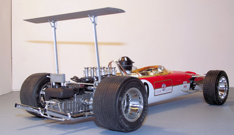 he driver’s cockpit being
shortened with no room for a foot well. In the 21st century release
the motorisation parts have thankfully been omitted.
he driver’s cockpit being
shortened with no room for a foot well. In the 21st century release
the motorisation parts have thankfully been omitted.
Presented in Tamiya’s usual high quality stout box, the parts are luxuriously packed with each colour of parts frame separately bagged and accessories both bagged and boxed. There are twelve parts frames, moulded variously in white, gunmetal, black, grey, one tinted yellow for the transparencies , while two have the mixed blessing of a high gloss vacuum plated chrome finish. There is a sheet of sharply printed decals which include race numbers and instrument faces, printed paint masks, self-adhesive die cut seat belts and a large frame of etched stainless steel. There is a set of turned alloy engine intake trumpets and a separate bag of vinyl tubing, cables, screws and springs. Finally, four large rubber tyres with a tread pattern typical of GP cars of the period. Truly a multimedia package.
Examination of the parts revealed slightly ragged edges to some of the major body components, suggesting mould wear. Perhaps the biggest annoyance was some obvious join lines on the parts frames that had been treated to the “chroming” process. These join could not be removed without damaging the shiny surface, so you have to live with the blemishes or completely refinish the plated parts.
| CONSTRUCTION |
A study of the instructions reveals that a very careful build is required. The suspension is set up in such a way that it must be assembled with working units throughout, since it will only settle on its springs right at the end of the build when the wheels are added; so great accuracy is needed. It is also necessary to establish where areas of the “chrome “ plating have to be scraped away with the tip of a scalpel blade to ensure that the glued joints are strong enough.
There is some scope to build sub-assemblies but I settled for trusting Mr Tamiya and generally following the assembly sequence set out in the instructions. The sequence of painting was varied as discussed below. In aiming for a straight from the box build I elected to use the Tamiya recommended rattle cans, four in all, which led to a paint bill of a little over £25-00.
 I am not a great fan of vacuum plating. I do not
know of any way to satisfactorily touch in the areas of raw plastic that are
exposed when parts are cut from the frame, nor can I refinish any gaps that
might have to be filled. I did consider stripping the plated parts and
experimented with offcuts from the parts frames to see if any of the
internet-recommended methods such as applying oven cleaner, or household bleach
might yield any bare plastic that might be conventionally painted, but I could
not get the plating to part company with the plastic, and I settled for what was
an offer in the box with the single exception detailed below.
I am not a great fan of vacuum plating. I do not
know of any way to satisfactorily touch in the areas of raw plastic that are
exposed when parts are cut from the frame, nor can I refinish any gaps that
might have to be filled. I did consider stripping the plated parts and
experimented with offcuts from the parts frames to see if any of the
internet-recommended methods such as applying oven cleaner, or household bleach
might yield any bare plastic that might be conventionally painted, but I could
not get the plating to part company with the plastic, and I settled for what was
an offer in the box with the single exception detailed below.
A race car of the period consists of a central pod that holds the driver, a nose that encompasses the front suspension and an engine to the rear that also supports the rear suspension. Stage 1 of construction deals with that central pod, to which all other main units are attached. The pod is moulded in two halves split lengthways with a front and rear bulkhead. Stage 2 adds an internal cockpit tub that provides the driver’s seat and side mounted gear change. The two halves of the pod were assembled, trapping a floor mounted hatch for the now-redundant battery box of the original. Front and rear bulkheads were glued in place and two small metal brackets were superglued onto the front bulkhead to provide alignment for screw-fixing the nose cowling later.
At this stage it was a major culture shock for a dyed in the wool aircraft modeller to have to consider painting and finishing of the body work. Since the paint job also involved the nose fairing it seemed logical to bring this into the paint shop at this stage, rather than at step 30 as recommended in the instruction book.
| COLORS & MARKINGS |
The body parts were washed, cleaned and allowed to dry and primed overall with Tamiya White Fine Surface primer applied from a rattle can. When dry this was buffed with an extra fine sanding stick and a second coat of the white applied. The white primer was sufficiently dense and smooth to serve as a finishing coat, so the exterior was temporarily masked off while the front and rear bulkheads and the tub interior were sprayed with Tamiya TS-32 Haze Grey.
The paint masks provided are a self-adhesive kabuki-type material and need to be cut out with a scalpel. Tamiya TS-8 Italian Red was sprayed from a rattle can, then buffed with a sanding stick. Two small insert panels to the front and rear of the cockpit opening needed to be sprayed red at this point. Finally the second set of masks was applied and the nose trim of Tamiya TS-21 Gold sprayed on.
Masking removed, small areas were touched in with paint decanted from the rattle cans and the bodywork left for a couple of days for the paint to harden after which it received two brushed coats of Future/Klear floor polish as preparation for the decals. Two decal choices are provided, essentially differing only in race numbers according to whether the car should have a rear wing only or an additional one over the front suspension.
The decals, although thick, reacted well to Micro Sol and Micro Set and were quite straightforward to complete, providing race numbers and some tiny sponsorship stickers. The Team Lotus decals on the body sides rather coyly omit the Gold Leaf logo of the John Player tobacco company. (Let us be gracious and assume that the omission is for licensing and copyright reasons.) A Web search revealed that full text decals are available in the after market but with the budget already running at a highish level I settled for the kit’s offering.
The painted and decalled body work then received two further brushed coats of Future/Klear to seal the decals and provide a suitably shiny finish. Now at this stage with my MM articles it is customary to add a conclusion and sign off. Not so in this case, with another 31 stages of construction to go.
| THE REST OF THE BUILD |
I covered my work area with a triple layer of good quality writing paper, to provide a cushion for the painted bodywork during the remainder of the build. The sides of the cockpit were masked off and the driver’s seat airbrush painted in Tamiya XF-1 Black, then the body set aside while attention turned to the front suspension.
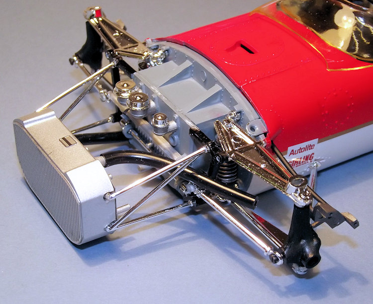 Steps 3 to 8 of the instructions deal with
building the front end. Slow and steady is the watchword, since much of the
front suspension is a snap fit and the various linkages, struts and suspension
arms must not be glued. Most of the pivots and swivels rely on the builder
pressing a “C” shaped linkage onto a plastic pin and I found it best to use fine
nose tweezers to squeeze the parts together rather than snapping them in place.
Other than the plated parts, the plastic components were airbrushed in Tamiya
Acrylics to match the base colour of the parts frames in Matt Black, Gunmetal or
Aluminium as required. The horizontal upper and lower suspension arms click
together in logical fashion if you follow the instructions, but before
committing to assembly each dry joint and swivel pin has to be checked to ensure
that there are no mould lines or ragged edges that could foul the free movement
of the parts. The lower arms are fitted to the body first, then the outer
uprights, fitted with brake calipers, are clicked into place on the lower arms.
Three hands or more are required for the next stage where the upper arms click
into place while trapping the front shocks that are fitted with a metal coil
spring. These sub-assemblies tend to flop around alarmingly but eventually with
persistence and many coffee breaks the front suspension was locked into place by
a space frame and bulkhead. Soft vinyl brake hoses are provided to connect the
calipers to small adjacent holes in the bodywork and the instructions provide a
cutting guide. A steering rack slips into loops on the sub frame and the
extended steering arms linked to pins on the front uprights. A metal shaft is
provided for the steering column but I omitted the pinion gear from the end of
the shaft so that I could juggle the steering wheel into position at the next
stage.
Steps 3 to 8 of the instructions deal with
building the front end. Slow and steady is the watchword, since much of the
front suspension is a snap fit and the various linkages, struts and suspension
arms must not be glued. Most of the pivots and swivels rely on the builder
pressing a “C” shaped linkage onto a plastic pin and I found it best to use fine
nose tweezers to squeeze the parts together rather than snapping them in place.
Other than the plated parts, the plastic components were airbrushed in Tamiya
Acrylics to match the base colour of the parts frames in Matt Black, Gunmetal or
Aluminium as required. The horizontal upper and lower suspension arms click
together in logical fashion if you follow the instructions, but before
committing to assembly each dry joint and swivel pin has to be checked to ensure
that there are no mould lines or ragged edges that could foul the free movement
of the parts. The lower arms are fitted to the body first, then the outer
uprights, fitted with brake calipers, are clicked into place on the lower arms.
Three hands or more are required for the next stage where the upper arms click
into place while trapping the front shocks that are fitted with a metal coil
spring. These sub-assemblies tend to flop around alarmingly but eventually with
persistence and many coffee breaks the front suspension was locked into place by
a space frame and bulkhead. Soft vinyl brake hoses are provided to connect the
calipers to small adjacent holes in the bodywork and the instructions provide a
cutting guide. A steering rack slips into loops on the sub frame and the
extended steering arms linked to pins on the front uprights. A metal shaft is
provided for the steering column but I omitted the pinion gear from the end of
the shaft so that I could juggle the steering wheel into position at the next
stage.
Build stages 9 through 14 provided a welcome break for the mechanical side of the build and concentrate on the driver. Consisting of a weighty one –piece solid moulding for the truncated legs, the body, head and helmet; adding the two arms and the helmet peak completed assembly of the figure. Tamiya’s instructions suggest that the figure’s arms should be added after the seat harness is installed and as the figure is settled around the steering wheel, but I could see no way of filling the shoulder joints when using this method so the arms went straight on. The figure has shallow engraved lines on the sleeves and shoulders which line up to define a red stripe on the overalls.
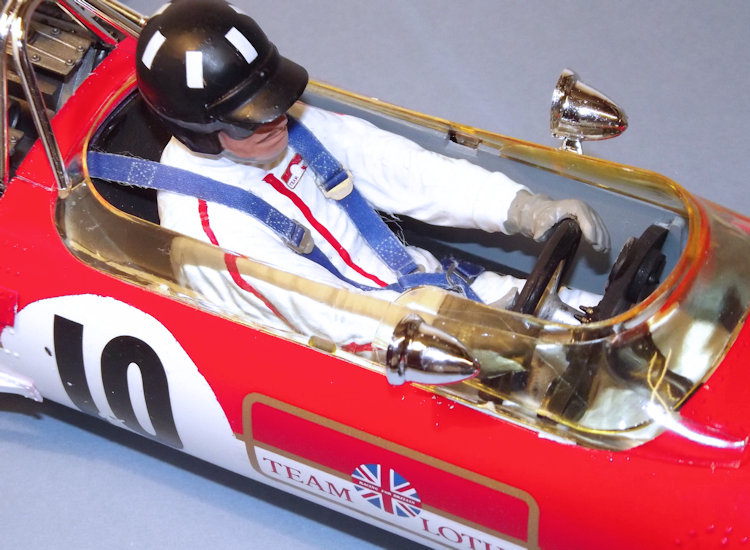 I am certainly no figure painter and it was a
relief to find that the driver’s face and head are obscured by goggles and a
helmet. The figure was cleaned up with a smear of Revell Plasto filler at the
shoulder joints and a shallow mould line running up the arms and legs was gently
removed with a fresh scalpel blade. The whole figure then received two coats of
Tamiya Fine White Primer applied from a rattle can. When dry the narrow red
stripes on the overalls were picked out in Tamiya XF-7 Red applied with a small
brush. The driver’s helmet was painted Black and his scarf, gloves and goggles
in medium grey. The face was simply brush painted in Citadel acrylic Cadian
Fleshtone worked back and forth over the white undercoat with a small brush.
This provides some contrast between the creases and raised areas of the face. I
decided that I would not attempt to emulate a skilled figure painter and leave
it at that, relying on the natural creases and folds in the large scale
mouldings to provide some shadows. The goggles had the glazed area painted
medium grey with an overlay of X-23 Clear Blue to provide a hint of a tint .
Finally the moustache was carefully picked out in medium brown and a small
sponsor’s decal was applied to the upper chest. Some offcuts of white decal were
applied to the helmet in the style of that worn by that British sporting hero of
the period – Graham Hill. It is worth pointing out that the driver bears a close
resemblance to Hill but the instructions do not identify him as such.
I am certainly no figure painter and it was a
relief to find that the driver’s face and head are obscured by goggles and a
helmet. The figure was cleaned up with a smear of Revell Plasto filler at the
shoulder joints and a shallow mould line running up the arms and legs was gently
removed with a fresh scalpel blade. The whole figure then received two coats of
Tamiya Fine White Primer applied from a rattle can. When dry the narrow red
stripes on the overalls were picked out in Tamiya XF-7 Red applied with a small
brush. The driver’s helmet was painted Black and his scarf, gloves and goggles
in medium grey. The face was simply brush painted in Citadel acrylic Cadian
Fleshtone worked back and forth over the white undercoat with a small brush.
This provides some contrast between the creases and raised areas of the face. I
decided that I would not attempt to emulate a skilled figure painter and leave
it at that, relying on the natural creases and folds in the large scale
mouldings to provide some shadows. The goggles had the glazed area painted
medium grey with an overlay of X-23 Clear Blue to provide a hint of a tint .
Finally the moustache was carefully picked out in medium brown and a small
sponsor’s decal was applied to the upper chest. Some offcuts of white decal were
applied to the helmet in the style of that worn by that British sporting hero of
the period – Graham Hill. It is worth pointing out that the driver bears a close
resemblance to Hill but the instructions do not identify him as such.
Four distinct build stages are devoted to the drive’s safety harness. The belts are beautifully presented as pre-coloured, die cut, self-adhesive fabric sections with well-produced etched stainless steel buckles and accessories. The etched parts were carefully cut from the frame and any sharp tangs smoothed out with a steel file. The central quick release buckle is formed from nine layers of etch, gently tacked together with cyano glue. The seat belts build up steadily and the instructions give clear guidance on how to thread them onto the various buckles and loops. I found it best to do them one pair at a time spread over several modelling sessions, the only pitfall being the fact that the rear face of each belt is self-adhesive and it is best to ensure that the belts only fold back on themselves when it is the builder’s choice. Suitably draped over and around the figure, they certainly brought the model to life. Not convinced of the belts’ adhesive qualities long term I smeared some dabs of epoxy resin under the belts in strategic locations on the driver’s overalls. The whole figure was airbrushed with two thin coats of Xtracrylix flat varnish.
 Attention now turned to the minimalist instrument
panel. Consisting of just five dials, Tamiya offers a choice of decals or etch
instrument faces. I settled for etch and the five discs were superglued onto the
Matt Black panel. When dry the dials were coated with Future/Klear floor polish
to give a hint of glazing. The steering wheel was painted matt black with
aluminium spokes and the wheel slipped onto the metal steering column which was
then threaded through the instrument panel. This wheel was then forced into the
hands of the driver and the driver/steering combination juggled into place in
the cockpit. The absence of the pinion gear allowed enough free play in the
assembly to get the column to line up though the front bulkhead and after a
couple of dry runs the driver was seated onto a few blobs of epoxy and the
instrument panel glued into steps in the cockpit sides. The shoulder straps of
the seat harness were pulled over the rear edge of the cockpit tub, again
secured with a dab of epoxy. The two small inserts that had been previously
painted were added to the front and rear of the cockpit opening, ready for
attachment of the windshield.
Attention now turned to the minimalist instrument
panel. Consisting of just five dials, Tamiya offers a choice of decals or etch
instrument faces. I settled for etch and the five discs were superglued onto the
Matt Black panel. When dry the dials were coated with Future/Klear floor polish
to give a hint of glazing. The steering wheel was painted matt black with
aluminium spokes and the wheel slipped onto the metal steering column which was
then threaded through the instrument panel. This wheel was then forced into the
hands of the driver and the driver/steering combination juggled into place in
the cockpit. The absence of the pinion gear allowed enough free play in the
assembly to get the column to line up though the front bulkhead and after a
couple of dry runs the driver was seated onto a few blobs of epoxy and the
instrument panel glued into steps in the cockpit sides. The shoulder straps of
the seat harness were pulled over the rear edge of the cockpit tub, again
secured with a dab of epoxy. The two small inserts that had been previously
painted were added to the front and rear of the cockpit opening, ready for
attachment of the windshield.
The yellow tinted windshield components were the most disappointing aspect of the kit, being slightly warped and twisted and with ragged edges to the mouldings. They cleaned up a bit after attention with a sanding stick and the alignment improved when the prominent tabs were glued to the cockpit edges but some distortion remains. The plated roll bar was installed to complete construction of the centre section.
At step 15, construction reverted to the nose area and the installation of the cooling system. The prominent radiator was sprayed flat aluminium and detailed with large etched grilles to the front and rear faces, secured with a smear of cyano glue. Secured to the front bulkhead with “N” struts, the radiator unit was connected to the bulkhead with a length of rubber hose while a second section was led through the suspension unit, to be connected later in the build. Three plated master cylinders, for brake and transmission hydraulics were fitted to the front bulkhead and the nose cone trial fitted to ensure that all of these assemblies tucked in comfortably.
The previous advance study of the instructions revealed that Tamiya intends the builder to assemble the complete engine unit, its accessories, cables, pipes and exhaust system and then fix the whole to the rear of the cockpit via two sliding hooks and two plastic pins. This joint is done blind due to the bulk of the engine and it is so fundamental to the alignment of the whole car that I chose to fix the bare engine block onto the tub and then hang all the extras on later.
 The basic engine was assembled as a block with the
“V” configuration cylinder heads painted gunmetal and the head plates for the
spark plugs painted matt black. A space frame was attached to the rear of the
engine to support the coolant filler reservoir, which was connected to the block
by two short lengths of rubber hose. Again to the rear, the gear box was built
up from two sides, a rear and top plate and assembled to trap a rotating
connecting tube for the rear stub axles. This presumably substitutes for the
small metal gearbox that would have been installed in the original issue of the
kit. The water and oil pumps were glued to the outer lower sides of the engine
block.
The basic engine was assembled as a block with the
“V” configuration cylinder heads painted gunmetal and the head plates for the
spark plugs painted matt black. A space frame was attached to the rear of the
engine to support the coolant filler reservoir, which was connected to the block
by two short lengths of rubber hose. Again to the rear, the gear box was built
up from two sides, a rear and top plate and assembled to trap a rotating
connecting tube for the rear stub axles. This presumably substitutes for the
small metal gearbox that would have been installed in the original issue of the
kit. The water and oil pumps were glued to the outer lower sides of the engine
block.
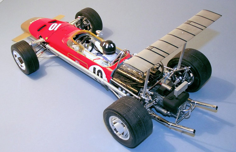
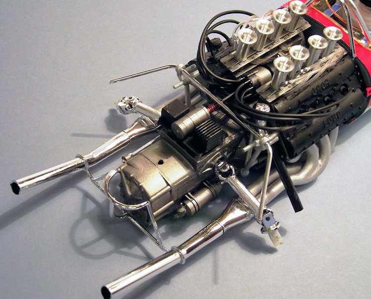
Then came the most challenging part of the build. The distributor is intended to be snugly fitted into the trench on the top of the engine, between the two banks of cylinders. This is made up of three plastic sections and totals about 25mm long. At one end are nine small plastic pins to carry the vinyl tubing (70mm lengths) to connect to the spark plugs and coil. At the other end, eight small plastic pins carry the clear plastic fuel tubing (60mm lengths) to the intake trumpets. The tubing must be fitted first and the distributor unit then guided into the tight space. After a number of trial fits I concluded that it might be useful to take advice from anyone who has experience of trying to cram a set of bagpipes and an angry octopus simultaneously into the same suitcase. The various tubes took it in turn to fall off and if the assembly was pushed too hard into place, then a twisted tube would cause the plastic pins to break. Eventually I replaced all of the pins for the clear tubing with hooks of brass wire superglued into carefully drilled holes. Most of the tubes now have a smear of superglue over the joint. I am aware that superglue will not fix vinyl, but at least it inhibits the tendency for the tubes to slip off the plastic pins.
The black plug leads were temporarily tied off with cotton thread in a bundle and draped over the rear of the engine, while the transparent fuel lines were temporarily tied into pairs. The induction system sits on two groups of four inlet tubes just inside the cylinder banks. Four plastic inlet pipes/injectors each side have turned metal intake trumpets superglued around them. Significant omissions from the kit are the prominent mushroom-domed inlet grilles over the inlets of the eight intake trumpets. They are quite obvious on photos of the real thing.
The clear fuel pipes have to be carefully guided under the induction system as it is glued in place, then the pipes push fitted onto small pins to secure them at the base of the trumpets. The plug leads were brought round to slip onto small raised pins on the spark plugs and although Tamiya calls out for the leads to be the same length, each opposite pair was trimmed according to the distance from the distributor. I did my best to follow the trail of each cable and pipe according to the instructions, but if I have wired the firing order incorrectly I am past caring. I believe that it took me a week of interrupted modelling sessions to complete this cat’s cradle. I did consider permanently tying off the bundles of tubing to look neater, but the risk of causing some of them to pull loose was enough to kill that idea. In spite of these trials, it was surprisingly satisfying to see the finished result.
By now it was stage 23 of the instructions and the installation of the sinuous 4 into 2 into 1 exhaust system. The two pairs of manifold units for each side of the engine had such bad mould lines that they could not be overlooked. It took a good deal of sanding and scraping to remove the plating from every nook and cranny of the mouldings and clean them up before they could be sprayed Flat Aluminium. The remaining pipes were left plated since their brightwork provided a distinctive contrast. The paired manifolds plugged neatly into large sockets in the engine blocks and each pair led via a connector to the single end pipes, which are in turn aligned by a space frame glued to the back of the gear box. All of the exhaust pipe joints were fixed using slow setting tube glue giving plenty of time to tweak the alignment of the whole system before the glue set.
 After a couple of days to let everything settle,
it was time to tackle the rear suspension. The two rear drive shafts each
consist of three sections linked by universal joints. Each shaft section was
moulded split lengthways and the halves joined with light smears of thick tube
cement that resists running into unwanted areas. As the halves are closed up the
cross-shaped pivots are trapped in place, providing a realistically articulated
joint. The inner stubs of the drive shafts were glued into the rotating axle
joiner previously buried in the gearbox.
After a couple of days to let everything settle,
it was time to tackle the rear suspension. The two rear drive shafts each
consist of three sections linked by universal joints. Each shaft section was
moulded split lengthways and the halves joined with light smears of thick tube
cement that resists running into unwanted areas. As the halves are closed up the
cross-shaped pivots are trapped in place, providing a realistically articulated
joint. The inner stubs of the drive shafts were glued into the rotating axle
joiner previously buried in the gearbox.
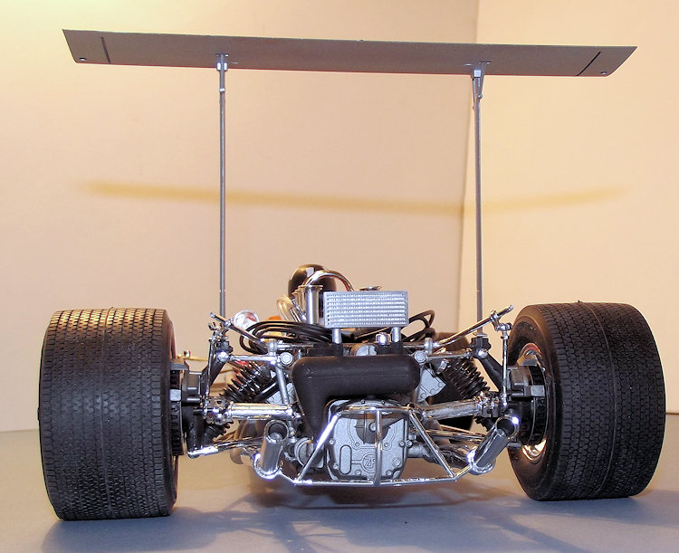
The rear suspension was treated similarly to the front; each side consisting of a vertical upright to which the upper and lower wishbones were clipped. These were followed by the brake calipers and the shocks with their external coil springs. These fragile units had to be carefully lifted, levered and clipped into place, with the forward lever arms slid into holes in the main bodywork, then covered with small retaining plates. Finally the steadying linkages were clipped onto their pins on the engine sub frame. Once again it seemed that a minimum of three hands would make life so much easier.
The oil tank and its prominent cooler were painted gunmetal and etched grilles added to the front and rear face of the cooler, the glued to a location hole atop the gearbox, looking for all the World as though the designer had just thrown it to fit wherever it landed.
The wheels consist of inner and outer halves. Fitted to the inside axle, the disc brakes came as two plastic discs, each faced with a disc of etched stainless steel. The parts are handed and care is needed to line them up correctly. I succeeded at the second attempt. Next the tyres were stretched around the wheels. As supplied they have a prominent mould seam running down the centre of each tread, but I did not want a weathered look so sanding this down was not an option. I reduced it as much as I could by shaving down the line with a brand new scalpel blade.
The wheels were secured by small plastic pins fed in from the inner face of the suspension uprights and glued into the stub axles on the wheel hubs. The long coolant pipe to the left side of the cockpit was painted Flat Aluminium, then linked to the rubber hose from the front radiator and the rear hose from the engine block. The nose cone was pushed into place and secured with two brass bolts onto the edge of the front bulkhead. Finally the rear wing was assembled by gluing the two support struts in place, painted Flat Aluminium and the kit decal for the striped upper surface installed. At stage 33, just two dabs of cement secured the rear wing to sockets in the rear suspension and the 49 was ready to take its place on the grid. On completion I found that the suspension works – just. If gently compressed it creaks and groans its way up and down, but there is no way this race car is ever going to be pushed across the carpet.
| CONCLUSIONS |
They say that you should be cautious about meeting your heroes, especially when they are older, just in case you are disappointed.
As an example of cutting edge late 1960s kit
technology it is excellent and a reminder of just how good Tamiya were (and
remain). As a scale model it has some limitations since some of the wise men of
the web point out that the 49B was modified so much in the course of the 1968
season that the kit as offered is no
 more than an approximation, a bit of a bitsa.
As a 21st century kit, some limitations are apparent, with a need to clean up mould lines as the result of apparent wear in the tooling that is into its sixth decade. The updated parts are a mixed success in my opinion. The seat belts with etched buckles are a significant improvement. The use of etch for the brake discs and radiator grilles is a good feature. However I feel that the turned metal intake trumpets offer little over the plated plastic versions that are unused on the parts frame, since there are so many other components in the over-shiny “chrome” that the impact of the real metal parts is diminished. With the availability of sophisticated metallic paint finishes in the 21st century I wonder whether this kit would be better without the plating at all. Some say that the finished car is toy-like. I am inclined to agree but it is still a great toy.
The Tamiya 1:12 scale Lotus 49B delivered what I had asked of it, despite the challenges. As a trip down memory lane it was thoroughly satisfying and a pleasure to build.
| REFERENCES |
The Internet - and an increasingly hazy memory.
February 2016
Copyright ModelingMadness.com
If you would like your product reviewed fairly and fairly quickly, please contact the editor or see other details in the Note to Contributors.