|
KIT # |
496 |
|
PRICE: |
Probably around $.29 when new |
|
DECALS: |
One aircraft |
|
REVIEW : |
|
|
NOTES: |
` |
"SING THE BLUES IN SOLO"
|
HISTORY |
The Chance Vought F7U Cutlass was the most radical fighter design ever to achieve fleet service. The bold design of the Cutlass gave the Navy a pioneer airframe which was to test and develop many systems that are still in use today.
The F7U was the first tailless airplane to go into production in the United States and the first jet fighter in the U.S. designed from the outset with afterburners. The Cutlass was also the Navy's first swept wing jet, its first with steerable nose wheels and an irreversible power control system.
Design for the Cutlass started in June 1945, and the tailless configuration was developed in an attempt to solve the compressibility problems then being encountered by such planes as the P-47 and F4U. These aircraft were experiencing the compressibility phenomenon at around Mach .75 and since the F7U was expected to operate in the neighborhood of Mach .9+, a solution was necessary. It was known that at this high speed the downwash on the horizontal tail was causing the nose to tuck under. Once this started the stick forces would become too great for the pilots to handle. Since it was not possible to effect a trim change large enough to give a negative lift coefficient, Vought decided to solve the problem by eliminating the horizontal stabilizer.
 The Navy opened a 1945 fighter competition for a fighter
capable of operating at 40,000 feet and 600 mph. In competition with twelve
different designs by six companies, the Vought V-346A was chosen the winner on
June 25, 1946, and designated XF7U-1.
The Navy opened a 1945 fighter competition for a fighter
capable of operating at 40,000 feet and 600 mph. In competition with twelve
different designs by six companies, the Vought V-346A was chosen the winner on
June 25, 1946, and designated XF7U-1.
The Navy described the XF7U-1 as an experimental, tailless fighter designed for carrier operations and equipped with two 24C turbojet engines. The principal features included sweptback (35 degrees) wings of low aspect ratio, tricycle landing gear, pressurized cockpit, and a fixed gun armament of four 20mm cannon. The engine specification was changed to two Westinghouse J34-WE-32 turbojets by the time of the initial flight.
The folding wings were fitted with "ailevators" which combined the function of elevators and ailerons. Since there were no landing flaps, leading edge slats provided the low speed characteristics required for carrier landings. Initially four speed brakes were installed in the XF7U-1. Two were of the clamshell variety mounted on the trailing edge of each wing between the fuselage and vertical tail, while the other two were located under the leading edge of the intake ducts. The latter proved ineffective and were removed.
The XF7U-1 flew for the first time on September 29, 1948 and without the aid of afterburners. This flight and those to follow were sufficiently promising for the Navy to place an order for 14 production F7U-1 aircraft.
The fourteen production F7U-1s were never put into squadron service. Two F7U-1s, 124426 and 124427, were assigned to the Blue Angels for use during their 1952 shows. The Blues were flying F9F-5 Panthers at the time and the two Cutlasses were mainly to be used as solo performers. The two pilots, Lt. Cdr. Edward L. Feightner and Lt. Harding C. MacKnight only had their birds for a short time before they were retired due to parts shortages. Other F7U-1s were used by the advanced training command until they too ran out of parts. After the -1s were no longer flyable, some were relegated to the Naval Air Technical Training Command, where they were used as jet maintenance trainers.
In retrospect, this unorthodox design, which took ten years to reach service squadrons in the form of the F7U-3, proved too complicated and, more importantly, did not offer the performance and dependability that its more conservative contemporaries exhibited. Nevertheless, such forward looking aircraft as the F7U laid the basis for more successful twin-tailed aircraft of today, such as the Grumman F-14 Tomcat and the McDonnell Douglas F/A-18 Hornet. It could truly be called the Studebaker of jet fighter designs coming out of the late 1940s and early 1950s, too far ahead in the design department for the technology of the time.
SPECIFICATIONS: CHANCE VOUGHT F7U-1 CUTLASS
 About the aircraft modeled:
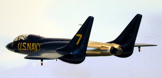
Although the Navy's Blue Angels Precision Aerobatic Team utilized Grumman F9F-5 Panthers at the time, two Vought F7U-1 Cutlass aircraft, 124426 and 124427, were employed for individual solo performances. They flew for only two shows of the 1952 season (Glenview, Illinois and Detroit, Michigan), but were forced to be grounded for lack of spare parts.
There were only 14 production "dash one's" made and with Vought having introduced the F7U-3, a much heavier aircraft and totally different in construction though still baring the appearance of the -1, parts were not available for the former models introduced in 1950.
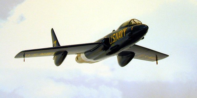
The subject I have modeled (Bureau No. 124426), left the Vought factory in late 1951 and was assigned to the U.S. Navy Blue Angels as an upcoming solo performer during the 1952 season. This aircraft flown by Lt. Hardin C. MacKnight, along with another F7U-1 flown by Lt. Cdr. Edward L. Feightner, excited audiences during their two solo performances, particularly with their extremely loud afterburners, something that was fairly new to the civilian in 1952.
When I saw a picture of the two Cutlasses flying over the Dallas factory, in color no less, I just had to build a Cutlass for my Blue Angel collection, of which this is the fourth model completed.
The problem I first encountered was finding a model of an F7U-1 Cutlass. There are plenty of F7U-3s on the market by Fujimi, but where would I find a "dash one". The help came from a model collector in Duxbury, Massachusetts. I purchased an old Aurora kit (Kit No. 496) from this kind gentleman and proceeded to start the kit upon its arrival.
|
CONSTRUCTION |
The Cockpit
Needless to say, there was no cockpit in the kit. As a matter of fact, the cockpit area wasn't even open. There was a generic pilot's head and upper coaming area molded into each fuselage half.
I cut out the cockpit opening in the kit and scratch-built a cockpit using a Matchbox F9F-5 cockpit as a reference to go by. I used sheet styrene for the cockpit, instrument panel, and instrument panel shroud. The seat was scratch-built out of sheet styrene using photos I had of F7U-1 seats, which were made by Vought themselves. The pilot was rifled from the said mentioned Matchbox kit.
I used various decals for the cockpit sides and the instrument panel, these I took from surplus decal stock. Radio equipment and other boxes were depicted using auto striping tape and painted with a clear flat finish (I like to brush paint Testors Dullcote, as it dries almost immediately).
I have had other modelers tell me that the interior was a neutral grey, but in the photo the ejection seat is more of a medium green, so I painted the interior with Model Master Medium Green. The instrument panel, instrument panel shroud, and cockpit sides from canopy closure line to canopy were painted flat black.
 The pilot was painted with Polly S and Tamiya acrylics and
given a black wash. The helmet was painted a light blue that I mixed to match
the photo I have and goggles were painted black. After the paint dried I coated
the helmet and goggles with Johnson's FUTURE and applied a small strip of sanded
black auto striping tape for the goggles strap.
The pilot was painted with Polly S and Tamiya acrylics and
given a black wash. The helmet was painted a light blue that I mixed to match
the photo I have and goggles were painted black. After the paint dried I coated
the helmet and goggles with Johnson's FUTURE and applied a small strip of sanded
black auto striping tape for the goggles strap.
The seat was painted medium green, with the headrest being painted Tamiya Hull Red and given a light brushing of skin oil to semi gloss it. Rudder pedals were simulated with two pieces of silver auto striping tape.
After I cemented the pilot to the seat, I attached two small strips of masking tape to the pilot and into two small slots that I had milled for the seat harness, these being painted olive drab. The cockpit was sit aside for the next adventure with this kit.
Fuselage and Wings
Discounting the landing gear pieces, which were not used, this kit had only 11 parts for the entire assembly. I proceeded to sand every piece in the kit into a smooth surface. Anyone who knows of these old kits can attest to the extent of overexposing the control surfaces and rivets. Fortunately this kit was molded with raised detail and it is much easier to sand raised detail smooth, then to have to fill and sand recessed detail. Something else I will have to give the kit maker of this day, the plastic is much more user-friendly to sandpaper then the plastic of today.
I was able to sand all the sections in two days and then proceeded to rescribe lines using photocopies of 1/72 scale plans that I had reduced from some 1/48 scale plans that I was able to locate. This was done by first scribing the lines for control surfaces, wing slats, landing gear doors, fuselage panels, and canopy closure with a curved blade in a hobby knife. After I had cut the lines, I then cut out the lines with a dentist's scraping tool, sanded to remove any plastic raised in the scribing and then washed the pieces to remove any skin oil or sanding grit.
I then drew my attention to the air intakes and made baffles for both. The inner air intake piece is actually three pieces of sheet plastic, one being shimmed against another so that the entire assembly will fit the inside of the fuselage, while looking right on the outside. The cannon gun ports were drilled out and filed. I scratch-built the exterior vents mounted just below and forward of the air intakes out of sheet styrene.
The vertical stabilizers were cemented to their proper wing halves, filled with gel type super glue, and sanded smooth. I used an accelerator here, as it made the cement more sandable and I was not too concerned about the bond (always check for air bubble pits when using an accelerator with this type of cement).
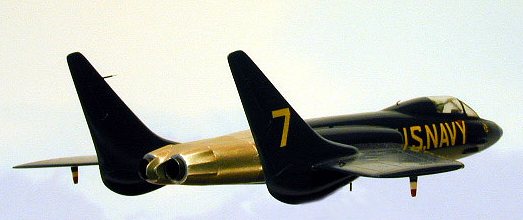
I removed the twin exhausts from the exhaust assembly and extended the rear section with two pieces of sheet styrene. Exhaust protective pieces were also constructed of sheet styrene, that I rolled with a piece of heated brass to get the curvature needed (tape the brass where you are going to handle it), and cemented to the exhaust assembly. Lastly two exhausts were cut from 1/4 inch aluminum rod, these being thinned on the exposed edge by using a cone-shaped cutting bit and cone-shaped sanding bit in a pin vise. These were painted gunmetal, with a little more black added, on the outside and Testors Jet Exhaust inside, then set aside for installation after the model was painted.
The exhaust assembly was cemented to the fuselage halves and the entire assembly was wet sanded to remove any abnormalities in the cemented joints. The wing/vertical stabilizer assemblies were now cemented to the fuselage assembly and this was also lightly filled and sanded.
 The canopy was useless in its molded form, but was useful in
supplying me with a start for a mold to stretch-form a new canopy out of clear
butyrate. I filled in the heavy molded separation line in the kit canopy with
gel type super glue and added three 2mm sections of sheet styrene to the bottom
of the front section. I then added strips of evergreen styrene and slowly built
up a curvature in the top of the canopy to match photos I had. After I achieved
a curvature to my liking, I filled in the strips liberally with super glue. I
then wet sanded the mold while constantly checking the fit and when the desired
shape was met, I polished the mold with two grades of Meguire's Mirror Glaze.
After I had polished the mold to my liking, I applied a coat of Johnson's
FUTURE, attached a piece of long sprue (4 inches will do) to the inside of the
mold, and filled the inside of the mold with epoxy to strengthen it during the
stretch-forming.
The canopy was useless in its molded form, but was useful in
supplying me with a start for a mold to stretch-form a new canopy out of clear
butyrate. I filled in the heavy molded separation line in the kit canopy with
gel type super glue and added three 2mm sections of sheet styrene to the bottom
of the front section. I then added strips of evergreen styrene and slowly built
up a curvature in the top of the canopy to match photos I had. After I achieved
a curvature to my liking, I filled in the strips liberally with super glue. I
then wet sanded the mold while constantly checking the fit and when the desired
shape was met, I polished the mold with two grades of Meguire's Mirror Glaze.
After I had polished the mold to my liking, I applied a coat of Johnson's
FUTURE, attached a piece of long sprue (4 inches will do) to the inside of the
mold, and filled the inside of the mold with epoxy to strengthen it during the
stretch-forming.
Since I have never got the hang of vacuforming anything with as much curvature as a canopy, I use the heating element of my old Mattel Vacuform Machine and when the plastic is properly heated I pull the heated butyrate up and insert my mold into the butyrate as far as it needs to go to get the shape I'm after.
I always make multiple pieces while I'm at it, as the canopies are very thin and easily miscued in cutting if one is not exceedingly careful. The down side to this is that any abnormality that exists on the mold will positively show through. If really makes one appreciate the trouble cottage industries go through making clear vacuform parts for modelers. After I had made the canopies, I chose the first one that was cut out correctly.
Activating rods for the rudder, trim tabs, and ailevators were constructed from 26 gauge wire and cemented into predrilled holes. Underwing blade antennas were cut from sheet styrene, painted, and set aside for assembly after the model was painted and decaled. Likewise the antenna on the underside fuselage was cut from 18 gauge wire, painted, and saved for installation later.
The small bent antenna on the canopy section was cut from .005 stainless steel wire, attached later, and painted after assembly. The pitot tube on the port vertical stabilizer was constructed from a 25 gauge hypodermic needle and stainless steel wire. The small bulge underneath the fuselage just ahead of the gun ports is nothing more than a drop of epoxy.
The framing on the canopy forward section was cut from sanded black auto striping tape after the canopy was installed and cleaned up. I used the kit nose piece after filling the attachment hole for the nose boom. (For some reason Aurora's kit showed an F7U-3 on the box art and the kit's raised molding outlined the rudders, ailevators, etc. of an XF7U-1.)
|
PAINT & DECALS |
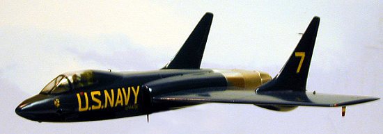
After the canopy was installed and masked, I primed the entire assembly in neutral grey primer. After this had dried for two days, I rubbed out the primer with an old undershirt , filled any abnormalities, and reprimed these areas. A day later I rubbed out the reprimed areas and airbrushed three coats of Model Master Blue Angel Blue and set the model aside for two weeks (its been very wet weather here).
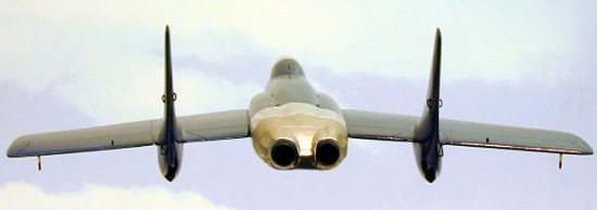
After the fortnight sabbatical, I polished the model with Meguire's Mirror Glaze #3 (their finest abrasive) and applied Bare-metal Foil to the three rear sections of the engine/exhaust assembly. The foil on the two rear sections was coated with Testors Dullcoat, as the photo I have shows this area as having a flat appearance and the forward section as being polished.
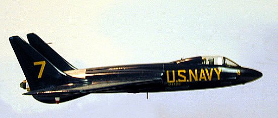
 The decals are a mish-mash from three separate decal sheets.
The number 7 on the vertical stabilizers used two different numbers, 1 and 2,
from SuperScale sheet 72-138. The bureau numbers were individually cut from
sheet 72-138; I had to invert four number 5s to get the number 2s I needed. The
underwing decals likewise came from SuperScale sheet 72-138. This is strictly
speculation on how the underwing motif looked as I have no drawing, photo, or
written authenticity as to how it looked. It just looked right to my eye and I
took artistic license on this one. The U.S. NAVY fuselage decals are from
SuperScale sheet 72-133. I wanted to use some I had left over from the Blue
Angels Bearcat I built, but they were not large enough. The ones I utilized are
correct in their length, but a little tall in their characters. The Blue Angels
logo decals are from the Matchbox F9F-4/5 kit.
The decals are a mish-mash from three separate decal sheets.
The number 7 on the vertical stabilizers used two different numbers, 1 and 2,
from SuperScale sheet 72-138. The bureau numbers were individually cut from
sheet 72-138; I had to invert four number 5s to get the number 2s I needed. The
underwing decals likewise came from SuperScale sheet 72-138. This is strictly
speculation on how the underwing motif looked as I have no drawing, photo, or
written authenticity as to how it looked. It just looked right to my eye and I
took artistic license on this one. The U.S. NAVY fuselage decals are from
SuperScale sheet 72-133. I wanted to use some I had left over from the Blue
Angels Bearcat I built, but they were not large enough. The ones I utilized are
correct in their length, but a little tall in their characters. The Blue Angels
logo decals are from the Matchbox F9F-4/5 kit.
When the decals had dried, I gently washed them to remove adhesive residue and coated all exterior surfaces, saving the flat black anti-glare panel and the rear exhaust assembly, with Johnson's FUTURE.
Wing navigation lights were cut out previously and replaced with drops of epoxy. After setting I painted the port wing light Tamiya Clear Red and the starboard light Tamiya Clear Blue.
|
REFERENCES |
COMBAT AIRCRAFT OF THE WORLD, George Rainbird Ltd., Marble Arch House, 44 Edgeware Road, London, W2, United Kingdom, 1969.
Ginter, Steve, CUTLASS: The Full Story Of The U.S. Navy's Most Unorthodox Fighter Of The Fifties, AIRPOWER, Volume 13, Number 6, November, 1983, Sentry Books, Inc. 10718 White Oak Ave., Granada Hills, CA 91344.
Gunston, Bill, The Encyclopedia of the World's COMBAT AIRCRAFT, Salamander Books Ltd., 52 James Street, London, W1, United Kingdom, 1976.
McGuire, Jim, "A Pictorial History of the Blue Angels", Squadron/Signal Publications, Inc., 1115 Crowley Drive, Carrollton, TX 75011, 1981.
Copyright ModelingMadness.com. All rights reserved. No reproduction in part or in whole without express permission.
If you would like your product reviewed fairly and fairly quickly, please contact the editor or see other details in the Note to Contributors.