Revell/Frog 1/72 Shackleton MR.3
| KIT #: | 04101 |
| PRICE: | $10.00 at the time |
| DECALS: | Two options |
| REVIEWER: | Torben Plesberg |
| NOTES: | Mild conversion |
| HISTORY |
I have already dealt with the development of the Shackleton in my review of the AEW 2 variant. In this round I will only deal with the MR 3 variant.
The Shackleton was designed to fulfil the following tasks:
Anti-submarine warfare
Maritime patrolling and reconnaissance
SAR missions
Troop transport (16 fully equipped troops)
Bombing missions
 The MR 3
was the most advanced variant of the Shackleton series. At an early design stage
it was known as the MR 2A. However, in the end it featured so many changes
compared to the MR2, that it was actually an entirely new aircraft, the
Shackleton MR 3. This fact might also be deduced from looking at the Avro type
numbers: The Shack MR 1s and MR 2s are known as Avro type 696, whereas the MR 3
is type 716.
The MR 3
was the most advanced variant of the Shackleton series. At an early design stage
it was known as the MR 2A. However, in the end it featured so many changes
compared to the MR2, that it was actually an entirely new aircraft, the
Shackleton MR 3. This fact might also be deduced from looking at the Avro type
numbers: The Shack MR 1s and MR 2s are known as Avro type 696, whereas the MR 3
is type 716.
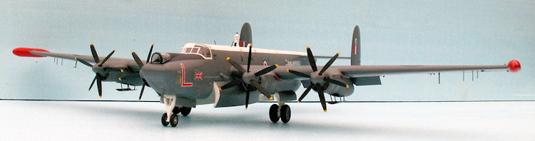
As the MR1 and MR2 variants did not quite meet the requirements for long range, Avro considered to make a new design with an increased load of fuel: 800 Imperial gallons. The redesign included new outer wings with increased area ailerons, large wing tip tanks, a strengthening of the wing to carry the extra weight of the fuel, a 5.2 feet longer fuselage, a new canopy with no framing in the sides, a new tail plane, and a tri-cycle undercarriage for better ground handling. The maximum permissible take-off weight did increase from 86.000 lbs. to 100.000 lbs. and the maximum allowed take off distance was 5250 feet to clear a 50 feet obstacle. However, in hot areas a take-off distance of 6300 feet was acceptable.
Due to the structural changes and changes of the equipment and interior lay out the empty weight of the MR 3 had increased by some 6.000 lbs. compared to the MR2. With a full load of fuel and weapons and SAR equipment, the Shack was getting rather heavy and even underpowered in hot areas.
As the production of the 34 airframes the RAF needed was at an end, and all of them upgraded to phase 1 standard, which mostly was a renewal of electronic equipment, another upgrading programme was already planned to make the Shacks as phase 2 aircraft. The most important difference between a phase 1 and a phase 2 aircraft, was the distinct Orange Harvest gear on the dorsal (that is from a modeler’s point of view of course) but the other changes of the equipment were not visible as seen from outside the aircraft, except for one small antenna or two. The phase 2 updating took about two months to complete.
The Orange Harvest was an S band and X band radar warning receiver, giving a directional bearing to surface ships and submarines, if they were transmitting radar emissions. It was a passive system, which did not betray the presence of the aircraft to its targets. It looked like a spark plug with a blue light in the top.
Already
before the phase 2 programme was finished, the next upgrading programme was
planned, the phase 3. Since the weight of the Shack had increased to 100.000
lbs., it was obvious that the aircraft needed more power for take-off –
especially in hot areas. A liquid- fueled rocket, the DH Super Sprite was
considered. This rocket had an output of 4200 lbs. of static thrust for 40
seconds. Because of its size and weigh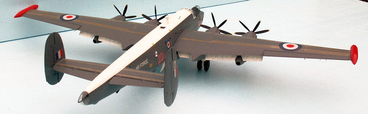 t
it could not be placed in the centerline of the aircraft. This meant that two
units were necessary, and they could be built into the rear of the inner
nacelles in either side or at the wing roots. However, 2 x 4200 lbs. of static
thrust was too powerful. For this reason it was decided to build a pair of
Bristol Siddeley Viper gas turbines into the outer nacelles. The Viper was
rather small and light and had a suitable 2500 lbs. of static thrust.
t
it could not be placed in the centerline of the aircraft. This meant that two
units were necessary, and they could be built into the rear of the inner
nacelles in either side or at the wing roots. However, 2 x 4200 lbs. of static
thrust was too powerful. For this reason it was decided to build a pair of
Bristol Siddeley Viper gas turbines into the outer nacelles. The Viper was
rather small and light and had a suitable 2500 lbs. of static thrust.
With the phase 3 upgrading the empty weight of the Shack once more increased by some 6.000 lbs., and the figure was now more than 64.000 lbs. The maximum permissible take-off weight was also increased to 108.000 lbs. The phase 3 updating programme took about 18 months to complete. The programme involved a complete airframe rebuild, new navigation and compass systems, and a heavy sound proofing of the fuselage in its entire length. There was an additional crew station and a re-modelling of the rest room. The spars were strengthened and #2 fuel tanks were enlarged for a further 64 gallons of fuel and the wings were re-skinned. The last item was the build-in of the Viper gas turbines into modified outer nacelles.
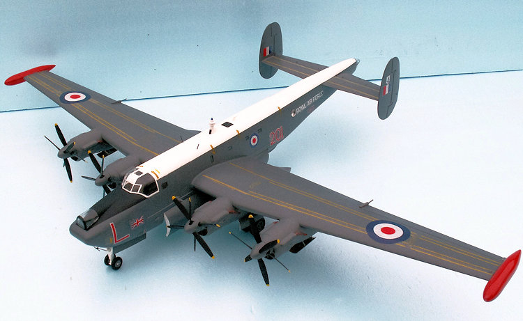
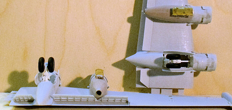
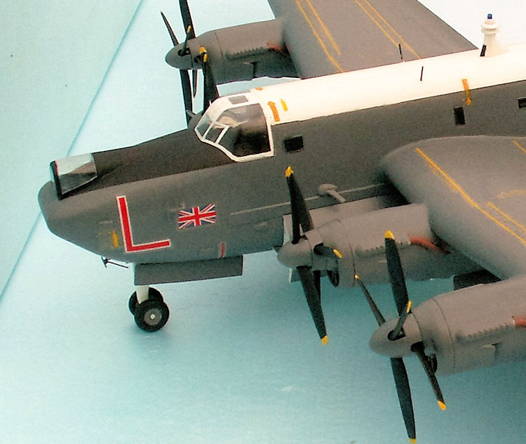
There was plenty of room behind the firewall of the Griffon engine for building the small Viper into a new enlarged nacelle. The exhausts were under the flaps, and a triangular piece of the flap had to be cut out to get clear of the hot exhaust of the Vipers. The new outer nacelle looked almost like the inner nacelles, only they were shorter and not pointed. The ventral air intake was fitted with a retractable door, which could be closed, when the unit was shut off.
The fuel for the Vipers should normally be kerosene, but they were actually run on high octane AVGAS as the Griffons did. This meant that there was no need for separate fuel tanks for the Vipers. They were fed quite normally from the fuel system of the aircraft. A problem was lead deposits on the turbine blades, but the Viper was sturdy enough to cope with this problem.
At first the Vipers were only allowed to run full power for 5 minutes, but this was sufficient to get the aircraft airborne. This meant that the Griffons had to run on high power settings for quite a long time, until the cruising altitude was attained and some AVGAS weight had been consumed.
Later the running time of the Vipers was increased step-by-step ending up with 4 hours of continuous operation. And in the end the Vipers could be operated from idle to full power in the air as long as required, but at that time, the phase 3 MR 3 Shacks were due to retirement a little more than one year later. The Vipers were not economical on fuel. However, when they were running, the Griffons could be run with reduced power settings, which minimized the risk of engine failures and following asymmetrical problems.
 Fatigue
testing, at the RAE at Farnborough, of one of the first MR 3 airframes revealed
that the safe life of the airframe was only about 3.600 hours – the operational
requirement was at least 10.000 hours! Avro dealt with the problem, and trebled
the fatigue life by strengthening the airframe. However, the power of the Vipers
meant in the end, that the fatigue life of the MR 3 was shorter than that of the
MR 2. This was the reason why the MR 2 was preferred for the AEW task.
Fatigue
testing, at the RAE at Farnborough, of one of the first MR 3 airframes revealed
that the safe life of the airframe was only about 3.600 hours – the operational
requirement was at least 10.000 hours! Avro dealt with the problem, and trebled
the fatigue life by strengthening the airframe. However, the power of the Vipers
meant in the end, that the fatigue life of the MR 3 was shorter than that of the
MR 2. This was the reason why the MR 2 was preferred for the AEW task.
The Shackleton was born with a large bomb bay, which could carry an ordnance of 12.000 lbs. This ordnance might consist of:
Up to three Mk 30 (Dealer B) 18 inch homing torpedoes
Up to 25 250 lbs. DCs
12 directional sonobuoys and 12 marine markers
2 sets of Lindholme Mk 2 rescue gear for SAR missions
One or two auxiliary 400 gallons fuel tanks
12 x 1000 lbs. general purpose bombs
Or a mixture of 1) - 6)
The top speed of the Viper Shack MR3 was 297 mph. This is only 13 m.p.h. faster than the MR 2. The take- off distance for the MR 3 was 5550 feet, and with Vipers running the distance was 4750 feet – all to clear a 50 feet obstacle.
The range was 2300 nautical miles, speed 190 mph at 5.000 feet. A MR 3 of 206 Squadron made in February 1959 a non-stop return trip from St Mawgan to the Canary Islands. This flight covered 3440 nautical miles and lasted 24 hours and 21 minutes. An extra pair of 400 gallons fuel tanks in the bomb bay were needed for this flight, and the average airspeed was a modest 165 mph.
The Shackleton MR 3 entered service with No. 220 Squadron late in August 1957. The following Squadrons all operated the MR 3 Shack: 42, 120, 201, 203, 206 and 220. The aircraft served until the end of 1971. The Shacks were gradually phased out and succeeded by the Hawker Siddeley Nimrod MR 1 from October 2nd 1969, when the first was delivered to the Maritime Operational Training Unit at RAF St. Mawgan.
| THE KIT |
The Revell kit of the Shackleton from 1997 is a copy of the original FROG kit from 1967. There are some differences, however. The FROG kit is moulded in a medium grey plastic, which is rather brittle by now, Revell used a very light grey plastic, which still is elastic and strong. The FROG kit can be put together with a fast CA glue. The Revell kit, however, must be glued together with ordinary plastic cement. The softeners in the plastic do not work properly with CA glue.
You can
normally count on that the general dimensions of a model kit are correct. In the
case of the Shackleton MR 3 you can’t: the overall length of the Shackleton MR 3
is 28.20 m, and this corresponds to 39.17 cm to a 1/72 scale. However, the
overall length of the model is only 37.1 cm. The fuselage length is too short by
2 cm, and that is too much (+ 5 %). I choose to ignore this flaw, but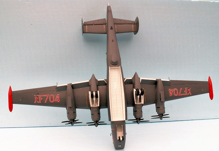 I am happy to conclude, that my AEW 2 conversion has the correct length of the
fuselage! Besides, I do not know exactly where to put in the extra pieces of
fuselage to get the length right.
I am happy to conclude, that my AEW 2 conversion has the correct length of the
fuselage! Besides, I do not know exactly where to put in the extra pieces of
fuselage to get the length right.
The Revell instructions are very much better than the original FROG instructions, 10 pages A4 and including how to paint the small parts as well as the completed model. Especially the decal guide drawings on page 9 and 10 are excellent. The assembly is quite straightforward if you follow the 35 steps of the instructions.
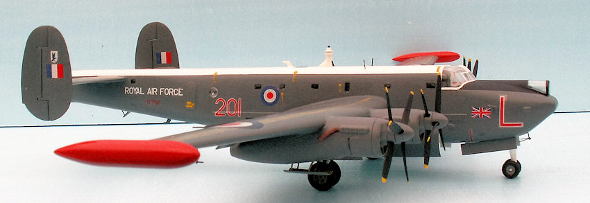
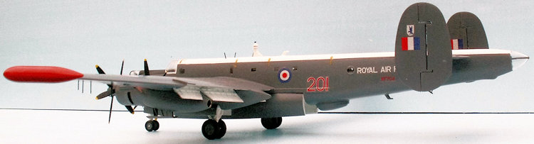
The decal sheet of the Revell kit is more comprehensive and has two options for either XF704 of Sqdn. 201 or XF730 of Sqdn. 42. The FROG kit offered either XF707 of Sqdn. 206 or 1722 of the South African Air Force.
However, the decals are not quite up to Cartograf standard. The yellow letters along the walking lines almost disappeared when the decals were put into water. A layer of clear varnish does not solve this problem. The carrier film of the decals is strong and flexible and will not crack. The RAF roundels might need a white disc underneath, if you do not want the dark sea grey color to bleed through the roundels.
The clear parts seem to have improved; the canopy has a much better fit and doesn’t need to be sanded thinner to fit properly to the fuselage. All of the rivets are there, although they seem a little reduced in length - but I might be wrong about that! The rivets have to be removed, if not completely, then to a degree where they are not dominating the surfaces and allow decaling without any problems. In my opinion it doesn’t matter if the pattern of the rivets can be seen, if you take a close look at the model. An aircraft like the Shackleton has not at all a very smooth surface!
The larger parts fit very well together. However, the starboard wing stub of the fuselage is too wide, and this flaw need to be corrected, but before the wings are glued in place. The port wing stub needs also some correction to fit perfectly to the wing. A great help is the bar that supports the wings and secures a strong connection to the fuselage. Another flaw is the engine nacelles, which are poor and need a lot of filling and sanding. The propellers fit much better than they did with the old FROG kit.
| CONSTRUCTION |
I organized the construction process in this way:
Propellers and front of Griffon nacelles
Fuselage with tail planes and fins
Main planes
Undercarriage
Engine nacelles with undercarriage legs and Vipers
Bomb bay doors
Clear parts – canopy
Small fittings –antennas and Orange Harvest
It is quite simple to construct a Shack from the Revell kit. The instructions are very good, and without ambiguities. Just for the sake of some challenge I decided to make my Shack a phase 3 with Viper auxiliary jet engines.
As other reviewers have dealt with the building of a standard MR 3 phase 2 Shackleton, I will concentrate on how to make the Viper conversion. Phase 2 because of the Orange Harvest radar warning receiver on the dorsal, phase 1 didn’t have this spark-plug- like gear.
The
first problem was to get a reliable sketch of the outer nacelle as modified for
Viper installation. A great help was a photo walk-around of the WR977, which is
on permanent exhibition at the Newark Air Museum. This Aircraft has the Viper
installation, and I printed the necessary photos out to get a clearer picture of
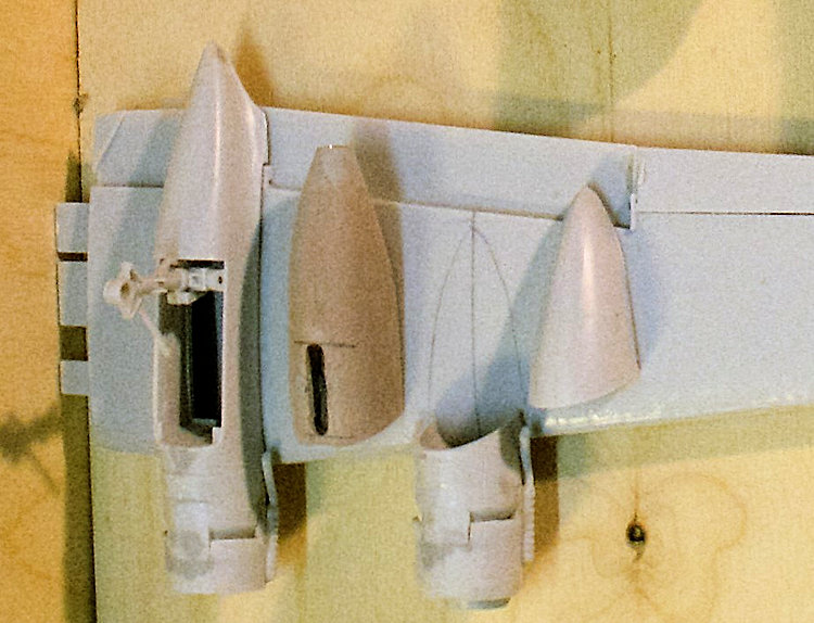
the Viper nacelle. At the rear there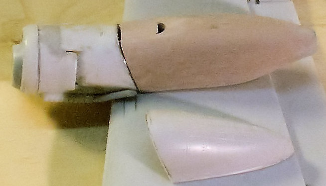 is the jet exhaust of course, and in the front end just behind the fire proof
bulkhead there is a ventral air intake, which can be closed by a door, when the
Viper is shut off to protect the gas turbine from dirt and birds.
is the jet exhaust of course, and in the front end just behind the fire proof
bulkhead there is a ventral air intake, which can be closed by a door, when the
Viper is shut off to protect the gas turbine from dirt and birds.
I made a working sketch and calculated that I needed 2 pieces of Ureol, each 6 x 1.9 x1.9 cm. It was not possible to calculate the gauge of the exhaust from the photos, but it is very important to get this gauge right. In the 1962 edition of the Observer’s book of Aircraft I found an aircraft with a similar powerplant: the BAC Jet Provost T 4. From the 3-view drawing it was possible to calculate the gauge of the exhaust: about 45 cm equal to 6 mm to a 1/72 scale - now that problem was solved!
The first thing to do was to drill a 6 mm gauge hole in the middle of the Ureol pieces for the exhaust openings – and put a 15 mm long piece of 6 mm brass tube into the holes. Next was to shape the nacelle as seen from the side, the upper side should match the curving of the wing. I figured out that the best way of mating the Viper nacelle to the outer Griffon nacelle, was to cut both nacelles oblique, as can be seen on the photo. By doing it in this way, the assembly point would also be well clear of the exhaust pipes of the Griffons, and make it safe to sand the assembly without risk of cracking the pipes.
Next
step was to shape the Viper nacelles as seen from beneath. With a small diamond
sanding drum on my Proxxon mini-drilling tool it was a rather easy job to remove
the Ureol not needed. When the right shape was at hand, it was time for the
final shaping to match the Griffon nacelle exactly. Most of the
 Griffon
nacelle had been removed and only a small piece of it was left. The Viper
nacelle should have exactly the same curving and thickness as the remains of the
Griffon nacelles as seen from the rear.
Griffon
nacelle had been removed and only a small piece of it was left. The Viper
nacelle should have exactly the same curving and thickness as the remains of the
Griffon nacelles as seen from the rear.
Now the correct shape of the complete Viper nacelles was at hand.
Next problem was to make the ventral air intake and the door to protect the Viper when not running. I calculated from the photos that the door should be 9 x 23 mm and about 0.3 mm thick. Since the doors should cover the intakes properly, I would suggest the openings to be about 6 mm wide and about 20 mm long. As it was possible to fix the nacelles firmly in a vice, it was an easy job milling the intakes with a 6 mm cutter. On that same occasion it would be very convenient to do the milling of the holes for the legs of the doors. With a 1 mm cutter I made the 8 holes half a mm from the walls of the intakes. Ureol is such a good material, that it allows a half mm wall standing without breaking. The holes should be 4 mm long and 3 mm deep. These oblong holes should be milled on either side of the points where the four legs of the door should be fastened to the nacelles. Since the legs are not perpendicular to the nacelles, it was not sufficient just to drill four plain holes, because it would be almost impossible to drill the holes at the correct angle!
Now it was time to make the two doors. They were cut from a 0.3 mm brass plate. The curving of the doors should match the curving of the nacelles exactly – Viper or Griffon, the same curvature. In my stocks I found a piece of wood with the required curving – convex curving that is. Now I just had to make a jig of plywood with the same concave curving. I had a 20 mm curved cutter, and this piece of tool milled exactly the concave curving that I needed. With these two wooden tools in hand it was quite simple and fast to shape the two doors, just two blows of a hammer did the job perfectly.
The remaining problem: How to make the four legs for each of the doors in the right size and fastened to the doors in the right angle. It was a soldering job without any doubt: the doors should not be too fragile when placed in the open position on the nacelles. The material was to be 0.8 mm gauge brass wire. I figured that the easiest way to do the soldering, would be if the legs were soldered on in pairs. This would simplify the process and provide the strongest construction, and I only had to solder 4 times!
Now how to make a pair of door legs: a piece of 29 mm 0.8 gauge brass rod is marked with 9 mm in the middle for the door and 2 x 10 mm remains for the two legs. The 9 mm piece is flattened by some hammer blows for two reasons: 1) the soldering area will be maximized and provide the strongest fix, and 2) and it doesn’t disrupt the thickness of the door too much. The 9 mm flattened piece in the middle is then getting its curving in the jig in the same way as the doors. Now the two legs were soldered to the upper side of the door using the jig and pliers to secure the right position. Two lines drawn on the jig secure the correct position of the legs during the soldering process.
 When all
four pairs of legs had been soldered firmly to the doors, it was possible to
bend the legs to the correct oblique angle as seen from the side. The legs need
some filing to make them thinner as seen from the front and the rear. The
thickness of the legs end up being approximately 0.5 mm.
When all
four pairs of legs had been soldered firmly to the doors, it was possible to
bend the legs to the correct oblique angle as seen from the side. The legs need
some filing to make them thinner as seen from the front and the rear. The
thickness of the legs end up being approximately 0.5 mm.
Now the four legs of the doors are due be placed into the four 4 mm long milled holes 0.5 mm close to the intake walls. The legs need to be cut down - a couple of mms - to obtain the right position of the doors as seen from the side, when opened during Viper runs. The legs are next fastened with small drops of a fast CA glue and finally the holes need a little filler on either side of the legs and some sanding to make the edge of the intake smooth.
Another small modification is necessary to do: The flaps need a V-shaped cut to clear the Viper exhaust. The V-pieces cut out should be glued to the wing exactly above the V-cut. When the flaps are glued in place - in max. down position - it is easy to see the meaning of the V-cut.
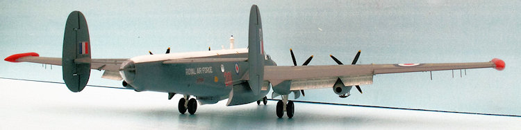
Before the fuselage halves are cemented together – remember to put the nose wheel leg in place and the windows of course, with the exception of the large circular observation windows, which must be replaced, as they are curving outwards. The new ones are to be put into place from the outside. The sparse interior in the cockpit section must also be in place and painted black. Do not forget to put some weight in the nose section! Between the office and the observer’s post there is plenty of room, and I placed 60 grams of 2 mm iron plate cut to small pieces, just to be sure not to end up with a tail-sitter.
The support spar for the main planes fits very well and firmly, and might almost keep the wings in place without using glue. However, for safety reasons, it is necessary to cement the wings to the fuselage. The fit to the fuselage need some correction. You will have to sand the stubs down to fit exactly with the wings. This correction is be done with the wings in place – not glued of course - and then it is possible to do the painting and decaling before the final assembly of the wings to the fuselage.
Now to the observation windows: As said they are convex curving and can be turned from a rod of transparent acryl. As the circular holes in the fuselage are 6 mm gauge, the gauge of the acryl rod must be 6.2 mm, and the part of the window protruding into the fuselage must be turned down to 6.0 mm. The windows will then fit perfectly and may be put into place without using glue. However, they should not be put into place until the fuselage has been painted.
| COLORS & MARKINGS |
The
first job was to paint the propellers, but each blade must be sanded a bit more
pointed and the tips to about half thickness. Since the plastic is very light
grey, it was enough to paint the tips once with yellow (HB # 69) The XF704 had
yellow propeller tips in 1965. The characteristic red-white- red tips appeared
later in the Shack’s career. The propeller blades were painted matt black (Model
Master flat black # FS 37038), and again one rather thick layer was enough. The
spinners and engine cowling fronts got painted twice with dark sea gray (HB #
164). The intake filters got a light tan (HB # 118). Next the propeller units
were to 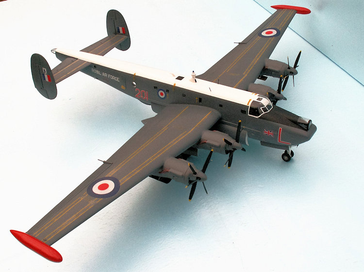 be
assembled and the shafts were fixed in place by the small discs, which were
secured with a drop of glue.
be
assembled and the shafts were fixed in place by the small discs, which were
secured with a drop of glue.
The first finished items, and the last ones to be placed on the finished model!
The rest of the painting job was without any problems. I started with the assembled wings, complete with nacelles and Vipers and they got dark sea grey twice, and a layer of clear varnish before the decaling. It is definitely easier to handle a wing than a complete aircraft during the painting and decaling process!
The fuselage is also dark sea grey, but with the top in white. First did the top get three layers of gloss white (HB # 22), no masking necessary. The windows had to be masked off with small pieces of Tamiya-tape and the white top had to be masked off, too, to get a proper straight line between the white top and the dark sea grey of the rest of the fuselage. Always two layers of dark sea grey. The inner side of the bomb bay doors and the bomb bay are white – three layers. The bomb bay doors outer side dark sea grey twice.
The canopy framing was hand painted white with a very fine brush and a very steady hand. In the same way the other transparencies on top of the nose – black- and in the rear – dark see grey. The undercarriage legs are white, and the tires are either tire- black or a very dark grey (Antracitgrau, Model Master Ral 7016), wheel hubs are dark sea grey – not metallic as suggested in the instructions. Wheel wells are white, and so are the inner sides of the doors. The outer side of the doors are dark sea grey. The Orange Harvest gear is white, with a black vertical stripe on the lower half of the front. The top is transparent blue (Revell 752).
The only problem about the decals concerns the four landing lights on the underside of the wings. The large red X will more or less cover the lights on either wing. This is my solution to solve this problem: You must make two holes in the decals exactly matching the position and the size of the lights!
The
bigger of the lights is 4 mm gauge and the smaller is 3 mm gauge. The distance
between the two lights is 5.5 mm on the starboard
 wing and
4.5 mm on the port wing. I wonder why the distance between the lights is not the
same on both wings, but there is without any doubt a good reason for that.
wing and
4.5 mm on the port wing. I wonder why the distance between the lights is not the
same on both wings, but there is without any doubt a good reason for that.
My revolving-head punch possesses luckily both a 3 mm and a 4 mm punch. I used a small piece of cardboard for a model and punched a 3 mm hole and a 4 mm hole with an exact distance of 5.5 mm, and another two holes with a distance of 4.5 mm between them. The centerline through the two holes should be perpendicular to the edge of the cardboard. My punching model was ready!
Then I looked at the decal guide on the last page of the instructions, and it was easy to see on the fine drawing, where the holes should be made in the decals. I fixed the model to the decal at the right spot and it was easy to punch the holes through the model. It was a special joy afterwards to put the XF704 decals on the underwings and see the lights exactly beneath the punched holes!
The decal sheet does not have the rescue markings, which appear on the WR977. I don’t know if the XF704 had these markings on the sad day of the 8th of December 1965 when the aircraft crashed in the Firth of Murray. I decided nevertheless to put these markings on the model – since I had them in my stocks. There are eight of them placed on the top of the fuselage, pointing at the direction of the escape hatches.
Decal no 42 consists of eight small white squares 2.5 by 2.5 mm. They were supposed to be the RR markings on the Griffons. I would have expected to see the RR logo on the markings, but without I preferred not to apply them.
Cartograf would definitely not just make eight white squares without the well-known Rolls Royce logo!
| FINAL CONSTRUCTION |
The small antennas of the kit are very fragile, and these parts will often be either bent or even broken. However, the solution of this problem is to make the antennas from brass rod, 0.8 and 0.4 mm gauge. With the aid of a suitable jig to keep the very small parts in the right place during the soldering, it was quite easy to produce some durable antennas. The antennas in question are these on either side of the front fuselage, and the one in front of the nose wheel.
Besides two very fragile rod antennas, which are situated about 3 cm in front of the plinth of the Orange Harvest Gear, need to be replaced and are made from 0.6 mm brass rods.
 On the
underside of the wings two pitot tubes are placed rather close at the landing
lights and touching the big red X of the markings. Further outwards there are
three thin rod antennas, all in the same distance from the front edge of the
wing as the pitot tubes. The pitot tubes were O K to be placed on the model, and
the 6 thin antennas were not supplied with the kit, and they were just made of
0.4 mm brass rod. The very last item was to produce a pair of fuel jettison
pipes, as they were not parts of the kit either. They were not difficult to
produce from small pieces of Ureol and 0.8 mm gauge brass tube. They are placed
on the rear edge of the upper sides of the wings, just where the flaps end, and
the ailerons begin.
On the
underside of the wings two pitot tubes are placed rather close at the landing
lights and touching the big red X of the markings. Further outwards there are
three thin rod antennas, all in the same distance from the front edge of the
wing as the pitot tubes. The pitot tubes were O K to be placed on the model, and
the 6 thin antennas were not supplied with the kit, and they were just made of
0.4 mm brass rod. The very last item was to produce a pair of fuel jettison
pipes, as they were not parts of the kit either. They were not difficult to
produce from small pieces of Ureol and 0.8 mm gauge brass tube. They are placed
on the rear edge of the upper sides of the wings, just where the flaps end, and
the ailerons begin.
Finally the propeller units can be put into place. Since there was excessive paint in the joints, it was not necessary to use glue, and the bomb bay doors can at length be glued in place. I had chosen to make the model with the doors in open position, because I want to put some equipment into the bomb bay once in the future – when I know more precisely, what the equipment looks like.
| CONCLUSIONS |
Building the Revell Shackleton MR 3 phase III Viper was a most interesting job. It was of great advantage to have gained some experience with the old FROG kit - just one year before. My experience meant that my attitude towards the job was of a more relaxed kind. The Viper modification was a challenge of course, but only a small one compared to making an AEW 2 of the old FROG kit.
The
Revell kit is definitely recommendable for an experienced modeler. However, it
is not recommendable for a beginner. The Revell kit is not exactly the same as
the old FROG kit. It is better – especially because the plastic is still fresh
 and
elastic.
and
elastic.
During the building of my Shackleton MR 3, I came across another Shack MR 3 kit. It was without box, instructions or decals. Just a pair of plastic bags containing a complete kit in off-white plastic. It must be one of the Russian reissues of the FROG kit, which were produced after the closure of FROG in 1976 and before the Revell kit was released in 1997. The price was a modest US $ 3.5, and time will show, what specific aircraft I might once in the future get out of this kit.
Maybe an MR 3 with the correct length of the fuselage?
| REFERENCES |
Chris Ashworth: AVRO’s Maritime Heavyweight the Shackleton, Aston Publications 1990 ISBN 0-946617-16-9
This book contains the full story of the development of the Shackleton, its service life worldwide with the RAF squadrons, and the individual history of all of the 188 Shackletons that were built. It is highly recommendable if you want to know a lot about this outstanding aircraft and its role in the RAF. The book contains more than 250 illustrations, mostly b/w photos but also a handful of color photos, and color drawings of the three main variants.
William Green & Dennis Punnett: Observer’s book of Aircraft 1962 Edition p. 136-37, Frederick Warne & Co Ltd. 1962 (no ISBN number)
Air Commodore Graham Pitchfork: the RAF day by day, Sutton Publishing 2008 ISBN 978-0-7509-4309-3
Wikipedia.org - articles on DH Sprite & Super Sprite rocket engines, Lindholme Gear, AVRO Shackleton and Orange Harvest.
http://www.britmodeller.com, walk-around photo series of Shackleton MR 3 phase III on permanent exhibition at the Newark Air Museum.
Thanks t
If you would like your product reviewed fairly and fairly quickly, please contact the editor or see other details in the Note to Contributors.