Pro Resin 1/72 Avro 707C
| KIT #: | R 72-029 |
| PRICE: | Around $40 or so. |
| DECALS: | One option |
| REVIEWER: | Clare Wentzel |
| NOTES: | Resin with vacuformed canopies |
| HISTORY |
The Avro 707 program was initiated in an attempt to generate aerodynamic data for the upcoming Vulcan bomber. Avro intended to produce the aircraft quickly and cheaply using some off-the-shelf components. This version, the 707C was a two-seat side-by-side design planned to provide future Vulcan pilots with some experience in the handling of delta wing aircraft. As it turned out, delays in the 707 program resulted in it providing very little assistance to the Vulcan program. The Avro 707 program aircraft were therefore utilized for various general type aviation experimental programs.
The solitary two-seat version that was produced, the subject of this review, still exists and is on display at the RAF Museum, Cosford. As with most research aircraft, it featured many appearance changes during its career.
| THE KIT |
 The kit
consists of 40 resin parts, two vacuformed canopies and a decal sheet for the
single example of this unique airplane. The parts are contained in a resealable
plastic bag within a sturdy two-piece cardboard box. The resin is somewhat
brittle and many of the pour spouts are very thick necessitating the use of your
model saw. Finely engraved surface detail on all the parts is excellent. Very
few surface pits were apparent although the leading edges of the wings showed
several. Apparently these parts were separated from their pour spouts at the
factory and formed to shape. I was not happy with the arrangements of the
smaller parts. They have several parts mounted to a pour spout but they do not
have any protection for the parts. As a result, most of the long, thin parts
such as landing gear supports and pitot tubes were broken when I received the
kit.
The kit
consists of 40 resin parts, two vacuformed canopies and a decal sheet for the
single example of this unique airplane. The parts are contained in a resealable
plastic bag within a sturdy two-piece cardboard box. The resin is somewhat
brittle and many of the pour spouts are very thick necessitating the use of your
model saw. Finely engraved surface detail on all the parts is excellent. Very
few surface pits were apparent although the leading edges of the wings showed
several. Apparently these parts were separated from their pour spouts at the
factory and formed to shape. I was not happy with the arrangements of the
smaller parts. They have several parts mounted to a pour spout but they do not
have any protection for the parts. As a result, most of the long, thin parts
such as landing gear supports and pitot tubes were broken when I received the
kit.
| CONSTRUCTION |
Construction starts with the cockpit. Two nicely molded ejection seats with
integral seat belts are provided. They fit into a fairly well detailed cockpit
tub that fits between the fuselage halves. No problem, right? – wrong! The two
seats would not fit into the tub. I kept thinning them and removing some
details from the tub until they fit. At this point, the seats measured a scale
12 inches wide. Next, the tub would not fit into the fuselage. After thinning
the sides of the tub as much as possible and also thinning the sides of the
fuselage, I got it to fit. I ended up cracking the side of the fuselage in
the process but was able to fix it without problems. Before closing the
fuselage, I glued the nose wheel well in place (there were no noticeable
mounting provisions) and added some weight to the nose. I did not include
the jet exhaust at this time, opting to install it at the end. One thing
to note before gluing the nose wheel well in place is to make sure that the
mounting location of the nose gear i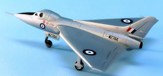 s
clear and cleaned up. It is probably a good idea to remove the nose gear
from the sprue so that it can be test fitted into the well. I found some
excess resin in the landing gear strut mounting areas, both in the nose and in
the wings.
s
clear and cleaned up. It is probably a good idea to remove the nose gear
from the sprue so that it can be test fitted into the well. I found some
excess resin in the landing gear strut mounting areas, both in the nose and in
the wings.
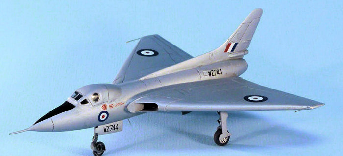
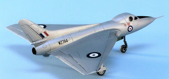
The next part of the construction consists of the wings, the intakes and the fin/rudder. Left and right wings are one-piece and mount to formed stubs on the fuselage. Having said that, I found that the mating surfaces were not flat. It took a fair amount of sanding to make the parts fit and even then, filler was required. I used a piece of wet/dry sandpaper, taped to my workbench for the sanding. The intakes were mounted on fairly large pouring spouts and also required the modeling saw to separate them. Here again, lots of sanding was required to make them fit into the openings between the fuselage and wings. This was not hard, just a lot of trial and error. The vertical stabilizer was next. It had to be separated from its long spout and then fitted to the curve of the upper fuselage. No mounting locations are provided so this has to be done carefully. The example of the 707C located at the RAF Museum has what looks like an antenna pod located on the front of the fin. This is not included on the kit part. I found some photos of the aircraft at earlier times that did not have the antenna pod so I was comfortable to not modify the kit part.
The
canopy was to be mounted at this time also. Two canopies are provided in case
one is ruined. I was able to trim the canopy and got it to fit the fuselage
pretty well. Some filler was required along the rear edge (and I didn’t get the
surface perfect) but it 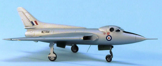 looked
ok in the end. I was surprised that the canopy didn’t follow the opening
line of the original airplane. I ended up having to scribe a line onto the
fuselage to simulate that panel line. This may have been a miscalculation
on the part of the kit designers. If they had moved the ejection seats
back 1/8-inch and extended the canopy by a similar amount, the canopy trim line
would have been accurate and the pilots could have used the side windows more.
Since I have not seen a photo of the real aircraft with the canopy open, this is
just speculation.
looked
ok in the end. I was surprised that the canopy didn’t follow the opening
line of the original airplane. I ended up having to scribe a line onto the
fuselage to simulate that panel line. This may have been a miscalculation
on the part of the kit designers. If they had moved the ejection seats
back 1/8-inch and extended the canopy by a similar amount, the canopy trim line
would have been accurate and the pilots could have used the side windows more.
Since I have not seen a photo of the real aircraft with the canopy open, this is
just speculation.
The landing gear came next. I was disappointed with the fixation of the wheels to the gear struts. The struts simply had a small pimple that was supposed to fit into a slight dimple in the wheels. This took some care to ensure that the wheel was correctly aligned. The mounting of the gear struts to the wings offered some problems also. The mounting holes were very shallow and in one case the opening was partially blocked with excess resin. As I mentioned above, extra time spent cleaning up the wheel wells before the wing is mounted to the fuselage will help here. The actuating rods were scratchbuilt as were the scissors links for the struts. The original rods were broken in the kit and the links could not be removed from the spout without them disintegrating.
The
nose gear was one of the more frustrating assemblies that I have worked with.
The bottom fork of the gear is a separate part. It mounts on an angle to
the nose gear strut and the joint is heavily loaded when the model is setting
upright. This joint must be strong while being careful not to show any
excess glue. Next came the fender for the nose wheel. The part is
attached to the pour stem by a thin web all around the outside of the fender.
Also, the two braces on each side had a web of resin between them that had to be
cleaned up. I soon found out that it is impossible to hold the fender and
try to clean up the injection 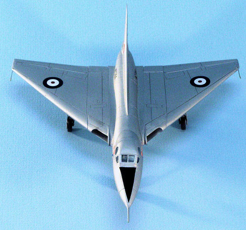 seam
without breaking off one of the side brace sets. After crawling around on
the floor for a half-hour, I found the fender but did not find the broken-off
set of braces. Time for more scratch building. This is one kit that
would have benefited from the addition of white metal landing gear parts.
seam
without breaking off one of the side brace sets. After crawling around on
the floor for a half-hour, I found the fender but did not find the broken-off
set of braces. Time for more scratch building. This is one kit that
would have benefited from the addition of white metal landing gear parts.
The gear doors were well detailed including built-in mounting provisions. They were easy to mount and looked good. Next the pitot tubes were added, stretched sprue to replace broken kit parts and finally the nose probe. This part came through intact.
| COLORS & MARKINGS |
There is little choice here. The single aircraft was painted silver with a flat black anti-glare panel. The kit decals depict the markings of this airplane. They went on well although I tried to get the wing cockades to snuggle down a little more and they went all wrinkled. I replaced them with some from the spares box.
| CONCLUSIONS |
I have built resin models before and have not encountered near as many problems as this model. A lot of the problems would have been prevented by, in my opinion, a better design. Molded-in protection for some of the small, fragile parts would have gone a long way. Having said that, I was pleased with the final result. I love delta wings and this model represents one of the earliest and cleanest designs. It can be built by most modelers who have at least minor experience with scratch-building minor components.
| REFERENCES |
I used the Internet to find as many photos of the original as possible. Other than that, I used the excellent three view drawings contained in the one-page directions. I expanded the drawing to 1/72 scale and used it for reference.
April 2007
Copyright ModelingMadness.com
If you would like your product reviewed fairly and fairly quickly, please contact the editor or see other details in the Note to Contributors.