Airfix 1/72 L.E.M.
|
KIT: |
Airfix 1/72 L.E.M. |
|
KIT # |
3013 |
|
PRICE: |
@ €7.00 |
|
DECALS: |
yes |
|
REVIEWER: |
|
|
NOTES: |
|
BACKGROUND |
Well, I´ve
completed my trip into 1969 and have at least two completed models to
show. I´ll show them to you as I´ve promised to although I´m not
satisfied with them. They haven´t come out of the process as I´d like to
have seen them, but they at least testify to my personal approach with
its strengths and weaknesses. And I´ve got to admit that with the
 incredible quality level displayed on M2 on an everyday basis, I´d like
to show you that there´s also everyday modeling around. If I dare
displaying my stuff, than many others might also do, and with
constructive comments and criticism we´ll all benefit.
incredible quality level displayed on M2 on an everyday basis, I´d like
to show you that there´s also everyday modeling around. If I dare
displaying my stuff, than many others might also do, and with
constructive comments and criticism we´ll all benefit.
OK, end of introductory excuse.
Part 1 – Admitting cerebral overload
I saved and printed the old FSM article ( http://members.aol.com/TranBaseDiorama/FSM.htm ) on correcting the Airfix LM and tried to get through it. Well, in spite of reading and rereading it - throughout the entire project I had the distinctive feeling I didn´t get to grips with this weird craft, especially the ascent stage with its many angles and varying planes. I couldn´t grasp the thing in my mind and still am not sure which panels really should be finished which color ... If you´re more serious, than also consider the following article that endeavours to correct mistakes made in the former one and applies to Revell´s 1:48 scale kit. http://www.ninfinger.org/~sven/models/lmarticle/page1.html I have to admit my mind was already off course trying to worm through the first article so I gave up on trying to get a synopsis from both...
|
THE KIT |
Please visit the preview for a look in the box.
All in all the kit´s fit was surprisingly effortless. I had no problems from that and guess I wouldn´t have to use much putty building it OOB.
|
CONSTRUCTION |
 Real
construction began with the body of the descent stage, which is pretty
straightforward, being mainly an octagonal box with a rocket motor
sticking out of it. You are requested to build up one side and produce a
circular bump on another, plus the outline of the equipment bay door. I
achieved this pretty soon with sheet styrene plus some putty for the
former and with a little dental casting resin (the red stuff) poured into
a silicone mixing jar for the midst plus with scribing for the latter. In
the end, I cut out the equipment bay door later and should have done it
already at that stage. But I was quite happy when I started wrapping the
craft with foil. The instructions call for various shades of foils,
making the task yet more complicated.
Real
construction began with the body of the descent stage, which is pretty
straightforward, being mainly an octagonal box with a rocket motor
sticking out of it. You are requested to build up one side and produce a
circular bump on another, plus the outline of the equipment bay door. I
achieved this pretty soon with sheet styrene plus some putty for the
former and with a little dental casting resin (the red stuff) poured into
a silicone mixing jar for the midst plus with scribing for the latter. In
the end, I cut out the equipment bay door later and should have done it
already at that stage. But I was quite happy when I started wrapping the
craft with foil. The instructions call for various shades of foils,
making the task yet more complicated.
Now I had bought an extra mylar emergency blanket (which is mandatory for German first aid car kits) and used it. It wasn´t a real success. Although the real thing, it did not work in this scale, being too elastic – so this is a typical example of the scale effect. Ship modelers know better than to carve their ships of the line´s planks from oak, as its structure is much too coarse – pear, for instance is much better.
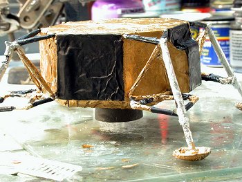 As I
didn´t find the right gold foil in the candy area (what I found was
structured and printed), I finally used household aluminum foil and
painted it appropriately. That of course does not look just like the real
thing, but I used it as I didn´t find a better alternative. I might have
put things aside at that point and kept on searching, but I didn´t. The
foil could be sufficiently crumpled and stayed that way, which was
satisfying. I glued it with white glue. Mounting and wrapping the legs
was fiddly, to say the least, and I was rather happy when I had them
completed. I followed FSM instructions in correcting some minor issues at
the descent stage and completed it after some while, painted in gold and
black and silver.
As I
didn´t find the right gold foil in the candy area (what I found was
structured and printed), I finally used household aluminum foil and
painted it appropriately. That of course does not look just like the real
thing, but I used it as I didn´t find a better alternative. I might have
put things aside at that point and kept on searching, but I didn´t. The
foil could be sufficiently crumpled and stayed that way, which was
satisfying. I glued it with white glue. Mounting and wrapping the legs
was fiddly, to say the least, and I was rather happy when I had them
completed. I followed FSM instructions in correcting some minor issues at
the descent stage and completed it after some while, painted in gold and
black and silver.
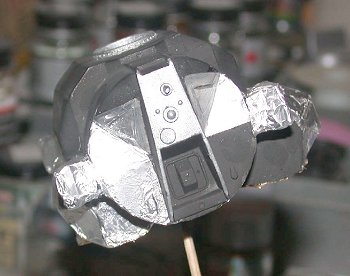
Now the
ascent stage simply slipped my perception, and I wasn´t really happy when
I dremeled the shaded areas depicted in the FSM article away. I used
sheet and Tamiya putty to build them up again as per instructions. There
were some points in construction that I really didn´t understand,
especially where the docking collar was concerned, but I was subliminally
annoyed with me and the project so didn´t ask for advice and left that
OOB. A common trait with me. When things go wrong, the balance of the
project starts tilting slightly; it may recover, but it may also reach
the point where I decide to complete the (%/&% thing „as is“ and try not
to care about the shortcomings. If I get the feeling that what I can do
to correct things will not help things and make them only more annoying,
I complete it this way in order to avoid trashing the kit. I must
admit that over time, these situations happen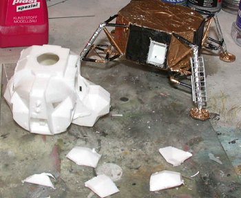 on a higher level and less easily, so a learning curve is perceptible.
Well, perhaps someone out there recognizes him - or herself at some
point.
on a higher level and less easily, so a learning curve is perceptible.
Well, perhaps someone out there recognizes him - or herself at some
point.
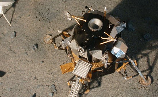
After correcting the basic shape came mounting the thruster mounts, which had to be corrected themselves as the areas where they are applied are the ones you have to perform surgery on. Having completed this, I started wrappng the ascent stage with aluminum foil. I tried to recreate the crumpled look I had seen in pics of the real thing, redoing it until I found I couldn´t improve this time. Next came painting the craft, and that was a hard task. I finally decided which route to follow and which parts had to become black and which not. Having achieved this, I built the access area and various antennae, correcting some of it and leaving some OOB. The thrusters were dremeled out, painted exhaust metal and glued. The decals were applied and corrected per instructions. Now came the last chapter.
The
exhaust from the ascent thrusters is deflected from the thin skin of the
ascent stage by exhaust shields that are fixed to the descent stage. You
can see them quite nicely silhouetted in the opening scene of
„Independence Day“. In the kit, they are moulded integral with the four
lower thrusters. Now the FSM article asks you to remove them from the
thrusters – as in reality - and scratchbuild this assembly. Well, I
didn´t. I had more than enough
 fun building the rigging with the ascent
stage firmly attached to the descent stage! In my imagination I saw
myself propelling the craft to a low and possibly instable near-earth
orbit during the task of building and aligning four of them fiddly
mounts. So I used lengths of wire that were attached by heat. They were
heated with a spirits burner and then carefully attached to their various
positions. I use the same method for gun barrels made from hypodermic
needles and prefer it towards gluing.
fun building the rigging with the ascent
stage firmly attached to the descent stage! In my imagination I saw
myself propelling the craft to a low and possibly instable near-earth
orbit during the task of building and aligning four of them fiddly
mounts. So I used lengths of wire that were attached by heat. They were
heated with a spirits burner and then carefully attached to their various
positions. I use the same method for gun barrels made from hypodermic
needles and prefer it towards gluing.
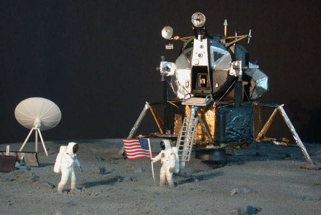
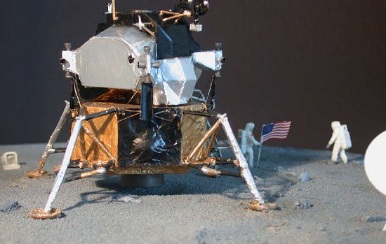
So I finally had a LM standing on my workbench, nowhere near perfect, but finally looking acceptable to me. I built the various experemintal devices and painted them according to reference found in the NASA´s image banks. The astronauts were sprayed white, the visors were picked out gloss black and some details grey and red. Their suits were weathered with grey where they were covered with lunar dust. Armstrong´s flag was made using the kit decal mounted on a piece of aluminum foil to give it some more stability.
Now came the fun part of the whole affair, and as with other fun, it was soon over. I made a base to take pics on.
First I
took a big plastic thing you put under flowerpots to retain excess water
and filled it with crudely cut pieces of styrofoam until a bit under the
edge. Then I mixed liberal amounts of the putty you use to full cracks in
walls (spackling compound, Ed) and filled it over the styrofoam. I embedded little stones I had
picked up on a gravel track near my home as „lunar rocks“. I had taken an
impression of the „astronauts footprints“ from the Airfix base and upon
placing the LM into the 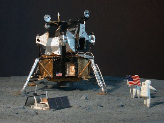 wet putty, I produced footprints with a piece of
silicone mounted on a toothpick. I placed the various experiments around
the LM, producing „tracks“ with my footprint tool. In the end, the putty
was too coarse to really accept impressions, but I´m sure it´ll work with
plaster next time: I´m planning to produce another, smaller diorama for
permanent use as this one is over 30 centimetres in diameter and eats up
too much shelf space.
wet putty, I produced footprints with a piece of
silicone mounted on a toothpick. I placed the various experiments around
the LM, producing „tracks“ with my footprint tool. In the end, the putty
was too coarse to really accept impressions, but I´m sure it´ll work with
plaster next time: I´m planning to produce another, smaller diorama for
permanent use as this one is over 30 centimetres in diameter and eats up
too much shelf space.
Next, I used sea sand picked up in the baltic to make the structure a little coarser, and that worked well on the one hand, but finally killed the footprints. I´m yet rather pleased with the structure as shown in the pics. The sand was fixated with spray glue, and after drying, I sprayed the entire ground with varying shades of grey from various directions until I was satisfied. After drying, the module and the various accoutrements were placed on the base. I weathered them a bit more with grey to blend them in.
The pics were taken with my Coolpix 995 mounted on a tripod, set at manual with aperture priority at f~ 10. A black cardboard served as backdrop, lighting was by a single halogene lamp from rather low to produce stark shadows.
|
CONCLUSIONS |
This is a fascinating subject and a kit with potential. In hindsight, I´d probably had more fun with Revell´s 1:48 version, but couldn´t obtain it. Now your modeling of course reflects your character, and in so far I learned more about me and my - but I wrote that in the start already.
August 2003
|
REFERENCES |
http://www.apollosaturn.com/frame-asc.htm
http://members.aol.com/TranBaseDiorama/FSM.htm
http://www.ninfinger.org/~sven/models/lmarticle/page1.html
http://users.specdata.com/home/pullo/
http://users.specdata.com/home/pullo/lm_mis1.htm
http://sln.fi.edu/pieces/schutte/LMintro2.html
http://nssdc.gsfc.nasa.gov/nmc/tmp/1969-059C.html
http://www.cradleofaviation.org/exhibits/restorations/lem.html
http://www.space.com/missionlaunches/kelly_obit_020326.html
http://www.geocities.com/CapeCanaveral/Hangar/2883/lm_page/lm_facts.html
If you would like your product reviewed fairly and quickly, please contact
me or see other details in the Note to
Contributors.