
| HISTORY |
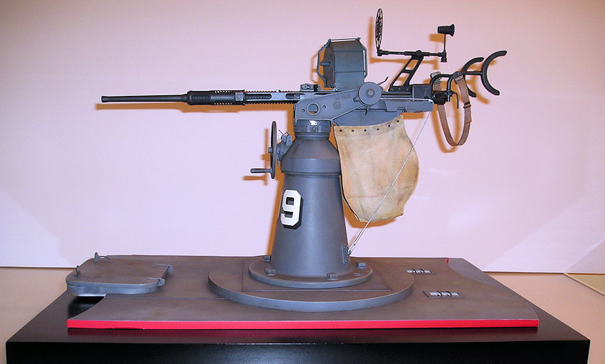
The deed is done; the project that consumed my time through December of 2014 and six months of 2015! Some people forget the inspirations of their youth as they grow older and they become engrossed in adult life but us artist types are blessed with the ability to carry them forever as if they were locked safely away in a steamer trunk. I was 14 years old in 1963 when I saw the movie ‘PT-109’ for the first time and left the theater immensely inspired with not only the story behind that boat and its crew, but all things related to PT (Patrol, Torpedo) boats and the exploits of all their crews in the Pacific Theater of World War Two. The PT- 109 was an early 80’ Elco torpedo boat made famous by its last commander, Lieutenant, Junior Grade John F. Kennedy. You probably are familiar with the story of how the PT 109 was cut in half by a Japanese destroyer while on night patrol in August of 1943 and how Lt. J.G. Kennedy and his executive officer, Ensign Leonard Thom saved the majority of their crew. Most Elco series PT-103 through PT-196 boats had a single rapid fire Swiss Oerlikon 20mm Mark 4 anti-aircraft gun on a pedestal mount in the stern position so replicating in scale a portion of that position was my goal.
WHERE TO START?
 So what’s a fella
to do when there is no commercially available model kit of an Oerlikon 20mm
anti-aircraft gun? Begin with a ton of research and then start scratch building!
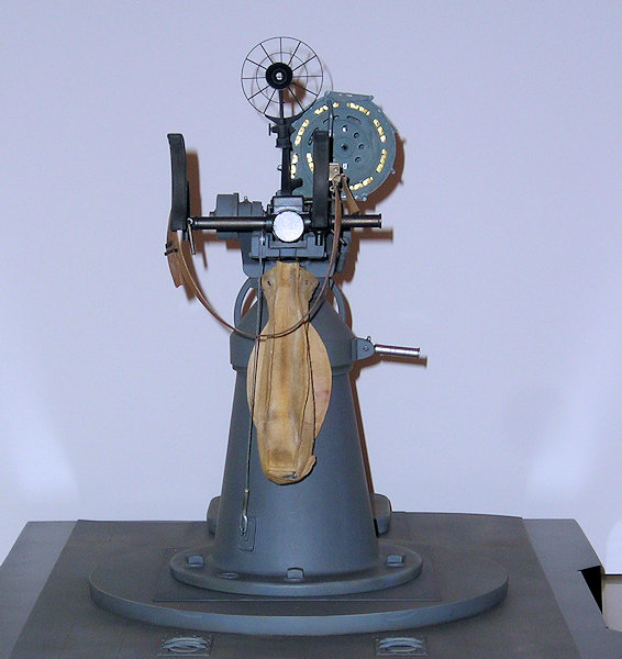
I wanted my finished model, in 1/6th actual size scale (two inches equals one
foot in real life), to portray the 20mm gun position as it would have appeared
when the boat was delivered to PT Squadron 2 at Tulagi in 1942. This would have
been about a year before Lt. J.G. Kennedy would take command of the boat. At
that time, the boat was painted in a two-tone gray scheme of dark Navy gray for
everything above decks over medium gray for the hull sides as delivered by the
Electric Boat and Yacht Company (ELCO), Bayonne, New Jersey. I wanted the model
gun to traverse, elevate and jack in the same manner as the actual gun and
mount. I also wanted it to depict a gun ready for action and include the canvas
bag which collected spent cartridges, have the cocking rope attached, and show
the gunner’s back strap and ammunition in the drum magazine; all details missing
from museum displays in the best of condition.
So what’s a fella
to do when there is no commercially available model kit of an Oerlikon 20mm
anti-aircraft gun? Begin with a ton of research and then start scratch building!
I wanted my finished model, in 1/6th actual size scale (two inches equals one
foot in real life), to portray the 20mm gun position as it would have appeared
when the boat was delivered to PT Squadron 2 at Tulagi in 1942. This would have
been about a year before Lt. J.G. Kennedy would take command of the boat. At
that time, the boat was painted in a two-tone gray scheme of dark Navy gray for
everything above decks over medium gray for the hull sides as delivered by the
Electric Boat and Yacht Company (ELCO), Bayonne, New Jersey. I wanted the model
gun to traverse, elevate and jack in the same manner as the actual gun and
mount. I also wanted it to depict a gun ready for action and include the canvas
bag which collected spent cartridges, have the cocking rope attached, and show
the gunner’s back strap and ammunition in the drum magazine; all details missing
from museum displays in the best of condition.
RESEARCH AND DRAWINGS: A NECESSARY FIRST STEP
I’ve been collecting information and reference on PT boats, well, since I saw the movie! Additional internet research and examination of photographs of existing examples of the weapon in different museums, photographs, and measurements I was fortunate enough to be allowed to take myself of the real weapon at Chicago’s Museum of Science and Industry, along with a copy of the U.S. Navy technical manual for the gun allowed me to develop and draft accurate scale plans. I am retired from a career as a freelance commercial artist and as such, I’ve done a great deal of mechanical drawing for machine companies over the years and that experience helped immensely. For the scratch-builder, I cannot stress enough the importance of developing accurate five-view drawings of each part of a given project before you start building. It is much better to work out any potential fit problems or pitfalls on paper than to find you’ve built yourself into a corner.
| CONSTRUCTION |
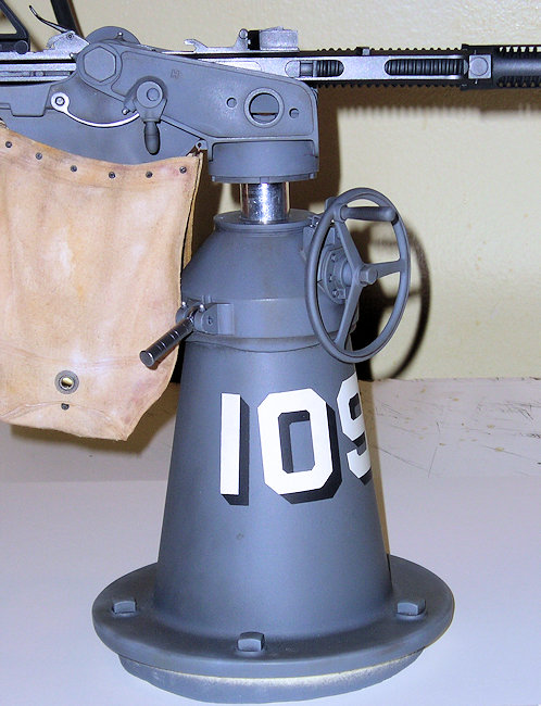
 I began
construction on this project with the gun pedestal, building it from basswood
using the tried and true ‘stringer and former’ method utilized by RC model
airplane builders. In this case, the cone shape of the pedestal was created by
center drilling a ¼” hole in disks of basswood cut to size minus the thickness
of the wood I would use to cover them and then aligning them on ¼” dowel rod to
form the basis for the pedestal shape. Once covered with wood strips, this was
then given several coats of fiberglass resin with a disposable paint brush and
sanded smooth when fully cured. The fiberglass resin seals the wood and makes it
easier to sand to a smooth surface. After detailing the rim and mount for the
crown with styrene stock, adding weld seams with A-B epoxy putty, the mounting
panel for the lower mount for the cocking cable, and locations for the five
bolts that attached the pedestal to the deck of the boat, I now had a pattern
from which to make an RTV rubber mold. Since I knew the weight of the finished
model gun would be substantial, I poured a solid resin copy of the pedestal to
support it. That copy had to then be center drilled 1” in diameter to accept the
shaft from the crown piece which would allow the gun to traverse 360 degrees
when completed.
I began
construction on this project with the gun pedestal, building it from basswood
using the tried and true ‘stringer and former’ method utilized by RC model
airplane builders. In this case, the cone shape of the pedestal was created by
center drilling a ¼” hole in disks of basswood cut to size minus the thickness
of the wood I would use to cover them and then aligning them on ¼” dowel rod to
form the basis for the pedestal shape. Once covered with wood strips, this was
then given several coats of fiberglass resin with a disposable paint brush and
sanded smooth when fully cured. The fiberglass resin seals the wood and makes it
easier to sand to a smooth surface. After detailing the rim and mount for the
crown with styrene stock, adding weld seams with A-B epoxy putty, the mounting
panel for the lower mount for the cocking cable, and locations for the five
bolts that attached the pedestal to the deck of the boat, I now had a pattern
from which to make an RTV rubber mold. Since I knew the weight of the finished
model gun would be substantial, I poured a solid resin copy of the pedestal to
support it. That copy had to then be center drilled 1” in diameter to accept the
shaft from the crown piece which would allow the gun to traverse 360 degrees
when completed.
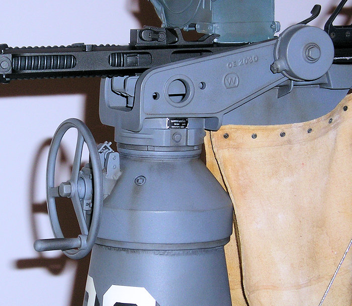
The pedestal crown
was first constructed from basswood in a similar fashion except the pattern was
finish-turned on my Sherline lathe, a step which guarantees that round parts are
truly round. Once I had the basic pattern finished, I then repeated the molding
process and added the mounts for locking handle
 and retention mechanism as well
as the rim and other small details from good old Evergreen sheet styrene to the
resin copy. The crown then was center bored to accept the elevation shaft for
the gun’s yoke.
and retention mechanism as well
as the rim and other small details from good old Evergreen sheet styrene to the
resin copy. The crown then was center bored to accept the elevation shaft for
the gun’s yoke.
The hand wheel was not turned on a lathe because it was bigger than the swing diameter of my Sherline. The wheel was cut from styrene sheet stock of the correct thickness minus the finish layer on my old Dremel jig saw and then carefully finished by hand. Here’s a tip; normally, cutting styrene sheet with a power saw is problematic because the friction heat from the saw blade causes plastic to melt, creating globs of plastic under the cut that make it impossible to keep the work flat on the saw’s table. It also can cause the plastic to close behind the saw blade and weld itself back together as the melted styrene cools. To avoid this problem, I first draw my pattern onto the styrene sheet and then give it a couple of light coats of Testors Dullcoat from the spray can to fix the drawing in place. After that dries, I then trace the pattern to be cut with a good bead of regular motor oil from an oil can onto the styrene before I begin cutting. The oil acts as a cooling medium and also collects the tiny chips of styrene as the blade cuts through the plastic. The oil is easily removed by washing the cut-out part in warm water with dishwashing detergent. I did not mold the hand wheel in resin when it was finished because I only needed one of them! The wheel shaft was constructed from brass rod that fits into a brass bearing in the crown piece.
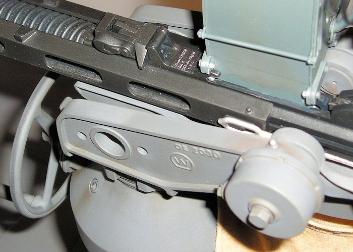
STEP AFTER STEP CONSTRUCTION
 Most of the parts of this build were
fabricated from my drawings in a similar manner; building up each individual
component from styrene stock and making molds to cast parts in polyurethane
resin that were identical and repetitious on the real gun. Scale grease zerks,
bolt and screw heads of differing sizes and types were developed by making one
master pattern, casting several copies of it and then mounting multiple copies
onto a casting block to use as the master for molding and casting dozens of
copies. I mount them on the casting block in such a manner that the resin copies
are easily and precisely removed from the blocks with a single edge razor blade
when needed. I scaled down one 20mm round to 1/6th scale and turned
it from plastic rod on the lathe. Once again, oil is used to keep the plastic
from melting and fouling the tool; in this case WD-40 from a spray bottle. That
gave me the master pattern for the rounds in the magazine and, by cutting the
shell part off the casing and then hollowing out the casing; I had the master
pattern for spent rounds. Yes, there are a bunch of spent rounds in the canvas
collection bag! The gun yoke, cradle and the breach and firing mechanism
assemblies were all created in the same fashion from styrene stock. Brass pins
were used as the axle for the cradle and they mate with brass bearings mounted
in the yoke which allow the model gun to elevate as per the actual weapon.
Most of the parts of this build were
fabricated from my drawings in a similar manner; building up each individual
component from styrene stock and making molds to cast parts in polyurethane
resin that were identical and repetitious on the real gun. Scale grease zerks,
bolt and screw heads of differing sizes and types were developed by making one
master pattern, casting several copies of it and then mounting multiple copies
onto a casting block to use as the master for molding and casting dozens of
copies. I mount them on the casting block in such a manner that the resin copies
are easily and precisely removed from the blocks with a single edge razor blade
when needed. I scaled down one 20mm round to 1/6th scale and turned
it from plastic rod on the lathe. Once again, oil is used to keep the plastic
from melting and fouling the tool; in this case WD-40 from a spray bottle. That
gave me the master pattern for the rounds in the magazine and, by cutting the
shell part off the casing and then hollowing out the casing; I had the master
pattern for spent rounds. Yes, there are a bunch of spent rounds in the canvas
collection bag! The gun yoke, cradle and the breach and firing mechanism
assemblies were all created in the same fashion from styrene stock. Brass pins
were used as the axle for the cradle and they mate with brass bearings mounted
in the yoke which allow the model gun to elevate as per the actual weapon.
MAKING FABRIC MATERIAL LOOK LIKE SCALE CANVAS
A big factor in
scratch building is knowing what you’re capable of…or not. I’m not a seamstress
by any means. I had located fine, tightly woven muslin fabric at A Joanne’s
Fabric store that replicated the appearance of in-scale canvas as a starting
point for the shell collection bag. I could not sculpt the bag from A-B epoxy
because the bag had to be able to flex like the real one for the model gun to
elevate. Judging from the action figure clothing I’ve seen that is machine-sewn,
I knew I’d have to find another way around the barn to use real fabric and still
make the seams look realistic. I developed drawings of the bag f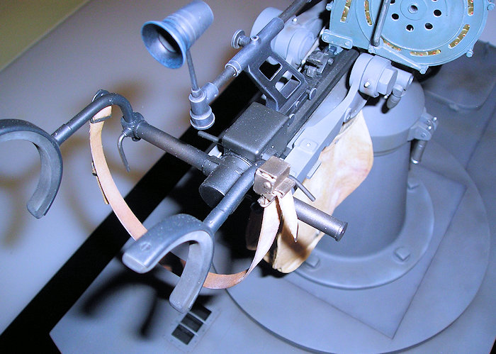 or what would
normally be sewing patterns, and attached them to the fabric using straight
pins. So far, I was taking the traditional approach clothing makers use.
However, instead of sewing the panels together after cutting them out with
surgical scissors, I glued them with a small bead of Aleen’s ‘Stop Fraying’
fabric glue only on where the edges contacted. I also purchased that glue at the
Joanne’s Fabric store. Then, to simulate the seams, I cut pieces of fabric the
size of the distance between the outside edges of the panels and the seamline
and glued them in place. The difference in planes on the finished bag gives an
appearance of a seam line where none actually exists. The eyelets and connector
are resin copies of master patterns I turned on the lathe. Once completed, the
bag was wadded up and soaked overnight in a cup of strong Folgers coffee which
is the best process I’ve found to replicate the color of naval canvas. The
fabric glue truly is water resistant as advertised but I’ll admit I was a tad
nervous! Once dry, the shell collection bag was weathered with pastels and
finished with a couple of coats of Testors Dullcoat. That step is necessary
before meticulously removing tiny errant fibers that are sticking up from the
canvas. The gunner’s back strap was made from the same fabric material by
laminating three layers together with the fabric glue, cut to shape and finished
in the same manner as the bag except it was stained with acrylic and not coffee.
Having access to the U.S. Navy manual for the 20mm allowed me to replicate
accurately the quick-release fitting for the gunner’s back strap.
or what would
normally be sewing patterns, and attached them to the fabric using straight
pins. So far, I was taking the traditional approach clothing makers use.
However, instead of sewing the panels together after cutting them out with
surgical scissors, I glued them with a small bead of Aleen’s ‘Stop Fraying’
fabric glue only on where the edges contacted. I also purchased that glue at the
Joanne’s Fabric store. Then, to simulate the seams, I cut pieces of fabric the
size of the distance between the outside edges of the panels and the seamline
and glued them in place. The difference in planes on the finished bag gives an
appearance of a seam line where none actually exists. The eyelets and connector
are resin copies of master patterns I turned on the lathe. Once completed, the
bag was wadded up and soaked overnight in a cup of strong Folgers coffee which
is the best process I’ve found to replicate the color of naval canvas. The
fabric glue truly is water resistant as advertised but I’ll admit I was a tad
nervous! Once dry, the shell collection bag was weathered with pastels and
finished with a couple of coats of Testors Dullcoat. That step is necessary
before meticulously removing tiny errant fibers that are sticking up from the
canvas. The gunner’s back strap was made from the same fabric material by
laminating three layers together with the fabric glue, cut to shape and finished
in the same manner as the bag except it was stained with acrylic and not coffee.
Having access to the U.S. Navy manual for the 20mm allowed me to replicate
accurately the quick-release fitting for the gunner’s back strap.
THE ‘FOUND OBJECT’ TECHNIQUE HAS ITS PLACE
There are two curved pieces that serve as the mounts for the gunner’s shoulder rests that seem simple enough to replicate but trust me, they’re not. I tried heating plastic rod to bend them to shape, I tried bending brass tubing to shape, I couldn’t locate brass rod in the correct diameter and, just before I pulled out the last three hairs on my balding head, it struck me. Like all modelers who claim to be builders and not collectors, I have an attic full of unbuilt kits! I found a sprue tree that not only was the correct diameter but also had exactly the correct curve on its outside borders! A few cuts with the razor saw, some seam line clean up and…done deal! I don’t use the ‘found object’ technique to simulate detail but sometimes it’s the only way to replicate detail.
BUILDING A 1/6TH SCALE RING SIGHT
The next head
scratcher was the ring sight. The real sight was not a one-piece casting but
rather, constructed from both flat and circular elements. I first photo copied
the pattern of the ring sight from my drawings and, using spray adhesive, glued
it to a piece of flat chipboard soft enough to accept straight pins. I
 then
burnished a piece of laminating plastic over it so it would be impervious to
styrene cement. Next, starting with a plug of resin, I turned a buck on the
lathe with three stepped planes equal to the inside dimensions of the three
rings needed for the sight. The steps leave an edge to align against. Then I cut
the correct width and thickness of the rings from Evergreen styrene stock and
clamped them around the buck with rubber bands, gluing the ends together with
super-fast Plast-I-Weld cement. I then placed the rings in position on the
prepared photo copied pattern and braced them in place with straight pins while
I glued styrene rods and strip stocks in place to complete the sight. What
initially seemed like an insurmountable obstacle actually turned out to be a
relatively simple affair. That doesn’t happen often in scratch building, but it
does happen. The eyepiece was turned on the lathe and then center drilled with
the ‘rubber’ cup piece filed out conically by hand. The most difficult part of
the eyepiece was installing the tiny internal cross hairs, probably because my
fingers are too big and my eyes are too old. If patience is a virtue then I must
be virtuous.
then
burnished a piece of laminating plastic over it so it would be impervious to
styrene cement. Next, starting with a plug of resin, I turned a buck on the
lathe with three stepped planes equal to the inside dimensions of the three
rings needed for the sight. The steps leave an edge to align against. Then I cut
the correct width and thickness of the rings from Evergreen styrene stock and
clamped them around the buck with rubber bands, gluing the ends together with
super-fast Plast-I-Weld cement. I then placed the rings in position on the
prepared photo copied pattern and braced them in place with straight pins while
I glued styrene rods and strip stocks in place to complete the sight. What
initially seemed like an insurmountable obstacle actually turned out to be a
relatively simple affair. That doesn’t happen often in scratch building, but it
does happen. The eyepiece was turned on the lathe and then center drilled with
the ‘rubber’ cup piece filed out conically by hand. The most difficult part of
the eyepiece was installing the tiny internal cross hairs, probably because my
fingers are too big and my eyes are too old. If patience is a virtue then I must
be virtuous.
KNOWING ONE’S LIMITATIONS
As I stated earlier, a scratch builder has to know his own limits. There are two pieces contained in this project that were beyond my capability to produce myself; the gun’s barrel and the slotted front spring retainer piece that is a hallmark of this weapon. It was a hurdle mostly because I don’t own half a million dollars’ worth of machine tools. I don’t own a lathe that can turn a taper, much less reverse tapers, and I don’t have the milling machinery necessary to make slots in tubing. Those two pieces were machined for me by Mike at Maskmachine.com and I’m grateful to him for his patience in interpreting my attempt at dimensioned drawings! He translated my drawings into a CAD file and produced the barrel and front spring retainer from brass stock using a computer controlled lathe. Those parts fit perfectly. He’s a virtuoso with machine tools! I owe a great debt of gratitude to Stephan Sendelbach for finding Mike for me. I blacked the barrel with model railroader’s blackening agent. The recoil springs are made from the correct diameter flux free solder and painted. You can’t use acid to blacken solder!
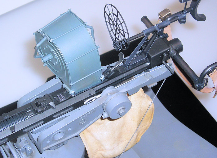
THE DRUM MAGAZINE
I was fortunate in acquiring the US Navy
technical manual for the 20mm Oerlikon that contained in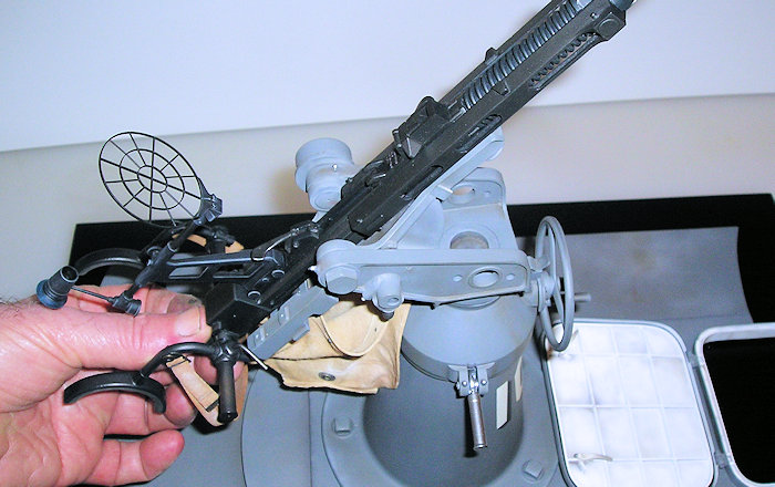 formation necessary to
build a likeness of the drum magazine. There was a beautiful cutaway drawing
contained in it to illustrate how it worked that was invaluable in construction.
I often wondered why there were slots in one end of the magazine and not the
other. The answer, obvious as it may seem, is that there were slots in the rear
face of the magazine so the gunner could tell how many rounds he had left! In
big 1/6th scale that meant the entire interior and working mechanism
of the magazine had to be built because it would be visible upon close
inspection. The magazine was constructed from styrene sheet in very much the
same manner as the real magazine with scaled down thicknesses used. I simulated
the stampings by cutting the patterns from sheet stock and then laminating them
with styrene cement. The protrusion of the axle from the front face of the
magazine is to accept the tool used to wind the spring as the magazine is
loaded. The rounds are all cast in resin using the mold made from my master
pattern. Because the magazine mounts on the weapon at an angle and the diameter
of the front of the magazine is smaller than the rear, projecting the pattern
for the shape of the sheet plastic for the exterior skin of the magazine was
probably the biggest challenge.
formation necessary to
build a likeness of the drum magazine. There was a beautiful cutaway drawing
contained in it to illustrate how it worked that was invaluable in construction.
I often wondered why there were slots in one end of the magazine and not the
other. The answer, obvious as it may seem, is that there were slots in the rear
face of the magazine so the gunner could tell how many rounds he had left! In
big 1/6th scale that meant the entire interior and working mechanism
of the magazine had to be built because it would be visible upon close
inspection. The magazine was constructed from styrene sheet in very much the
same manner as the real magazine with scaled down thicknesses used. I simulated
the stampings by cutting the patterns from sheet stock and then laminating them
with styrene cement. The protrusion of the axle from the front face of the
magazine is to accept the tool used to wind the spring as the magazine is
loaded. The rounds are all cast in resin using the mold made from my master
pattern. Because the magazine mounts on the weapon at an angle and the diameter
of the front of the magazine is smaller than the rear, projecting the pattern
for the shape of the sheet plastic for the exterior skin of the magazine was
probably the biggest challenge.
HATCH AND DEADLIGHT DETAILS
There’s a web site
up there in that ‘cloud’ thingy called PT103.com wherein very detailed graphic
drawings from original Elco blueprints have been developed and that site is a
real treasure trove of detailed inform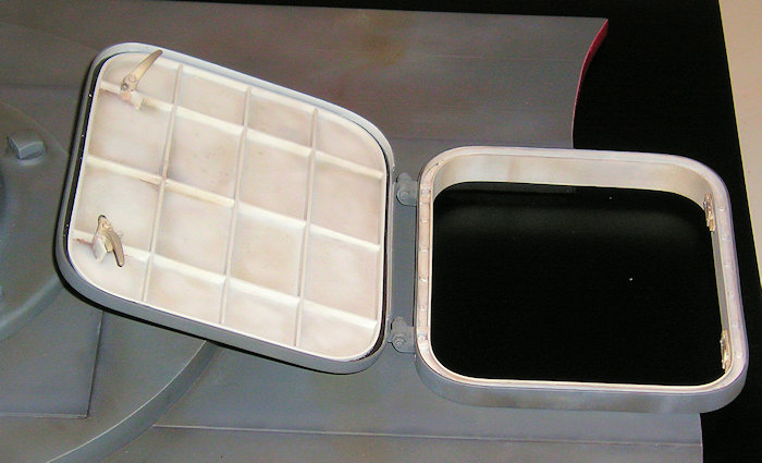 ation on early Elco 80’ PT boats for
modelers. For space considerations, I had decided to keep this display
relatively small and replicate only a section of deck on which to mount the gun.
The length of the gun from end to end and the distance it protrudes from the
mount basically determined how much of the boat’s deck needed to be included in
the display. I made a master pattern for a deadlight frame using reference from
the PT103.com web site and cast a few copies in resin. I did the same for the
hatch, hatch cover and fittings. This allowed me to construct the hatch so that
it opens, closes and locks as per the original as well as showing, in the
cutaway section, the construction of the hatch frame itself. It was fascinating
to learn that the deck hatch cover was not flat on top but rather, had a slight
incline all the way around to aid in water runoff. Most PT boat models show
distinct deck planking patterns that are grossly out of scale. The real boats
had decks that were planked with tight fitting, tongue and groove mahogany
boards and even in 1/35 scale, you would not be able to see the seam lines of
the planking. You will note the seamlines in the deck portion of this display
are very, very faint and I probably overdid it a bit.
ation on early Elco 80’ PT boats for
modelers. For space considerations, I had decided to keep this display
relatively small and replicate only a section of deck on which to mount the gun.
The length of the gun from end to end and the distance it protrudes from the
mount basically determined how much of the boat’s deck needed to be included in
the display. I made a master pattern for a deadlight frame using reference from
the PT103.com web site and cast a few copies in resin. I did the same for the
hatch, hatch cover and fittings. This allowed me to construct the hatch so that
it opens, closes and locks as per the original as well as showing, in the
cutaway section, the construction of the hatch frame itself. It was fascinating
to learn that the deck hatch cover was not flat on top but rather, had a slight
incline all the way around to aid in water runoff. Most PT boat models show
distinct deck planking patterns that are grossly out of scale. The real boats
had decks that were planked with tight fitting, tongue and groove mahogany
boards and even in 1/35 scale, you would not be able to see the seam lines of
the planking. You will note the seamlines in the deck portion of this display
are very, very faint and I probably overdid it a bit.
CONSTRUCTING THE BASE
I constructed the base in the same manner as all the bases I build for my large scale figure projects. I frame the base with 1//2” hardwood with a cut-out that will accept the mount for the nameplate and with the top made of ¼” plywood similarly notched. The angled panel for the nameplate is made of basswood and inserted into the front of the wooden frame. I then laminate the entire base with 1/8” styrene sheet cut to shape and scored on one side. Each lamination panel is attached to the wood with 5 minute epoxy smeared completely over the scored side. After it is cured for a day or two, I sand it smooth and fill any imperfections or ripples with Bondo surfacing putty and then spray it with a rattle can the color I wish. Another special thank you goes to to Fritz (the Headless Hearseman) for turning my art for the title into a three-dimensional metal name plate; excellent work on his part, as usual. The nameplate is attached to the base before painting the base color and the details painted by hand later.
| COLORS & MARKINGS |
I discovered quite by
accident a few years ago, that Krylon #1318 All Purpose Gray Primer in the spray
can is a perfect match for the Navy gray Elco used on their PT103 series upper
decks and fittings in 1/6th
 scale. It also has the advantage of being
fast drying and cures to a very permanent and durable finish. I decanted that
paint from the spray can and airbrushed it through my Badger Sotar 20/20.
Because the color of the drum magazine varied considerably from manufacturer to
manufacturer, sometimes even painted black, I decided to use a different shade
of navy gray with a more greenish cast to add a little variation of color to the
display. I also decided that because I was depicting the anti-aircraft gun
position as it was delivered by Elco, I would keep the weathering to a minimum.
I mostly used spot washes and pastels to indicate a minimum of wear and tear
with the harshest weathering obvious on the deck and hatch areas. I could find
nothing in my reference to indicate that either Elco or US Navy personnel
painted the lubrication points of the gun and mount red for quick identification
which was the practice in the Marine artillery units I was in. To be safe, I
left the lube points alone, only painting the grease zerks with Testors ‘chrome’
from the small bottle. I figured that since the drum magazine would have seen
considerable man handling, skinning up the paint a bit wouldn’t hurt. For those
of you who have met the love of my life, Minerva, at trade shows, you know she
has a strong influence on my work. It was her idea to add a few footprints on
the deck and it definitely added life to the effect. Thanks Hon. I cut masks the
shape of left and right 1/6th scale shoe soles and applied the ‘foot
prints’ with pastel pigment powders. The panels in the deadlight frames are cut
from 1/32” clear acrylic sheet.
scale. It also has the advantage of being
fast drying and cures to a very permanent and durable finish. I decanted that
paint from the spray can and airbrushed it through my Badger Sotar 20/20.
Because the color of the drum magazine varied considerably from manufacturer to
manufacturer, sometimes even painted black, I decided to use a different shade
of navy gray with a more greenish cast to add a little variation of color to the
display. I also decided that because I was depicting the anti-aircraft gun
position as it was delivered by Elco, I would keep the weathering to a minimum.
I mostly used spot washes and pastels to indicate a minimum of wear and tear
with the harshest weathering obvious on the deck and hatch areas. I could find
nothing in my reference to indicate that either Elco or US Navy personnel
painted the lubrication points of the gun and mount red for quick identification
which was the practice in the Marine artillery units I was in. To be safe, I
left the lube points alone, only painting the grease zerks with Testors ‘chrome’
from the small bottle. I figured that since the drum magazine would have seen
considerable man handling, skinning up the paint a bit wouldn’t hurt. For those
of you who have met the love of my life, Minerva, at trade shows, you know she
has a strong influence on my work. It was her idea to add a few footprints on
the deck and it definitely added life to the effect. Thanks Hon. I cut masks the
shape of left and right 1/6th scale shoe soles and applied the ‘foot
prints’ with pastel pigment powders. The panels in the deadlight frames are cut
from 1/32” clear acrylic sheet.
| CONCLUSIONS |
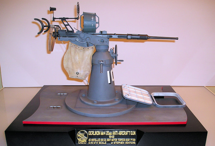
Well, that’s just about it. This project was certainly frustrating at times and sometimes, as in all modeling projects, the light at the end of the tunnel appeared dim indeed. However, upon completion of a scratch built model you are rewarded with a one-of-a-kind piece that you can truly say is your own work. There’s nothing more rewarding than that feeling and I would highly recommend giving scratch building a go. This model earned a gold medal at the 2015 Military Miniature Society of Illinois show and was awarded the ‘Butch O’Hare Award –Best US Navy-‘and ‘Best In Show’ at the 2015 International Plastic Modeler’s Society Butch O’Hare chapter competition. I hope you enjoy this piece.
January 2016
Stephen Venters Copyright ModelingMadness.com If you would like your product reviewed fairly and fairly quickly, please
contact
the editor or see other details in the
Note to
Contributors.