Dragon 1/35 T-28 Super Heavy Tank
| KIT #: | 6750 |
| PRICE: | $69.95 SRP |
| DECALS: | Several options |
| REVIEWER: | Dale Rannals |
| NOTES: | New tool kit |
| HISTORY |
The rejected M6A2E1 project proposed that a limited
number of assault vehicles be improvised by modifying the stock of T1E1 heavy
tanks. However, a far more extensive program to develop a heavily armed and
armored combat vehicle had been initiated in September 1943. Studies by the
Ordnance Department indicated that such a vehicle would be required after the
invasion of Europe to penetrate heavily fortified areas such as the German West
Wall. The original concept proposed mounting the new
 105mm gun
T5E1 in a tank with the equivalent of 8 inch frontal armor using the electric
drive system developed for the T1E1 heavy tank and the medium tank T23. The high
velocity 105mm gun had excellent penetration performance against concrete and
when installed in a heavily armored chassis was expected to be extremely
effective in reducing heavy fortifications. The Chief of Ordnance proposed that
25 of the new tanks be produced and estimated that they could be completed in
eight to twelve months. Such a schedule was expected to make them available in
time for operations in Europe. The Army Ground Forces did not agree and
recommended that only three pilot models be constructed and that the electric
drive be replaced by a mechanical transmission. After a conference with the
various parties concerned, the Army Service Forces in March 1944 authorized the
procurement of five vehicles, designating them as the heavy tank T28. The
original specification was modified to increase the frontal armor to 12 inches
raising the estimated combat weight to 95 tons.
105mm gun
T5E1 in a tank with the equivalent of 8 inch frontal armor using the electric
drive system developed for the T1E1 heavy tank and the medium tank T23. The high
velocity 105mm gun had excellent penetration performance against concrete and
when installed in a heavily armored chassis was expected to be extremely
effective in reducing heavy fortifications. The Chief of Ordnance proposed that
25 of the new tanks be produced and estimated that they could be completed in
eight to twelve months. Such a schedule was expected to make them available in
time for operations in Europe. The Army Ground Forces did not agree and
recommended that only three pilot models be constructed and that the electric
drive be replaced by a mechanical transmission. After a conference with the
various parties concerned, the Army Service Forces in March 1944 authorized the
procurement of five vehicles, designating them as the heavy tank T28. The
original specification was modified to increase the frontal armor to 12 inches
raising the estimated combat weight to 95 tons.
The proposed tank was a low silhouette vehicle without a turret. The
105mm gun T5E1 was to be mounted in the front of the hull with a traverse of 10
degrees to the right and left of center and an elevation range of -5 to +20
degrees.
The power package in the T95 was essentially the same as in the M26
Pershing tank, although the weight of the new vehicle was more than twice that
of the latter. To handle the T95, the 500 horsepower Ford GAF engine and the
torqmatic transmission required a final drive gear ratio that reduced the
maximum vehicle speed to about eight miles per hour. In fact, the maximum
recommended sustained speed was seven miles per hour at 2600 rpm. The great
weight of the vehicle also required considerable ingenuity in design to reduce
the ground pressure to an acceptable level. This objective was achieved by the
use of two sets of tracks on each side. The outer set, along with the four inch
thick armor side skirts, could be removed and towed behind the vehicle when
operating on a hard surface. Removing the outer tracks also reduced the overall
width from 179 1/2 inches to 124 inches permitting rail transportation. At
Aberdeen, an inexperienced four man crew removed the outer tracks under field
conditions in four hours on their first
 try. An
equal amount of time was required to reassemble them onto the vehicle. By the
third try, the same team had reduced the time to remove or replace the outer
tracks to 2 1/2 hours.
try. An
equal amount of time was required to reassemble them onto the vehicle. By the
third try, the same team had reduced the time to remove or replace the outer
tracks to 2 1/2 hours.
A crew of four was
carried with the driver and gunner in the front hull on the left and right of
the cannon respectively. The loader was at the left rear of the fighting
compartment and the commander at the right rear behind the gunner. The driver
and the commander were each provided with a vision cupola. A ring mount for a
.50 caliber machine gun was installed around the commanders cupola. It could be
used only with the commander standing in the open hatch and was the only
secondary armament on the vehicle, except for the individual crew weapons. The
gunner was equipped with a telescope alongside the cannon and a periscopic sight
in the hull roof.
On 7 February
1945, a memorandum from the Chief of Ordnance requested that the T28 be
re-designated as the 105mm Gun Motor Carriage T95 because the cannon was not
turret mounted and because of its limited secondary armament. Because of the
pressure of the wartime production program as well as the size and weight of the
proposed vehicle, there was some difficulty in finding a facility to manufacture
the five pilots. However, the Pacific Car and Foundry Company agreed to take on
the project. They were supplied with the basic vehicle design as well as
detailed information on the gun mount and the horizontal volute spring
suspension. Final design work began immediately. The first front end casting was
delivered on 20 June and welding was completed on the first hull in August 1945.
After the end of
the war in the Pacific, the number of pilots was reduced from five to two with
number 1 being shipped to Aberdeen Proving Ground on 21 December 1945 followed
by number 2 on 10 January 1946. The first pilot was used for engineering tests
at Aberdeen, and the second was transferred first to Fort Knox and later to the
Engineer Board at Yuma, Arizona where it was used for testing floating bridges.
 The
heavily armed and armored T95 did not quite fit any of the usual categories for
U. S. Army fighting vehicles. For example, tanks were expected to carry their
armament in fully rotating turrets and self-propelled guns usually were lightly
armored to achieve maximum mobility. (It has been argued that it was neither a
super-heavy tank nor a self-propelled gun, but that it was in fact a very heavy
tank destroyer, more accurately as an American version of one of the German
Jagdpanzer-style tank destroyers, intended to take on German heavy tanks.)
The T95 did not meet either of these criteria and in
June 1946, there was another name change. At that time, OCM 30758 re-designated
the vehicle as the Super Heavy Tank T28. It then was considered that the
combination of heavy firepower and heavy armor was more appropriate for a tank
than a gun motor carriage.
The
heavily armed and armored T95 did not quite fit any of the usual categories for
U. S. Army fighting vehicles. For example, tanks were expected to carry their
armament in fully rotating turrets and self-propelled guns usually were lightly
armored to achieve maximum mobility. (It has been argued that it was neither a
super-heavy tank nor a self-propelled gun, but that it was in fact a very heavy
tank destroyer, more accurately as an American version of one of the German
Jagdpanzer-style tank destroyers, intended to take on German heavy tanks.)
The T95 did not meet either of these criteria and in
June 1946, there was another name change. At that time, OCM 30758 re-designated
the vehicle as the Super Heavy Tank T28. It then was considered that the
combination of heavy firepower and heavy armor was more appropriate for a tank
than a gun motor carriage.
Regardless of the
name, the T28 (T95) was under test at Aberdeen Proving Ground until late 1947,
primarily to evaluate the durability of components on such a heavy vehicle. A
total of 541 miles of operation was completed consisting of 128 miles on roads
and 413 miles on gravel. Needless to say, the mileage accumulated slowly because
of the low normal operating speed of five to six miles per hour and the low
priority assigned to the project. Work was terminated before completion of the
program in compliance with a War Department policy to discontinue development on
combat vehicles in the 100-ton class. One of the T28 (T95) pilots is on display
today in the collection of the Patton Museum at Fort Knox, Kentucky.
| THE KIT |
Previously the only way to have one of these beasts in your collection was a
very nice but pricey resin kit from Accurate Armour -
kit # Nr. K098.
Dragon now gives us an injection molded option.
Dragon's T95 kit arrives in a very large box adorned with a nice picture
of one of these during testing (I presume anyway).
The box back has cad drawings of all the kits features.
Opening the box shows it is filled to the brim with
plastic, all done in Dragon's normal gray styrene.
Each sprue is typical of Dragons flash-free detail, and
there are lots and lots of sprues.
You will have lots of parts parts left over, as many
sprues have only a
 few parts
used from them.
Typical of Dragon, they include whole sprues from other kits just
to use a part or two from them.
I'm sure this is a cost-effective way to do things, and
I don't mind having the spare parts at all, but it can cause some confusion.
I will explain in a bit.
few parts
used from them.
Typical of Dragon, they include whole sprues from other kits just
to use a part or two from them.
I'm sure this is a cost-effective way to do things, and
I don't mind having the spare parts at all, but it can cause some confusion.
I will explain in a bit.
There are over 700 parts in total, including somewhere around 33 sprues,
both small and (mostly) large.
Also included are a small PE fret of brass, 8 sections
of Dragon's DS (deformable styrene) tracks, 32 small metal springs for the
suspension bogies, and a section of metal wire for the tow cables.
Instructions take the form of a large fold-out
containing 12 construction steps, printed in their normal blue and black.
Sprue layouts are included and it is wise to pay
attention to this as many of the sprue have the same letter code because they
are from different kits.
Decal sheet is very small and includes the serial number
of the first prototype, but also additional numbers to make any serial you
desire.
I am glad Dragon included their DS tracks, as I am not a fan of individual link types. But this time it wasn't so easy, as there are about 400 little tiny track guides to install on them.
| CONSTRUCTION |
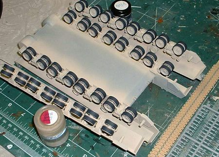
Construction started with the suspension.
And there are lots of it too.
I hadn't really thought about it until until I was
looking at the sprues, that 90% of this kit is suspension.
And it was going to take some tedious work. I started
out by assembling all the various guide wheels.
I put each set in labeled zip-lock bags so I wouldn't
forget what went where later on.
Then I started on the wheel bogies.
Each of these very detailed assemblies contains 23 parts
and there are 16 bogies to make.
In each, one needs to capture two metal
 springs
between two plastic retainers ..... amazingly I did not lose a single spring.
These are designed to articulate if carefully assembled,
but as I had no such ambitions everything was glued solid.
Once I had all these assembled I attached them all to
the hull and side skirts, then painted these areas a desert sand color (ANA
Sand, to be exact).
I needed to paint here before I put the tracks on, and I
needed to put the tracks on before I attached the side skirts to the hull. So I
now needed to attack the tracks.
Eight
sections of DS tracks needed individual track guides installed, about 50 per
section.
I did this in two 2-hour sessions, and it was mind-numbing at best.
I did manage to lose several of the tiny pieces,
fortunately many spares are included.
Now for this builds major screw up, I had just finished
up the first two track sections when I realized I was gluing the guides on the
wrong side!
DOH!!
Well, I wasn't thrilled about re-doing 100 tiny bits
and, somewhat fortunately, they were quite reluctant to part from the tracks, so
I, um, rolled with it.
I figured with those heavy side skirts and four tracks I
should be able to hide most of this.
I decided to glue each flubbed section to a correct
section, then put that track on the inside of each pair with most of the bad
area up underneath the skirt.
Only a small portion will show at the rear.
So...........
springs
between two plastic retainers ..... amazingly I did not lose a single spring.
These are designed to articulate if carefully assembled,
but as I had no such ambitions everything was glued solid.
Once I had all these assembled I attached them all to
the hull and side skirts, then painted these areas a desert sand color (ANA
Sand, to be exact).
I needed to paint here before I put the tracks on, and I
needed to put the tracks on before I attached the side skirts to the hull. So I
now needed to attack the tracks.
Eight
sections of DS tracks needed individual track guides installed, about 50 per
section.
I did this in two 2-hour sessions, and it was mind-numbing at best.
I did manage to lose several of the tiny pieces,
fortunately many spares are included.
Now for this builds major screw up, I had just finished
up the first two track sections when I realized I was gluing the guides on the
wrong side!
DOH!!
Well, I wasn't thrilled about re-doing 100 tiny bits
and, somewhat fortunately, they were quite reluctant to part from the tracks, so
I, um, rolled with it.
I figured with those heavy side skirts and four tracks I
should be able to hide most of this.
I decided to glue each flubbed section to a correct
section, then put that track on the inside of each pair with most of the bad
area up underneath the skirt.
Only a small portion will show at the rear.
So...........
The
sections were glued together (two per track) and painted a very dark (almost
black) gray.
I did not bother to weather the tracks now, I decided to save
this for the end and, since this machine is heavily skirted, just weather what
can be seen.
For the same reason, I did not bother to paint the guide roller
rubber portions that were up under the skirts.
Would be hard to see them if you tried, so why waste the
paint?
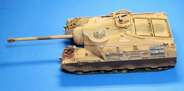
One of options of this kit is to leave the side skirts off and towed
behind.
Though I think that would make for a very interesting diorama, I decided
to build her all bolted together.
So the skirts were glued on after the
tracks were attached.
The front part of each skirt has a nice attachment lip,
the rear two-thirds do not.
So I attached each side, gluing only the front portion
and letting it dry.
Then I glued the rear of each using tape and clamps to
get the best join I could.
No worries about the seam, as it is there on the real
thing 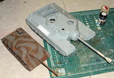 obviously,
but I didn't want major gaps either.
The body was left to dry thoroughly.
obviously,
but I didn't want major gaps either.
The body was left to dry thoroughly.
The main gun is a simple affair, it allows for elevation but not for
transverse.
The elevation pivot is somewhat too loose for the long aluminum
barrel, so mine was a bit droopy.
I ended up gluing it in a more battle-worthy position.
The copulas were assembled but left off, I needed to
paint these and then attach the clear vision ports, then glue them on.
Adding all the little bits was
frustrating for me, for silly reasons.
I looked for a long time to try to find the headlamps ….
part
C2
…... I studied sprue C for a long time and found the right numbered
part, but it wasn't a headlamp.
It took a while, but I finally realized I was looking at
part C2, when I needed to find part
C2
(it was denoting sprue
C
[blue
ink]
whereas I was looking at sprue C [black ink] on the instruction page).
A disadvantage of using sprues from other kits that are
labeled the same.
Sprue B also has a blue and black, FYI.
Also, be aware that the Q sprues are cut up into
sections (so everything fits in the box) so you need to look at them all to find
the correct parts there too.
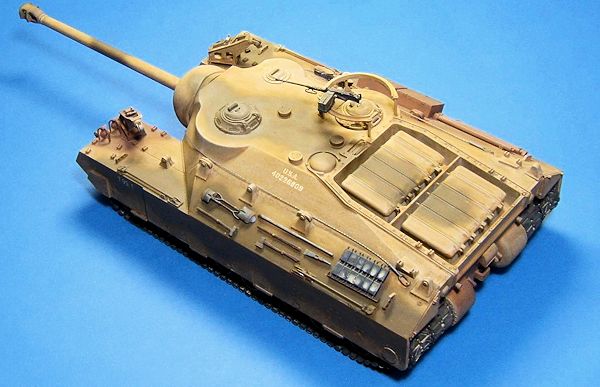
My other bit of frustration was dealing with the storage boxes on the
hull side.
Dragon includes these as PE.
Why exactly?
I don't mind PE, but only when it serves a purpose.
Boxes can be easily injection molded and would look
every bit as good.
I tossed the PE boxes in the trash and made my own from
Evergreen plastic sheet.
| COLORS & MARKINGS |
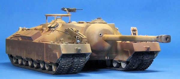
I
decided on a late war tropical camo for this one, and started with Model Master
ANA Sand
I then sprayed areas using olive drab and, interestingly enough, Panzer
Red, f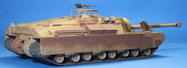 or
it was very close to the hue I wanted.
What little decals there are were applied next; I did
not bother gloss-coating the kit for this, I just applied a drop of Future under
each decal to prevent silvering.
I then
went over everything with a black oil wash to bring out the details, followed by
numerous raw umber washes.
Some Tamiya weathering pastels were brushed around to
highlight raised areas.
The tracks got the same umber washes, along with some
highlighting of steel and a final sand wash consisting of Tamiya pastels and
water (and a drop of dish washing liquid to break up the surface tension).
or
it was very close to the hue I wanted.
What little decals there are were applied next; I did
not bother gloss-coating the kit for this, I just applied a drop of Future under
each decal to prevent silvering.
I then
went over everything with a black oil wash to bring out the details, followed by
numerous raw umber washes.
Some Tamiya weathering pastels were brushed around to
highlight raised areas.
The tracks got the same umber washes, along with some
highlighting of steel and a final sand wash consisting of Tamiya pastels and
water (and a drop of dish washing liquid to break up the surface tension).
| CONCLUSIONS |
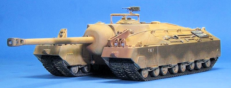
A monster of a kit, that's for sure.
Sitting next to other tanks, its size is certainly
impressive.
An easy build it is not.
It's not a hard build either, but the sheer number of
suspension components, along with the individual guides on the tracks, make it a
tedious build.
But if one is interested in armor prototypes and oddities, the
result is certainly worth it.
| REFERENCES |
The internet
March 2013
If you would like your product reviewed fairly and fairly quickly, please contact the editor or see other details in the Note to Contributors.