Monogram 1/48 A-10A Thunderbolt II
|
KIT # |
5505 |
|
PRICE: |
$16.95 |
|
DECALS: |
One aircraft |
|
REVIEW : |
|
|
NOTES: |
Kit updated with LASTE Mods |
|
THE KIT |
Monogram has a knack for capturing the true likeness of an aircraft in a
scale model. This is definitely true for the 1/48 scale A-10A. Despite of the
age of a majority of the Monogram kits, some have exceptionally good fitting
parts while others provide a challenge. The latter is also true for A-10A kit.
The fit is so atrocious that I can’t fathom how some people can say they can
built this model without loosing a raised rivet or raised panel line and still
achieve smooth seamless joints! If there were a test for modeling skill, I would
have to 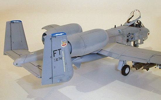 say this kit is the final exam for basic finish. But despite some of the
kit’s failings, an intermediate level modeler can produce a fine looking model
of the ultimate tank killer.
say this kit is the final exam for basic finish. But despite some of the
kit’s failings, an intermediate level modeler can produce a fine looking model
of the ultimate tank killer.
This is the second Monogram A-10 that I have built; the first one in 1989 built straight out of the box. The first have since gone to the city bone yard after proving low thrust to weight ratio is not conducive to flight. So armed with knowledge of what to expect from this kit and being totally motivated by the new A-10 resin cockpit from Black Box, I dived into my second attempt.
The kit parts came in dark green styrene with standard raised panel lines. The fuselage, stabilizer, and fin have delicate and beautiful raised rivet details. An outstanding feature of the kit is the fine molding on the landing gears, wheels, nose gear bay, and the beautifully shaped clear windshield and canopy. Molding flash are found on some parts.
|
CONSTRUCTION |
My philosophy for building a Monogram kit is the panel lines must be rescribed. Using the original raised panel lines and the Squadron A-10 Walk Around book, I begin the work. One of the "secrets" to scribing panel lines is to sand off only 80% of the raised lines and use the remaining outline as the guide to scribing. Scribing was done using a sewing needle and Dymo tape as the guide for drawing the straight lines. Rivet holes were drilled out using a #77 model drill bit which you can get at a fine hobby shop like Uncle Bills in Calgary. This took about 2 weeks to complete.
Cockpit
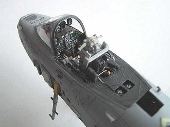 The Black Box cockpit is fabulous! A must have for this kit. Although the
basic kit cockpit is quite good, the seat really needs a resin replacement. The
seat of the kit’s Aces II seat is molded integral with the cockpit floor and
cutting it out is a mess. So why not splurge and get a complete improved
cockpit. Typical with Black Box, fitting in the cockpit is an exercise in
patience. Dry fitting is an absolute necessity to achieve good fit. Start first
by shaving off, with a No. 11 blade, the kit fuselage console sidewall per Black
Box’s instruction. Don’t over shave and keep doing dry fitting until perfect.
The resin sidewall comes with the cockpit heater pipes typical of A-10s in the
80s. If you are doing a modern A-10 like I am, shave off these heater pipes. It
is such a shame to shave off these fabulous details. I didn’t do this on mine
because I found this out after I finish the cockpit. In order for the nose gear
bay to fit underneath the resin cockpit, cut and sand all the resin off the side
and bottom of the cockpit tub. I do mean ALL. This will leave you with a very
thin floor. Be careful not to sand right through the tub.
The Black Box cockpit is fabulous! A must have for this kit. Although the
basic kit cockpit is quite good, the seat really needs a resin replacement. The
seat of the kit’s Aces II seat is molded integral with the cockpit floor and
cutting it out is a mess. So why not splurge and get a complete improved
cockpit. Typical with Black Box, fitting in the cockpit is an exercise in
patience. Dry fitting is an absolute necessity to achieve good fit. Start first
by shaving off, with a No. 11 blade, the kit fuselage console sidewall per Black
Box’s instruction. Don’t over shave and keep doing dry fitting until perfect.
The resin sidewall comes with the cockpit heater pipes typical of A-10s in the
80s. If you are doing a modern A-10 like I am, shave off these heater pipes. It
is such a shame to shave off these fabulous details. I didn’t do this on mine
because I found this out after I finish the cockpit. In order for the nose gear
bay to fit underneath the resin cockpit, cut and sand all the resin off the side
and bottom of the cockpit tub. I do mean ALL. This will leave you with a very
thin floor. Be careful not to sand right through the tub.
 The resin Aces II seat is beautiful and the only addition I needed to make is
to add the launch rail cross brace near the top using 0.80" styrene
C-Channel from Evergreeen. I made the oxygen hose on top of the starboard
console by winding thin brass wire over a tightly stretched thin brass wire.
Control levers were added using any left over photo edge scraps that resemble
levers. The tips of which were dipped into thicken cyanoacrylate and when dried
dipped into thicken acrylic model paint. At this point, I cut off the kit HUD
mount and store it for safe keeping until needed.
The resin Aces II seat is beautiful and the only addition I needed to make is
to add the launch rail cross brace near the top using 0.80" styrene
C-Channel from Evergreeen. I made the oxygen hose on top of the starboard
console by winding thin brass wire over a tightly stretched thin brass wire.
Control levers were added using any left over photo edge scraps that resemble
levers. The tips of which were dipped into thicken cyanoacrylate and when dried
dipped into thicken acrylic model paint. At this point, I cut off the kit HUD
mount and store it for safe keeping until needed.
Here’s a tip. I found that by lightly trimming the resin instrument panel sides I was able to this piece in after I glue in the cockpit tub and assembled the fuselage. This provided me with two benefits: 1) I was able to use the open instrument panel space to throw in more lead weights into the nose and, 2) by putting in the panel in last, I can align the panel to fit both the tub and the kit dash.
Nose Gear bay
Using the photos in the Squadron Walk Around book, I detailed the already detailed nose gear bay using brass wires to simulate the piping. I only needed to add 5 pieces of piping to the sidewalls. I used brass wires to simulate the pipes. Paint the gear bay with Aircraft Grey before gluing it in to the fuselage. I like to accentuate raised details by spraying on a darken base color over the raised details and then dry brush a lighten base color over it.
Nose weight
The A-10 is a tail-heavy plane. To determine how much weight is needed, tape the fuselage, wing, tail planes, and landing gears together and keep taping lead fishing anchors to the nose until the nose gear sits firm to the ground. Epoxy in as many lead fishing anchors as you can into both sides of the nose.
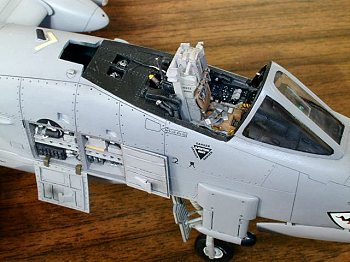
Open Panels
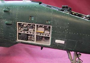 When I started this project, I decided to open the starboard avionics and
circuit breaker panels to add some interest to the model. Following the scribed
panel lines in this area, I cut out the opening. Evergreen 0.03" thick
styrene sheets were used to make the enclosing walls. I sized the walls so that
it will fit snug inside the fuselage cut out to support the thin styrene framing
that will be added after the model is finish. 0.08" C-channel is used to
make the horizontal bracing. Holes were drilled into the C-channel to simulate
the lightening holes. The fuse box and other boxes were cut from scrape resin
bits. Never throw anything away. Wiring was made from thin brass wire.
When I started this project, I decided to open the starboard avionics and
circuit breaker panels to add some interest to the model. Following the scribed
panel lines in this area, I cut out the opening. Evergreen 0.03" thick
styrene sheets were used to make the enclosing walls. I sized the walls so that
it will fit snug inside the fuselage cut out to support the thin styrene framing
that will be added after the model is finish. 0.08" C-channel is used to
make the horizontal bracing. Holes were drilled into the C-channel to simulate
the lightening holes. The fuse box and other boxes were cut from scrape resin
bits. Never throw anything away. Wiring was made from thin brass wire.
The two hanging panels were made from 0.01" thick styrene sheets. To simulate ribbings on the panels, I used 0.015"x 0.04"strips to build it up. The air scoops were cut from 0.01" sheet and folded to form the scoops. The skills I learned from making paper toys when I was a kid really help here.
General Assembly
 After fitting in the nose gear bay and starboard avionics bay, the fuselage
is at last glued together. At the same time, take care in aligning the Black Box
cockpit to the opening in the fuselage. I use thin cyanoacrylate to quickly hold
it in place once I got the alignment. The instrument panel was then glue in.
Despite my best effort, the resin instrument panel sits a bit higher than the
kit dash. I solved this problem by making a styrene filler piece that lay over
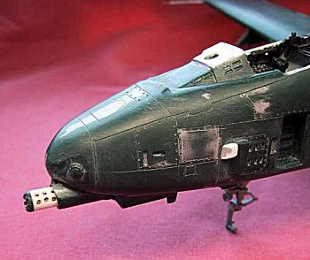
the dash and HUD area (see close up of the unpainted nose section). This filler
was sanded to merge with the rest of the dash and thus obtained a perfect fit.
After fitting in the nose gear bay and starboard avionics bay, the fuselage
is at last glued together. At the same time, take care in aligning the Black Box
cockpit to the opening in the fuselage. I use thin cyanoacrylate to quickly hold
it in place once I got the alignment. The instrument panel was then glue in.
Despite my best effort, the resin instrument panel sits a bit higher than the
kit dash. I solved this problem by making a styrene filler piece that lay over
the dash and HUD area (see close up of the unpainted nose section). This filler
was sanded to merge with the rest of the dash and thus obtained a perfect fit.
The wing and the stabilizers were glued into place using liquid cement.
Liquid cement takes about a minute to set thus giving me enough time to set the
alignment for these parts. The fit of the wing to the fuselage is very bad. I
find that no matter how much shaving I do to the wing root, I just can’t get
them to fit well at the top and bottom of the wing. I tried to minimize the gap
at the top of the wing and thus accepted larger gaps to the bottom wing joint.
The large gaps were filled in with cyanoacrylate. Large wing root gap is not
 the
only problem, the wings will not glue in exactly perpendicular to the fuselage.
I don’t think there’s much you can do about this. You just have to fudge it.
the
only problem, the wings will not glue in exactly perpendicular to the fuselage.
I don’t think there’s much you can do about this. You just have to fudge it.
The engine intake and the compressor blades are molded as one piece. This is pretty bad design. Worst yet, this piece does not fit flush with the engine nacelle intake lip. After gluing this piece into the engine nacelle and taking cares to align it so that I get the minimum amount of misfit. I shaved and sand flush this piece to the nacelle intake lip. Liberal amount of putty was used at this joint to ensure seamless joint.
Plenty of sanding and putty is needed on the fuselage joints. To make sanding easier, I cut off all the fuselage antenna and store them for later restoration. There are sink marks near the joint on both top and bottom of the fuselage. The worst joint is the bottom fuselage joint where the joint dipped and raised along the joint. This is why I challenge anyone to prove their claim that they can build this joint without loosing the rivets and still get a 100% perfect seamless joint.
The air intake scoop located atop the fuselage between the engine nacelles was drilled out and a sharp No. 11 blade was used to refine the openings. I break out the gap filling cyanoacrylate and putty again to glue the engine nacelle to the fuselage. This joint leaves a 1/16" gap everywhere no matter how I align it.
 The Monogram kit was missing a small gun exhaust cover that is located under
the windshield on the port side. The small cover was made from pieces cut from
styrene sheets and glued together.
The Monogram kit was missing a small gun exhaust cover that is located under
the windshield on the port side. The small cover was made from pieces cut from
styrene sheets and glued together.
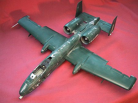
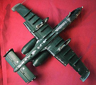
As evident from the pictures, mucho putty was used for this kit to achieve a 100% seamless joints. Sanding and putty work took over two weeks to complete. To check the progress of the seam sanding and putty work, I hold the piece under a light and view it at different angles. The other key to good seam work is to do 80% of the work using various grades of wet sand paper; work from course to ultra fine. Good seam work is basic to plastic modeling. You can never spend enough time on this aspect of the work. I have seen so many models with good paint jobs that lost at model shows only because the basic seam work was not good enough.
More sanding and putty is required for the huge gap at the bottom wing section joint at the wing tips. Even more putty is required at the bottom wing joint on the flaps. I swear I used up half a tube of Tamiya putty.
After filling in the major seams, I rescribed all the missing or filled in panel lines back in. This includes the wing joint and anywhere else where panel lines need to connect. This is another weak area I notice some modelers have. I have seen models with good paint job, even good seam work, but the builder just didn’t bother to go back and fix up the sanded over seams! When do panel lines on the real aircraft just suddenly disappears? It is really disappointing to see some Judges don’t pick up basic thing like this and awards a first place to models with this kind of defect.
 The kit came with the speed breaks in the open position. I much prefer a
clean look on the wing so I cut the speed breaks off and glue them in the close
position. The only trick here is to do a lot of shaving on the trailing edges of
these speed breaks to fit.
The kit came with the speed breaks in the open position. I much prefer a
clean look on the wing so I cut the speed breaks off and glue them in the close
position. The only trick here is to do a lot of shaving on the trailing edges of
these speed breaks to fit.
The kit gun barrel cover just doesn’t cut the mustard. So, I scratch built the gun cover using 3/16" dia. styrene tube and reused the kit’s gun cover plate. I carefully layout the hole pattern on the gun cover and dilled. Though it is not so evident on the photos, I did glued in brass wire to represent the gun barrels inside the cover.
Hydraulic lines on the landing gears were represented using thin brass wires.
The kit pitot tube on the starboard wing tip is way too weak. I replaced the kit part with aluminum tube and a piece of brass wire for the tip. The tip of the tube where it meets the wire tip was 50° tapered. When done the new tube was glued in a pre-drilled hole in the wing tip using cyanoacrylate. There, the landing gears will fall apart long before this pitot tube will break off.
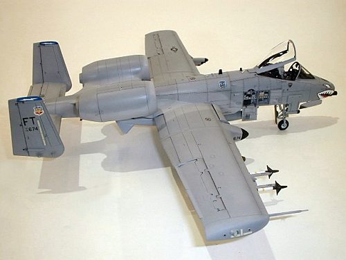
LASTE mods
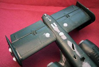 All modern A-10s have been upgraded with the LASTE modifications. I
incorporated the mods to the model by scratch building all the radar blisters
and mods. The blisters on the rudder fins were made from three layers of
0.03" thick styrene sheets and sanded to shape. I photocopy a large image
of the rudder fin from the Squadron Walk Around book. This image is scaled down
using a photocopier to exactly the same size as the kit rudder fin. The image of
the blisters on this scaled image was then used as the template to scratch built
the model blisters.
All modern A-10s have been upgraded with the LASTE modifications. I
incorporated the mods to the model by scratch building all the radar blisters
and mods. The blisters on the rudder fins were made from three layers of
0.03" thick styrene sheets and sanded to shape. I photocopy a large image
of the rudder fin from the Squadron Walk Around book. This image is scaled down
using a photocopier to exactly the same size as the kit rudder fin. The image of
the blisters on this scaled image was then used as the template to scratch built
the model blisters.
Thanks to a suggestion from a fellow web surfer on the ARC web site, I made the blisters on the bottom of the stabilizers from the clear lenses for the Maverick missiles. The crown of the lens was sanded flat and a piece of square styrene glued on top of it to form the cover for the blister.
The modern A-10s have 2 fuel vent pipes sticking atop of the fuselage, located between the antenna blade and the formation light. I made these vents out of 0.04" dia. styrene rods and the holes drilled out.
The big circular antenna at the bottom of the rear fuselage was made from a 3/16" dia. styrene tube with styrene cover plate and styrene sheet antenna blade.
 The front and rear radar warning antenna covers were removed from most A-10s
long ago. So, these covers, one at the rear fuselage and one at the nose, were
cut out and putty over.
The front and rear radar warning antenna covers were removed from most A-10s
long ago. So, these covers, one at the rear fuselage and one at the nose, were
cut out and putty over.
When gluing back the antennas that I cut off earlier, I make sure the antenna blade at the bottom of the nose is relocated to a location next to the boarding ladder. I checked with my references and was assured that this must be done. Before I glue an antenna onto the model, I made a mounting base for each antenna using styrene sheet. The mounting base for an antenna on the real aircraft is typically about 4" wider than the antenna on every sides and is used to bolt or rivet the antenna to the plane.
Those tiny antennas on the wing tips (2 per wing tip) were made from model railroad parts that I found in a train hobby shop. No magic here, just simply went to train hobby shop and looked for any parts that resembled one of those thing-a-ma-jigs.
Some, not all, A-10s have the GPS dome on top of the fuselage, right between the two antenna blades. The photograph of the plane AF78674, which I was modeling, appear to not have the GPS dome.
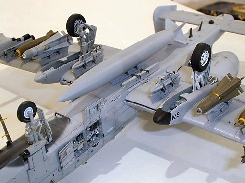
Underwing Stores
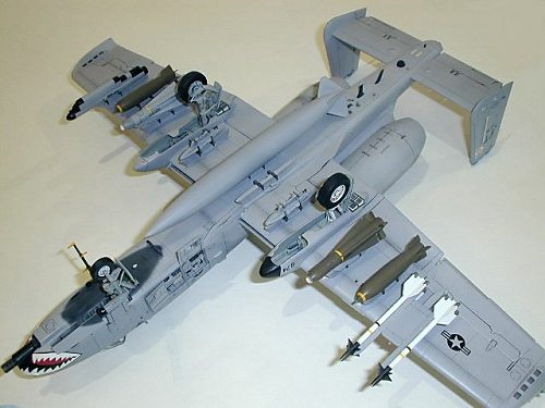 The Sidewinder dual missile rack that came with the kit is not correct for
the modern A-10s. To get it right, I scaled the dimensions provided on the ARC
walk around photos by Chris Andreychik. The dual missile rack base was made from
sheet styrene built up and sanded to the contour shown on Chris’s photos. The
rails were cut from the kit’s missile rack and glue to the new base.
The Sidewinder dual missile rack that came with the kit is not correct for
the modern A-10s. To get it right, I scaled the dimensions provided on the ARC
walk around photos by Chris Andreychik. The dual missile rack base was made from
sheet styrene built up and sanded to the contour shown on Chris’s photos. The
rails were cut from the kit’s missile rack and glue to the new base.
From reference photos, it seemed that most modern A-10s only carry the single Maverick. So a single Mav. launch rail was scratch built using one of the kit launch rail as the base and starting point. I cut strips of styrene to built up the thickness of the kit launch rail and sand it to shape. The anti-sway brace contact plates were cut from sheet styrene and glued into place.
Most reference photos show the modern A-10s carrying the AN/ALQ 184 ECM control pod. To make this version of the ECM pod, I just simply shorten the kit’s ALQ-119 ECM to scale, using reference photos as the basis for scaling. My interpretation of a World Airpower article is that during the Gulf conflict, only US based A-10s carried the long ALQ-119. However, more modern photos seem to show that most US based A-10s now carries the AN/ALQ 184 instead. Oh well, whatever.
The big external fuel tank that came with the kit looks really cool. So I decided to model the plane with this fuel tank. I checked around and have only found two photos that showed A-10s flying with this fuel tank along with other external stores on the plane.
|
PAINT & DECALS |
Pre-Painting
Just before I’m ready to paint, I take out the HUD mounting bracket and sanded it down scale thickness. Then I glue it back onto the dash and also glue on the top reinforcement plate, which I make from styrene. This reinforcement plate is shown on reference photos as a thin plate that goes on top of the HUD mounting brackets. A new HUD glass was cut from a clear styrene sheet and white glued to the mounting brackets after the painting was completed.
I rechecked all the seams by spraying a thin coat of flat Grey over most of the seams. I then washed the model using dishwashing soap and towel dried the model.
Painting
 I painted the model using Gunze 307 (FS36320) top surface and 308 (FS36375)
bottom surfaces. The false canopy on the underside of the nose was free hand
airbrushed using a mix of dark grey.
I painted the model using Gunze 307 (FS36320) top surface and 308 (FS36375)
bottom surfaces. The false canopy on the underside of the nose was free hand
airbrushed using a mix of dark grey.
The most difficult part is painting the engine intakes. My solution is 1) paint the compressor fan nose cone with 308, 2) mask the cone and paint the blades using a mix of Metalizer titanium and aluminum plate, 3) apply a liquid mask over this area, 4) paint the lip of the intake with 308 as per paint scheme, 5) remove the mask, 6) paint a clear decal sheet with an off white color, 7) lastly, develop and cut this off white colored decal and slid it into the intake.
The wheel wells were all painted Aircraft Grey. According to my reference picture, the aircraft that I modeled had a white starboard main gear strut while the port strut was color grey.
The model was given a heavy coat of Gunze gloss clear coat in preparation for decals.
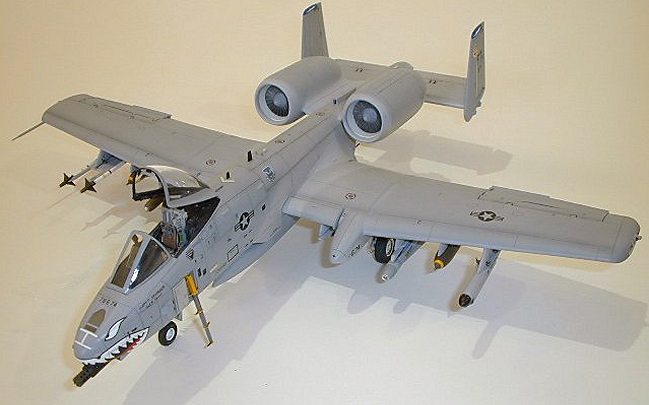
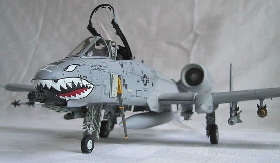
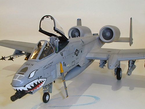
 My model depicts an A-10 from the 23rd TFW. I always loved the
A-10s with the shark mouth. The aircraft AF78-0674 was photographed by Uncle Rick
Chin last summer at Davis Monthan AFB as it was being readied for retirement to
the bone yard. To model this aircraft, I used the excellent decals from Astra
for the squadron numbers and national insignia. The Astra decal is so thin but
yet strong enough for handling. Only SuperScale produced decal for the A-10’s
shark. I manage to find this sheet on sale at Squadron and got hold of it. I
made use of the mouth and eyes and the TAC badges. The shark mouth decals do not
fit properly on the nose and leaves a ½" wide gap. I had to free hand
paint between the gap to fill in the missing teeth. The Flying Tiger badges came
from the Hasegawa A-7D kit decal sheet. Mr. Mark Softer was used to soften and
set the decals. Care must be exercised with this solution because too much
puddling on a decal will melt the decal.
My model depicts an A-10 from the 23rd TFW. I always loved the
A-10s with the shark mouth. The aircraft AF78-0674 was photographed by Uncle Rick
Chin last summer at Davis Monthan AFB as it was being readied for retirement to
the bone yard. To model this aircraft, I used the excellent decals from Astra
for the squadron numbers and national insignia. The Astra decal is so thin but
yet strong enough for handling. Only SuperScale produced decal for the A-10’s
shark. I manage to find this sheet on sale at Squadron and got hold of it. I
made use of the mouth and eyes and the TAC badges. The shark mouth decals do not
fit properly on the nose and leaves a ½" wide gap. I had to free hand
paint between the gap to fill in the missing teeth. The Flying Tiger badges came
from the Hasegawa A-7D kit decal sheet. Mr. Mark Softer was used to soften and
set the decals. Care must be exercised with this solution because too much
puddling on a decal will melt the decal.
Two errors exist with my decals. My reference photos did not clearly show the pilot’s name and the port side squadron badge on the fuselage. I would have to blame Uncle Rick for this. However, I took some liberty here at these two places and called it a day.
The whole thing was given a coat Gunze gloss clear to even out the tones. After 48 hours, a thin wash of dark grey enamel was used to accentuate panel lines. A wash of black was used to accentuate control surfaces. Then a super thin-out mixture of darkend Gunze 307 was airbrushed over certain panel lines to depict dirt as shown on some reference photographs. Finally a coat of Gunze flat was sprayed on to finish the paint job.
The main landing gears were installed after painting. To my frustration, the main gear cover plate support braces do not fit as molded. After several unsuccessful attempts, I decide to cheat and just bend the braces to fit.
|
CONCLUSIONS |
This project, from start to finish, was completed in seven months. This took much longer than I anticipated due to the shear amount of work needed to bring the model up to grade. But despite all the work, with care and attention, I ended up with a beautiful model of an ultimate tank killer and I didn’t have to wait for a new kit to come out.
June 2001
Copyright ModelingMadness.com
If you would like your product reviewed fairly and fairly quickly, pleasecontact the editor or see other details in the Note to Contributors.