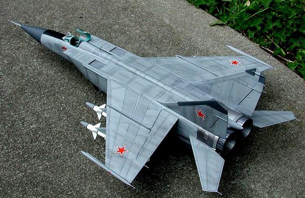
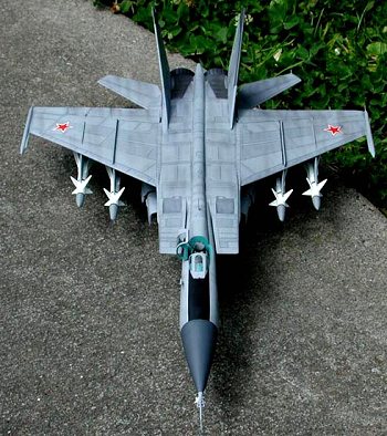
Revell 1/48 Mig-25P 'Foxbat'
|
KIT # |
|
|
PRICE: |
$10.00 |
|
DECALS: |
One aircraft |
|
REVIEWER: |
Juan Solarzano |
|
NOTES: |
|
|
THE KIT |
First of all, I want to start this construction article by saying that I didn’t know there was a 1/48 Mig-25 until about three years ago while navigating the Internet that I discovered that Revell released one back in the 70s, which wasn’t a bad but is out of production. Well, without knowing how the model looked like I wanted to have one. Thus, one day, while checking out the latest on the Hyperscale Plane Trading board I could purchase one along with a 1/48 Monogram EA-6B Prowler for ten dollars each.
One of the main reasons why I bought the kit, besides the low price, was that I have always liked the Mig-25 even though for many people this aircraft is not as good as it was thought at first. I like its shape, its story and speed.
 Few days after, I received the kit in a so
small box that I thought it wasn’t a real 1/48-scale model compared to the
Prowler box. First impressions on opening the box were mixed. The box contains
about 90 parts of medium gray plastic parts and one clear spruce containing only
a two pieces canopy. The kit has few raised panel lines, of which I would say,
90% are in wrong locations compared to reference drawings. However, when I
tried to dry fit the kit, I realized that construction could be very
straightforward. Moreover, the kit really looks like an early version Mig-25P,
which is the most important aspect to me. After some minutes of inspection, I
put the kit aside for about a year for dust collecting, waiting for some spare
time to build it.
Few days after, I received the kit in a so
small box that I thought it wasn’t a real 1/48-scale model compared to the
Prowler box. First impressions on opening the box were mixed. The box contains
about 90 parts of medium gray plastic parts and one clear spruce containing only
a two pieces canopy. The kit has few raised panel lines, of which I would say,
90% are in wrong locations compared to reference drawings. However, when I
tried to dry fit the kit, I realized that construction could be very
straightforward. Moreover, the kit really looks like an early version Mig-25P,
which is the most important aspect to me. After some minutes of inspection, I
put the kit aside for about a year for dust collecting, waiting for some spare
time to build it.
I finally had some time to start with this project and here is what happened.
I usually don’t pay attention to dimensions or extra detailing and build models straight out of the box. However, this time I wanted to build an accurate Mig-25 as possible since I believe none of the big companies as Hasegawa, Tamiya, Monogram or Academy will do a new tooling in 1/48 scale of this important aircraft in the near future.
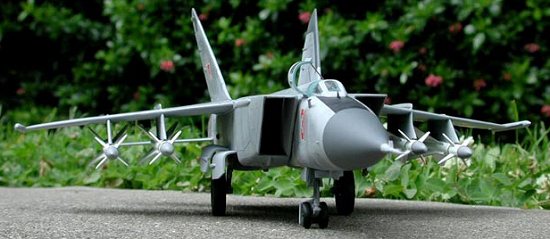
Unfortunately, I don’t have any in-process shots since I hadn't thought of posting this article on the Internet. I have some pictures of the finished model and some details that may be of use for you in your future Mig-25 project.
|
CONSTRUCTION |
Step 1
Since I wanted to do an accurate Foxbat, the first step was to check the kit dimensions against scale drawing. The drawing were scaled up to match 1/48 scale and then compared with the dimensions of the kit, which resulted to be very accurate in overall length and span, but the wings and tail planes resulted to be wider.
Step 2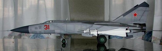
The second step was the assembly of main components. I glued the wings halves, rear fuselage halves, tail fins, radome cone, wheels, excepting the front fuselage, which couldn’t be glued yet because I didn’t have the cockpit ready yet. I glued the fuselage and wings in sections to prevent misalignment. I didn’t have any big fitting problem at all.
Step 3
The next step was to trim the wing and tail planes. Unfortunately, I don’t remember exactly the dimensions of the strip I cut to the wing exactly, but I know it was the complete leading edge slat of the kit. Regarding the tail planes, I cut about 1/8 of the front. After, I had to sand the front part of the wings and tail planes to get the leading edges to be thin as they were before, which was done with care and patience. The sanding of the tail planes was simple because they were thinner. I mostly used a steel file and Micro-Mark tadpole sanders.
When I finally got the shape that I wanted, I had to move the wings forward exactly the distance I cut to the wings. Unfortunately, moving the wings forward resulted in a nasty gap about ¼” long of the original slot that holds the wings to the fuselage on each side. I used some small pieces of styrene and Cutting Edge Modelworks Putty to fill the gap and mold the original shape. I left them dry for about half an hour and then sanded and polished them.
 Step 4
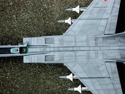
The next step was the removal of the wingtips. The kit wingtips are accurate in diameter but they are shorter and are located a little bit behind. I removed them from the kit and scratch built new ones. I used some plastic rods of one of the spruces of the kit and sanded them to get the desired shape and length and added new lights. They were glued to the wings, filled and sanded. See picture of finished wingtips.
Step 5
 The next step was the removal of raised panel
lines and scribing of new ones. This was a time consuming step because as I
stated before, the kit has few panel lines and unfortunately almost all of them
are in wrong locations. The only ones that matched the drawing I was using were
the ones on the tailfins, and again they are not 100% accurate. I removed all
raised panel lines of the kit and scribed new ones as per drawings. I used a
pencil and ruler to measure the drawings panel lines and then drew them on the
kit This step took me about two months to complete, one hour here and one hour
there. Of course, some days I didn’t do anything to the kit at all. For
removal of the raised panel lines I used 400-grit sandpaper. For scribing, I
used a Squadron scribing tool most of the time and a xacto knife in some spots
only. For curved shapes I used transparent tape as guide. For circles,
squares, oval, and other special shapes I used architectural plastic templates.
One thing that “eased” this step was that the plastic is very soft and most of
the surfaces are flat.
The next step was the removal of raised panel
lines and scribing of new ones. This was a time consuming step because as I
stated before, the kit has few panel lines and unfortunately almost all of them
are in wrong locations. The only ones that matched the drawing I was using were
the ones on the tailfins, and again they are not 100% accurate. I removed all
raised panel lines of the kit and scribed new ones as per drawings. I used a
pencil and ruler to measure the drawings panel lines and then drew them on the
kit This step took me about two months to complete, one hour here and one hour
there. Of course, some days I didn’t do anything to the kit at all. For
removal of the raised panel lines I used 400-grit sandpaper. For scribing, I
used a Squadron scribing tool most of the time and a xacto knife in some spots
only. For curved shapes I used transparent tape as guide. For circles,
squares, oval, and other special shapes I used architectural plastic templates.
One thing that “eased” this step was that the plastic is very soft and most of
the surfaces are flat.
In addition to scribing the panel lines, I
also scratch built the flaps. The flaps of the kit are too short and too wide.
Thus, I filled them with super glue in several layer until it was a bit over the
surface of the wing. I used super glue because some spots were going to be
scribed. When dry the super glue is hard as the plastic and then I can get
smooth and straight lines. After the super glue was completely dried, I
sanded it using 400-grit sandpaper. First of all, I measure the slats on
the drawings and then drew them on the kit. When the layout of the flaps was
ready, I scribed them using the Squadron scribing tool and then a sharp dentist
tool that has about the 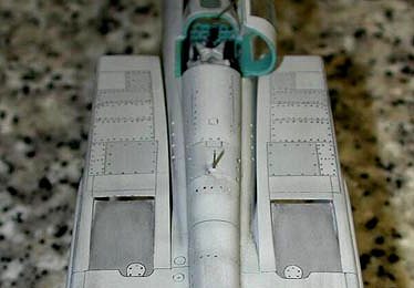 angle
I needed. Several passes were necessary as scribing has to be done little by
little and patience if you don’t want to run over the adjacent plastic. To
represent the flaps I had to do wider and deeper panel lines. When the flaps
were deep and wide enough, they were sanded using a Micro-Mark tadpole sanders.
This is a picture of the finished flaps.
angle
I needed. Several passes were necessary as scribing has to be done little by
little and patience if you don’t want to run over the adjacent plastic. To
represent the flaps I had to do wider and deeper panel lines. When the flaps
were deep and wide enough, they were sanded using a Micro-Mark tadpole sanders.
This is a picture of the finished flaps.
Step 6
Revell kit does not have spill doors or variable intakes so I decided to scratch built ones for my kit. I thought this could be eye catching. Since I had scribed the panel lines, I already knew where the spill doors would be. I used a new sharp knife to cut the plastic in order to get a sharper cutting surface and eliminate sanding and filling as possible. Once the cutting was done, I bent the plastic down just the necessary to get an opening of about 1/16. The filling and sanding was minimum. I then sanded the top of the opening to get a thin and sharp edge.
Step 7
In this step I glued the wings, tailfins and air intakes to the rear fuselage with the correct angle according to drawings. Since the wings and tailfins were glued with a different angle than the kit suggests, thin gaps appeared in the joint. To fill this gap, I applied Gunze Mr. Putty and when it was almost dry, I applied two layers of super glue on top of the putty. This allowed me to scribe a panel line that goes all the way on top of the fuselage and wings joints.
When all the pieces that complete the rear fuselage were glued, filled and sanded, all pieces were polished using 400, 600, 1500, 3200, 4000, 6000 and 8000 grit sandpapers until surface was shiny and smooth.
Step 8
The cockpit. Revell provides a very simple cockpit; it looks very bare and the basic fitting looking incorrect; a decal for the control column is also provided, which is not accurate either. Unfortunately, there is not aftermarket cockpit detail sets for the Mig-25 although there are some resin KM-1 ejection seats available.
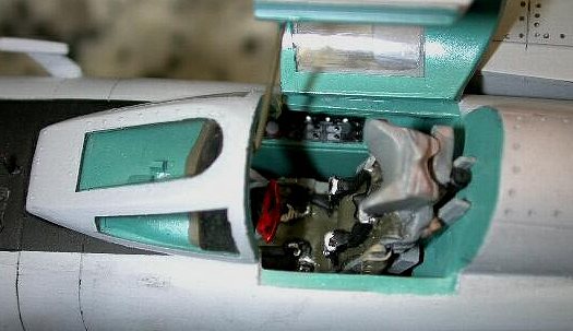 I used the tub that Revell provides, but used
Academy’s Mig-21 instruments, stick and control column that was adapted to a
Mig-25 configuration. I cut the side panel of the Academy kit and glued them on
top of the Mig-25 tub. For the sidewalls, I used Eduard Mig-21 MF photoetched
detail set. I also substituted the totally inaccurate ejection seat provided for
Revell and used a KMC KM-1 ejection seat. I also added two tiny boxes on top of
the instrument panel shroud although I’m not sure what they are in a real
aircraft.
I used the tub that Revell provides, but used
Academy’s Mig-21 instruments, stick and control column that was adapted to a
Mig-25 configuration. I cut the side panel of the Academy kit and glued them on
top of the Mig-25 tub. For the sidewalls, I used Eduard Mig-21 MF photoetched
detail set. I also substituted the totally inaccurate ejection seat provided for
Revell and used a KMC KM-1 ejection seat. I also added two tiny boxes on top of
the instrument panel shroud although I’m not sure what they are in a real
aircraft.
I painted the entire cockpit using Model Master II Russian interior green including the instrument panel shroud. In early Mig-25 Foxbats the instrument panel shrouds were painted the same color as the entire cockpit. I think this color is very green compared to pictures of Mig-25 cockpits. To get a similar color I added some drops of Testors blue to the Interior Green until I got a green-blue color similar to that seen in Mig-25 and Mig-21. I allowed the cockpit to dry a full 24 hours.
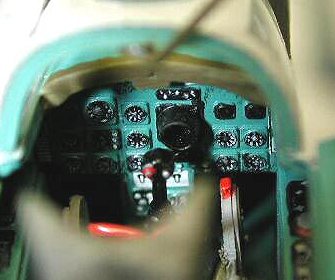 With the overall base color fully dried, I
started painting the major areas of other colors. I painted the instruments
faces, side consoles and sidewalls, the top of instrument panels hoods with
Gunze black. When the cockpit was fully dried, I applied a coat of Gunze gloss
clear to the entire cockpit and left it dry overnight. After, I drybrushed the
instrument faces again to highlight extra details. Some other spots were
drybrushed using light gray as the major wiring and tubes running around the
ejection seat. I then applied a semi-gloss clear to the entire cockpit again.
Some other details were painted red, gray and white. Finally, I applied some
weathering to the cockpit using dark gray and black pastels on the tub and
ejection seat.
With the overall base color fully dried, I
started painting the major areas of other colors. I painted the instruments
faces, side consoles and sidewalls, the top of instrument panels hoods with
Gunze black. When the cockpit was fully dried, I applied a coat of Gunze gloss
clear to the entire cockpit and left it dry overnight. After, I drybrushed the
instrument faces again to highlight extra details. Some other spots were
drybrushed using light gray as the major wiring and tubes running around the
ejection seat. I then applied a semi-gloss clear to the entire cockpit again.
Some other details were painted red, gray and white. Finally, I applied some
weathering to the cockpit using dark gray and black pastels on the tub and
ejection seat.
Although, it’s not a 100% accurate Mig-25 cockpit, it looks OK to me.
After that, the cockpit was attached to the front fuselage, which was very straightforward as well. Here are some pictures of the finished cockpit.
Step 9
Air intakes were glued to the front fuselage and the front and rear fuselages were put together and it was in this step when I had the bigger fitting problem. The joint of the two fuselages gave a step and an ugly gap. Thus, I had to decide whether to align the top and fix the bottom or the other way around. I decided to align the bottom part and fix the top, which had a flat surface. This would ease scribing of the details that would be removed by sanding. I filled up the gap using a thin plastic strip and Mr. Putty. Then, I applied few thin layers of super glue to reduce the step. After that, everything went well. Then, I sanded the super glue to remove the step starting with 320 grit wet sandpaper and then 400. I then scribed all the panel lines I had destroyed by the sanding. Finally the 4000, 6000 and 8000 grit sanding pads were used to remove all scratches.
Step 10
In this step, I scratch built the pitot tube of the radome cone. The one provided by Revell is too short and doesn’t have all the ILS antennas that a Mig-25 radome cone has. Moreover, in the real Mig-25, the pitot tube seems to be a continuation of the radome cone not a separate piece. To simulate that, I used a plastic rod and lengthened it using a small torch and glued it to the radome cone. I then applied some Mr. Surfacer 500 to the contact and sand it until I got a smooth surface and looked as one piece. Then, I cut 3/4” of a needle and glued to the end of the pitot head using white glue.
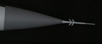 After that, I printed out the pitot head
details to scale on thick paper about the thickness of Eduard photoetched
material and cut them using a sharp blade knife. The real pitot has eight ILS
antennas instead of four provided for the kit. Again, I used white glue for it
is hard to position the antennas in the right place at first and with white glue
you always have some extra time to relocate. This is a picture of the finished
pitot tube.
After that, I printed out the pitot head
details to scale on thick paper about the thickness of Eduard photoetched
material and cut them using a sharp blade knife. The real pitot has eight ILS
antennas instead of four provided for the kit. Again, I used white glue for it
is hard to position the antennas in the right place at first and with white glue
you always have some extra time to relocate. This is a picture of the finished
pitot tube.
Step 11
In this step I attached the front canopy to the fuselage. Again the fitting was petty good. I applied Mr. Surfacer 500 to the joint to eliminate any seams and make the front canopy look as part of the fuselage as in a real aircraft.
 Step 12
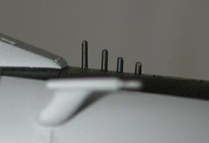
I substituted the kit antennas in front of the canopy with .5mm pencil leads. The kit contains 3 antennas, but Mig-25s have four.
Step 13
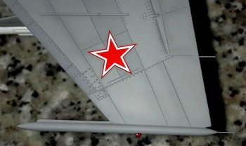
When I was about to start painting the kit, I
came up with another crazy idea. I had spent much time in the kit, why not to
spend some more.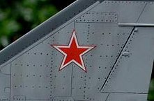 So I decided to drill all the rivets for surface detail. Since
the model was already built, there were some spots where drilling was difficult,
but with some patience and some broken bits I could drill the rivets were
needed. I didn’t use a ruler but I marked all the rivet positions with a 0.5 mm
pencil before drilling. I took me about ten hours to drill all the rivets, but
this gave the kit a better and more realistic view. This is a picture of the
tailfins for example.
So I decided to drill all the rivets for surface detail. Since
the model was already built, there were some spots where drilling was difficult,
but with some patience and some broken bits I could drill the rivets were
needed. I didn’t use a ruler but I marked all the rivet positions with a 0.5 mm
pencil before drilling. I took me about ten hours to drill all the rivets, but
this gave the kit a better and more realistic view. This is a picture of the
tailfins for example.
|
PAINT & DECALS |
Step 14
The painting. I usually don’t apply primer before painting the model, but since this project involved many sanding- scribing, sanding-scribing, I applied a layer of Floquil Railroad Primer to highlight all possible seams or scratches on the plastic. I was surprised that most of the kit looked very good after the application of the primer. Few spots had to be polished again. The flaps were sanded and polished to get a smother surface and applied a second layer of primer.
When the primer was dried I realized something, the color of the primer is a really close match to the Mig-25 color I have seen. The kit suggests a medium gray, but decided not to use it. I applied then another very thin layer and that was it for the base color.
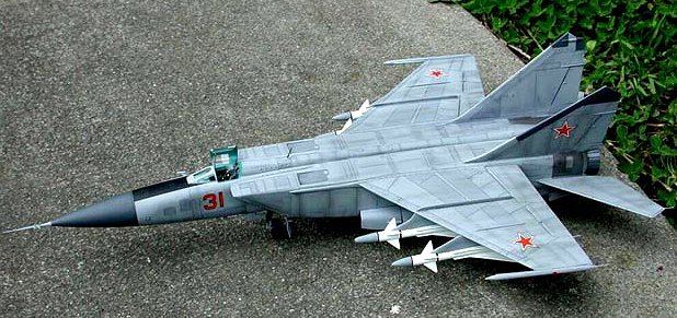
After the base color was fully dried, I mixed the base color with some drops of black to get a slightly darker color. I know that real Mig-25s are painted overall medium gray, but I have seen some artistic drawings showing different tones of gray and it seemed very nice to me. Thus, the center of the wings, some panels of the air intakes, fuselage, and leading edges were painted with a darker color to get an uneven color. Tail fins panels and radome cone were painted using Model Master Gunship Gray.
I then airbrushed all the panel lines with the same darker color very thinned.
The entire kit was then coated with Model Master gloss clear lacquer as preparation for the decals.
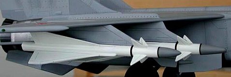 Missiles were painted with Model Master II
Semi-gloss White and tips with Dark Gull Gray. The way the missiles are layout
is really bad. I had a hard time filling, sanding and scribing. Each missile
consists of four parts, which are not many, but after these pieces are glued
together, eight ugly gaps appears per missile, so that can give you an idea the
filling and sanding involved. A good thing is that I scribed all the pieces
before they were glued. To scribe panel lines after the missiles are assembled
it would have been really a pain on the neck.
Missiles were painted with Model Master II
Semi-gloss White and tips with Dark Gull Gray. The way the missiles are layout
is really bad. I had a hard time filling, sanding and scribing. Each missile
consists of four parts, which are not many, but after these pieces are glued
together, eight ugly gaps appears per missile, so that can give you an idea the
filling and sanding involved. A good thing is that I scribed all the pieces
before they were glued. To scribe panel lines after the missiles are assembled
it would have been really a pain on the neck.
I used a drawing from a Spanish magazine called El Mundo de la Aviacion (The World of Aviation) as a reference to paint the missiles. I didn’t like the black and white colors suggested by Revell.
Step 15
The decals. Revell decals for the Mig-25 consist only of six Soviet red stars and two numbers besides the instrument panels that I didn’t use. The decals responded very well to the decal solvent. It took me about twenty minutes to decal the kit.
Step 16
Since I detailed the cockpit, I left the canopy open. Before gluing the canopy, I cut two trims of plastic to represent the ejection rails and glued them to the cockpit tub. Then I position the ejection seat.
 To represent the canopy actuator, I used a
bent pin, which was glued to middle of the front canopy. See the canopy pictures
above.
To represent the canopy actuator, I used a
bent pin, which was glued to middle of the front canopy. See the canopy pictures
above.
I also added some small pieces of thin wire to the wingtips, wing and tailplanes to simulate static dischargers.
Step 17
 Weathering. I don’t have much experience
with weathering techniques. However, I wanted to experiment. First, I applied a
wash with watercolor coil gray,
which is almost black, all over the model little by little. I applied the
watercolor paint in one small section of the model until it covered all the area
I wanted to work on until it was completely dark gray. I left it for one minute
or so until it was almost dried. After, I removed the watercolor with slightly
wet paper towel until most of it disappeared. Thus, I got two things at the
same time. I got the model to look old and dirty and highlighted the scribed
panel lines. Some spots got dirtier look than other, which gave the model a more
realistic view.
Weathering. I don’t have much experience
with weathering techniques. However, I wanted to experiment. First, I applied a
wash with watercolor coil gray,
which is almost black, all over the model little by little. I applied the
watercolor paint in one small section of the model until it covered all the area
I wanted to work on until it was completely dark gray. I left it for one minute
or so until it was almost dried. After, I removed the watercolor with slightly
wet paper towel until most of it disappeared. Thus, I got two things at the
same time. I got the model to look old and dirty and highlighted the scribed
panel lines. Some spots got dirtier look than other, which gave the model a more
realistic view.
Finally, I applied a mix of pastels over the entire model with a thick paintbrush to simulate dust.
The last step
I glued all the remaining components to the model: missiles, mainwheels, nosewheels, undercarriage wheel bays, and some antennas. Some antennas and lights were painted as final touch.
Well this project finally came to an end
|
CONCLUSIONS |
This wasn’t an easy project, but it was really fun and rewarding to me because I learned some other techniques that I can apply to future models. I didn’t count the hours I spent, but I think they were about 200-250 hours spread in four months.
I don’t think I would build another Mig-25, not because of the difficulty involved, but because the Revell Mig-25P is the only option you have. Unfortunately, to build some other versions of the Foxbat out of that model would involve even more surgery that the one required to build this early version of the Mig-25. However, I would build some other versions of the Mig-25, Mig-31, Su-24 Su-35, or Su-37 if Hasegawa, Tamiya or Academy had the guts to do a new 1/48 tooling of these monsters, but honestly, I don’t think this will happen in the next few years.
Copyright ModelingMadness.com. All rights reserved. No reproduction in part or in whole without express permission from the editor.
If you would like your product reviewed fairly and fairly quickly, please contact the editor or see other details in the Note to Contributors.