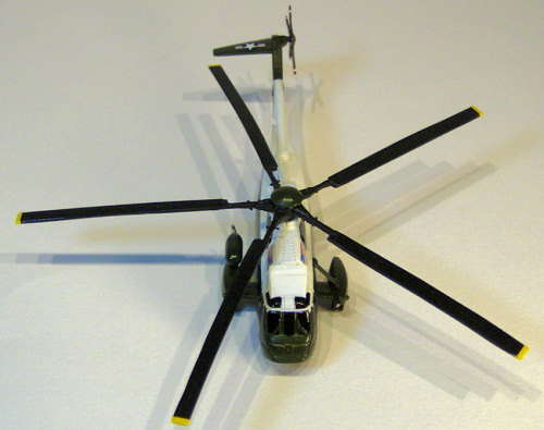
Sweet 1/144 VH-3D
| KIT #: | 14-D002 |
| PRICE: | $12.99 |
| DECALS: | Three options |
| REVIEWER: | John Kauck |
| NOTES: |
| HISTORY |
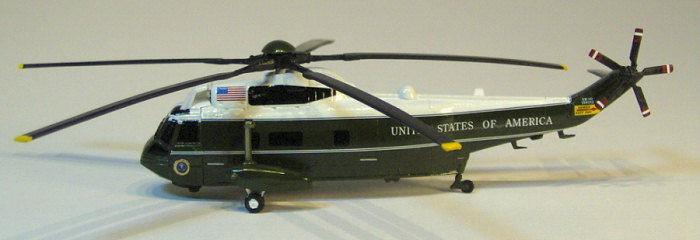
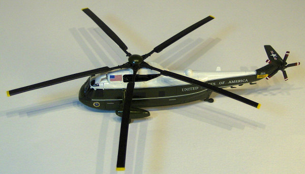
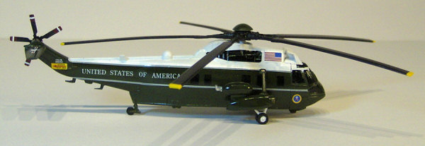
“Marine One,” VH-3D, is a twin engine, all-weather helicopter flown by Marine Helicopter Squadron One (HMX-1) and supports the executive transport mission for the President. Sikorsky delivered the VH-3D to HMX-1 in December 1974 as a replacement for the VH-3A, which entered service in 1963. By the end of 1976, the VH-3A had been completely replaced by the VH-3D.
Specifications:
Length: 73 ft (21.9 meters)
Fuselage length 54 ft, 9 in (16.5 meters)
Height: 17 ft (5.1 meters)
Engines: Two General Electric T58-GE-402 turboshaft engines
Maximum Takeoff Weight: 20,500 lbs (9,297 kg)
Maximum Range: 600 nautical miles (965 km.)
Ceiling: 14,700 ft (4,410 meters)
Speed: 140 kts (225 km/hr)
| THE KIT |
This kit from Sweet enables you to build one of three H-3 helicopter variants; the “Marine One” VH-3D Presidential Transport (which I built), a NASA SH-3G, and a Navy SH-2D, “66” of HS-4 used on the USS Hornet to recover the Apollo astronauts after splashdown. All very cool subjects.
The kit comes in a clear
plastic bag (no box) which contains all of the following: a small index size
card of instructions (really just a single diagram showing how the various
optional parts attach to each other,) a painting/decal diagram for the three
variants, a decal sheet with the decals for the three variants, two fuselage
halves, two different cockpit sections to choose from (one with a turbine intake
guard and one without), one sprue containing the main rotor blades, one sprue
containing a six-bladed tail rotor, H-3D sponsons, support struts, and a radar
dome, and yet another smaller plastic bag of parts containing a five-bladed tail
rotor, H3-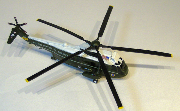 G sponsons/support
struts, the main rotor center hub, the tail wing, and the front and rear landing
gear, all loose in the bag.
G sponsons/support
struts, the main rotor center hub, the tail wing, and the front and rear landing
gear, all loose in the bag.
The “instructions” are not specific to any of the three variants. While the painting/ decal diagram provides more detail, you’ll really have to consult references of the actual specific variant you wish to build to know what parts to use for sure.
The parts are not made of typical plastic, nor are they resin, but appear to be more like vinyl. The parts are well detailed although the detail/scribing is perhaps a bit too large for scale. A retrieval hoist appears to have been a separate piece that the manufacturer apparently glued in place on the right fuselage half. (I wish they hadn’t as the VH-3D doesn’t have one.)
The decals are very good quality, i.e., thick and opaque. The presidential seal decals were for the earliest version of the VH-3D while I was building the latest version of the aircraft, (which is what I had references for) and the US flag decal is too large (for either version.) I corrected both, which I’ll cover below.
Finally, I should say that for such a small kit with relatively few parts, this kit required much more work than I initially expected in order to render an accurate representation of the subject craft, the VH-3D Marine One. Sweet would do well to create a separate third molding for this particular helicopter, at least of the fuselage, as quite a bit of sanding, correction, and scratch-building was needed to even come close to an accurate VH-3D Marine One. The following is how I did so.
| CONSTRUCTION |
Because the instruction card is not specific to any of the three variants, the first thing I did was get good reference photos for the VH-3D Marine One I wished to build. I went to the Internet and typed the designation, “VH-3D”, the nickname, “Marine One,” and “Presidential Transport” into Google Images and surfed to find around 15 good reference photos. I was careful to use consistent pictures, as this helicopter had minor changes over the years, as well as the fact that there are several in the fleet with minor differences among them. I built the most recent version currently in use as of 2006-07.
Comparing all the various parts provided in the kit to my references, I determined which parts to use to build the VH-3D. They were as follows: obviously the two fuselage halves, the cockpit section with the turbine intake guard, the smooth sponsons on the sprue, the sponson support struts also on the sprue, the radar dome, the five-bladed tail rotor, the main rotor center hub, the main rotor blades, the tail wing, and the front and rear landing gear. I set these parts aside to work on and put the rest in my spares box.
Next, I dry fit all the selected parts together to make sure they would fit together properly and to compare the semi-assembled craft to my references. The two fuselage halves and the front cockpit section fit together exceptionally well and stayed together without glue. (This is basically a snap-together kit, and therefore the fit is very good. I had to pry these 3 parts back apart with my thumbnail.) I found two minor problems. First, with the sponsons attached, the support struts didn’t line up with, nor fit into, the receiving holes for them in the fuselage. They would have to be attached flush to the surface of the fuselage. I also found that the main rotor shaft protrudes too high up out of the fuselage top. Noting these items to be addressed, I next focused more closely on each part/section individually as compared to my references.
Fuselage: The VH-3D is basically a passenger-carrying helicopter with two passenger doors on the left side (front and back), which fold down and out to become passenger stairs, and with a row of five windows on the right side (not four as indicated in the paint/decal diagram). The kit-provided fuselage is for a rescue/retrieval oriented helicopter with only the front passenger door molded in on the left side and a large sliding door molded in on the right side, with the afore mentioned retrieval hoist above the sliding door. There were also various other protruding details on the kit-provided fuselage halves while my references showed basically smooth side panels on the VH-3D.
 Therefore, I first cut off the
retrieval hoist and filled that hole as well as the misaligned sponson strut
receiving holes with thick super glue and cured these patches with accelerator.
Next, I masked the front left passenger door, the turbine intake detail, and the
detail around the top and on the spine and the rear section of the fuselage
halves. Then I sanded off the rest of the raised detail from the sides of the
cabin portions of both fuselage halves, the bottom of the fuselage, as well as
sanding down the super glue patches. Using progressively finer grit sanding
sticks, the vinyl-like plastic actually sanded down quite easily to a very
smooth surface.
Therefore, I first cut off the
retrieval hoist and filled that hole as well as the misaligned sponson strut
receiving holes with thick super glue and cured these patches with accelerator.
Next, I masked the front left passenger door, the turbine intake detail, and the
detail around the top and on the spine and the rear section of the fuselage
halves. Then I sanded off the rest of the raised detail from the sides of the
cabin portions of both fuselage halves, the bottom of the fuselage, as well as
sanding down the super glue patches. Using progressively finer grit sanding
sticks, the vinyl-like plastic actually sanded down quite easily to a very
smooth surface.
After determining the location with my dividers from my references, I then scribed the rear passenger door into the left side and touched up / re-scribed the front passenger door. I left the right side smooth, only touching up the scribed panel lines along the bottom of the cabin.
I trimmed 1/16” off the main rotor shaft (basically the squared section that inserts into the rotor hub) then re-squared the top with a medium sanding stick to fit into the rotor hub. I then dry-fit the fuselage one last time, with the shortened shaft inside, to ensure everything looked good compared to my references.
Finally, I assembled the fuselage, first super gluing the shaft support inside one fuselage half, then placing the free floating rotor shaft, then pressing the other fuselage half down onto the first. I touched the center seam in several spots with thin super glue and let capillary action draw it along the seam, careful that the shaft would still spin. I spread a little thick super glue along the spine and around the tail section to fill minor gaps, hit it with accelerator and sanded the seam smooth, careful to preserve scribed detail. I then re-scribed any sanded down lines where necessary.
Radar Dome: The kit-provided radar dome was too tall as compared to my references. Therefore, I sanded it down to size from the bottom and re-filed the channel to fit over the spine on top of the rear fuselage leading to the tail rotor. After test dry-fitting, I glued it in place with a touch of thin super glue.
Cockpit: My references showed a single pane of glass on the side windows while the kit-provided cockpit had two-piece windows on the sides. Therefore I scraped the center dividing frames off with my #11 blade. I then set it aside for painting and decaling separately.
Sponsons: My references showed smooth sided sponsons while the kit-provided sponsons had flared out sections on the bottom of the outer sides, again as they were on the earliest version. After masking the running light detail, I sanded these flares off and smoothed out the outer sides. I then glued the two sponson halves together with thin super glue for each side respectively and sanded the seams smooth on the tops and bottoms. I sanded off the alignment pin at the top and cleaned up minor flash from the sponson support struts with my #11 blade. I set the sponsons and struts, unassembled, aside for painting separately.
Landing Gear: The front landing gear came as single pieces with two wheels/tires attached to their supporting struts for each side respectively. Same for the rear, a single wheel/tire attached to its strut. These three pieces matched my references closely enough albeit with some minor flash that I cleaned up by carefully scraping with my # 11 blade. I then set them aside for painting separately.
Rotor Blades: I found the main rotor blades provided to be incorrect. They were “ribbed” while those in my references were smooth. I decided to scratch build the main rotor blades from flat styrene stock. I traced the outline of the blade portion of one of these pieces onto .050” styrene sheet. I cut out five such strips from the styrene stock with sharp scissors and as I did so the resulting strips warped slightly. Using this warp to simulate the natural sag of the rotor blades at rest, I sanded the edges into the airfoil shape on the appropriate sides (rounder/thicker on the leading edges and thinner/narrower on the trailing edges.)
I then created lap joints at the attachment points to the rotor spars. I cut the provided blades off at the second “rib” and then sanded this little two-rib section of blade down from the top to about half its original thickness. I then sanded a matching two rib long section from the bottom of the scratch built blades to half their original thickness. I then super glued the new blades to the provided blade spars overlapping the sanded section of each, then sanding these connection points smooth all around. I then attached these five corrected rotor blades to the main rotor hub with touches of thin super glue.
The 5-bladed tail rotor matched my references closely enough although they were too thick for scale. I therefore sanded each blade from both sides to make them thinner and more to scale.
Scratch built details: My references showed Auxiliary Power Plant (APP) on top of the right sponson. It’s basically an egg-shaped tank-like structure with an exhaust pipe. The kit’s paint/decal diagram shows it blacked out and no kit part is provided for it. I went through the spares box and found a 1/48 rocket that appeared to be the right circumference with guidance fins a little ways up from the tail. I cut 3 of the 4 fins away leaving the fourth to act as the supporting strut between this tank and the sponson. I then cut the rocket to the proper length on either side of this support strut/fin and rounded off the ends into an egg-shaped tank to match my references as best I could. Then I found a little 90 degree angled tube-like part to simulate what looks to be a chrome tail-pipe-like piece coming out of the rear of this “tank.” I sanded it all down to a smooth finish, cut the support fin to the proper angle and glued this thing to the right sponson with thin super glue and accelerator.
 There were also several
antennae on the helicopter in my references. I scratch built the three most
prominent of these antennae. For the fin-like antennae protruding at an angle
up from the upper right side of the rear spine section, I sanded down one of the
leftover fins from above into the proper shape and thickness. I also created
the two angled antennae under the tail section between the cabin and tail rotor
from sheet styrene stock. I attached all the antennae with touches of thin
super glue and accelerator.
There were also several
antennae on the helicopter in my references. I scratch built the three most
prominent of these antennae. For the fin-like antennae protruding at an angle
up from the upper right side of the rear spine section, I sanded down one of the
leftover fins from above into the proper shape and thickness. I also created
the two angled antennae under the tail section between the cabin and tail rotor
from sheet styrene stock. I attached all the antennae with touches of thin
super glue and accelerator.
My references also showed a dome-shaped “cap” on top of the center of the main rotor hub. Again the paint/decal diagram shows it, but the kit doesn’t provide a part for it. Going to the spares box again, I found an alternate nose for a 1/144 airliner (a Lockheed Connie, I think.) I got out my circle template and moved it over the center hub part looking for the correct diameter to cover the center hub and a little of each of the five blade spars. I settled on 7/16”. I then set this template down on top and around this nose piece, marked it, and subsequently cut the tip off with my razor saw to create the “rotor cap.” I clean it up and set it aside for painting separately.
Finally, my references also showed pointed nacelles in the center of each of the two turbine air intakes, again as does the paint/decal diagram in black, but no parts are provided in the kit. One more trip to the spares box found 1/144 jet engine nacelles (from a Boeing 707, I think.) I cut the very tips off two of these and tacked them into the center of the turbine air intakes with touches of thin super glue.
| COLORS & MARKINGS |
Note: There are black decals provided for the cabin windows but none for the cockpit windows, the cockpit piece being clear. I decided to black out the cockpit windows with black decal stock to match the cabin windows for a more consistent overall final appearance. (More on this in the Markings/Decal section below.) Given this decision, I painted over the entire cockpit piece as explained below.
I used enamels on this helicopter. First I painted the top of the fuselage and the cockpit part (separately) from the middle up over the top on both pieces with Testors #1145 Gloss White. I also painted the front landing gear parts white.
After drying 24 hours, I determined the mask line with my dividers from my references and masked off the upper white sections of the fuselage and cockpit parts horizontally and then used Model Master FS# 34097 Field Green on the lower portions of these parts, as well as the still separate sponsons, sponson support struts, tail wing, rear landing gear, and main rotor hub “cap.” Once dry, I hit all these same parts with Future to give them a gloss finish.
Next I painted the main rotor hub/blades assembly and the tail rotor blades piece with Testors #1149 Flat Black. I then masked the tail rotor blades about a third of the way down from the tips and brush painted each blade tip front and back with Testors #1104 Red. Once dry, I hit both front and tail rotor assembles with Future to give them a gloss finish in preparation for decal placement.
I also hand-painted the inside of the side exhaust ports and the tires on the landing gear with Testors #1149 Flat Black. And I hand-painted the small exhaust pipe on the APP with decanted Testors spray enamel #1290 Chrome.
Markings/Decals:
As mentioned, the kit provides a decal sheet with complete decals for all three variants that could be built. Comparing the decal sheet and the painting/decal diagram to my references, I found a few inconsistencies.
First, the presidential seals provided in the kit were incorrect for the year/version I was building. They are for the earliest version, while I was building the most recent one. They don’t have the gold rim around the outer edge with the words “President of the United States”. Luckily I had an extra decal sheet for a 1/144 C-121E, Eisenhower’s Columbine III, Minicraft kit I built and it had one correct seal on it. After numerous attempts to copy that decal to blank decal paper only to have it disintegrate (I just can’t get the hang of that technique!), I copied it onto regular paper, cut the copy out and placed it with a white glue/water mix on one side of the cockpit nose. I then placed the “borrowed” decal on the other side.
The
second inconsistency was the number and size of the windows on the right side of
the cabin. The painting/decal diagram shows four windows, again for the older
version, which is what’s provided on the decal sheet, but my references showed
five on the most recent one. Furthermore, the shapes, rectangles vs. squares,
of the various windows on this side were a little different. I just used some
of the additional rectangular windows from further down on the decal sheet and
placed all five windows on the 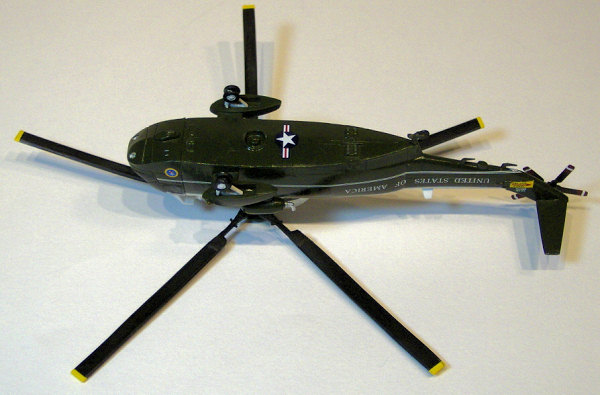 right
side according to my references. I then placed the three kit provided window
decals on the left side. Note: these window decals are connected to each other
by clear carrier film. For a better/cleaner look, I trimmed away the clear
carrier film from between them.
right
side according to my references. I then placed the three kit provided window
decals on the left side. Note: these window decals are connected to each other
by clear carrier film. For a better/cleaner look, I trimmed away the clear
carrier film from between them.
As mentioned, I blacked out the cockpit windows with black decal stock to match the cabin windows for a more consistent appearance. I used my dividers to measure inside the molded window frames and transferred this to the decal stock and cut them out with my #11 blade. I erred on the small side when cutting out and filled any gaps to the window frames with black stripe decal. I was careful to leave the windshield wipers exposed.
My references also showed a black edge around the turbine intakes, but the nacelles in white, unlike the paint/decal diagram. I cut out a tiny circle of black stock decal and placed it round the nacelles, filling in the intakes around them.
At this point, I attached the cockpit piece to the fuselage assembly with just a touch of toothpick placed super glue in the receiving holes of the fuselage and pressed the two sections together. They fit together like hand and glove! I also attached the rear wing with a tiny drop of super glue in the receiving hole.
Now I turned to the white stripe decals. I placed the upper line, starting in the rear with the 90-degree turn on the end, along the separation line between the white and green sections of the helicopter. The thicker upper line should overlap the edge of the white section. The decal is longer than needed and therefore I carefully trimmed the front end of the decal at the rear edge of the side cockpit window. I then trimmed two small segments of the leftover stripe to place on the pillars on each side of the corner cockpit window. I repeated this process on the other side of the helicopter.
Next, I placed the lower white stripes. Again the decals are longer than needed. This time I worked from front to back, mating with the flared front edge of the decal to the rear edge of the side cockpit window frame. I trimmed the leftover stripe about 1/8th inch before the rear end of the tail section. I repeated this on the opposite side. Then I removed the feathered ends of each leftover decal piece and overlapped them with the placed stripes so that the two side stripes would meet in a perfect V under the tail, behind the last antennae.
I then placed the white “US of A” lettering on each side of the rear fuselage. And I placed the yellow “Danger” decal at the bend in the tail section before the tail rotor.
I then placed the black decals around the exhausts on each side of the upper fuselage. I used plenty of the red Micro Sol “for highly irregular surfaces” to get them to nestle down into the surface detail, and while they were drying I poked the hole over the exhaust port with the blunted end of a toothpick to get the decal to conform down into the edges of the exhaust port.
Next, I placed the insignias; the larger one on the bottom of the fuselage and the smaller one on the top of the rear wing.
The last decals on the fuselage were the US flags. As I placed the first one I realized it was too large for the space when compared to my references, I immediately removed it before it was dry. I went back to the Minicraft 1/144 Columbine III decal sheet which also has the decals for the USN Blue Angels Support Connie and the tail flags for that plane on that sheet were a tad smaller then the ones provided with this kit. I used them instead.
With the body of the helicopter done, I turned to the rotors. Rather than mask and paint the tips of the main rotor, I decided to use yellow stripe decals instead. First I cut sections of stripe just long enough to cover the ends and overlap on all four sides of each blade and placed them with plenty of red Micro Sol. I then cut sections of stripe long enough to go all the way around the tips and placed them with plenty of red Micro Sol covering the edges of the previous pieces. This gives each blade a consistent look with a very clean straight line between the yellow tip and black blade.
On the tail rotor blades I cut sections of white stripe decal long enough to go all the way around the blades and placed them with plenty of red Micro Sol in the center of the previously painted red sections, leaving the look of a red, a white, then a red stripe at the end of each blade.
With all the decals in place I then covered the entire helicopter, main rotor blades and tail rotor blades with Future to “seal” the decals in. When dry, I then sprayed the main rotor blades and tail rotor blades with Testors Dullcoat from a can to give them the required flat finish.
| FINAL CONSTRUCTION |
 First, I attached the front
landing gear into the sponsons with just a tiny drop of super glue in each of
the receiving holes. I then attached the sponsons to the helicopter with just a
tiny toothpick placed drop of super glue in the receiving holes. I attached the
rear gear the same way. Then with the helicopter sitting on its wheels, and
with just a very light touch of super glue on each end, I very carefully placed
the sponson support struts between the sponson and the fuselage on each side.
First, I attached the front
landing gear into the sponsons with just a tiny drop of super glue in each of
the receiving holes. I then attached the sponsons to the helicopter with just a
tiny toothpick placed drop of super glue in the receiving holes. I attached the
rear gear the same way. Then with the helicopter sitting on its wheels, and
with just a very light touch of super glue on each end, I very carefully placed
the sponson support struts between the sponson and the fuselage on each side.
My advice: Dry-fit/practice twice! Place with glue once! You may even want to use, as I often do, a “third hand,” a small stand with a heavy iron base and one or more ball joint mounted arms with alligator-type spring clamps to hold a part in any angle required. I use them in combination with plastic hemostats (i.e., scissor clamps,) so as not to scratch the part, to position and place very small parts.
Next, I attached the tail rotor piece with a tiny drop of super glue in the receiving hole. Then I attached the scratch-built main rotor hub “cap” to the center of the main rotor hub with a tiny drop of super glue. Finally, I attached the main rotor blade assembly to the rotor shaft with a tiny drop of super glue in the receiving hole, careful that it was level and would spin freely without hitting the helicopter anywhere as it spins.
| CONCLUSIONS |
While I enjoyed the kit, as I mentioned, it was a lot more work then I expected, mainly because of all the scratch-building and corrections required to both the parts and the decals. (I want to be clear that the provided decals were correct for the oldest VH-3D version, except for the flag.)
If building one of the other variants that doesn’t require all the corrections, this kit would be a good challenge for beginners. But accurately building this variant, Marine One, as I attempted to do, would probably be a bit much for a beginner. As an intermediate modeler, I found it a challenge, but a lot of fun too. I’m sure experts would enjoy the kit as well.
| REFERENCES |
H-3 Sea King in Action, Aircraft Number 150, Squadron / Signal Publications, by Al Adcock, 1995
· Various web sites for reference photos, generated by search engine entries on the designation, callsign, and/or nickname, i.e., “VH-3D” and/or “Marine One” into Google Images and scroll through the results and you’ll get at plenty of good photos from many angles. Save the photos (right click on them and click “save photo as”) to your hard drive, then just zoom in on the area you want.
Happy Modeling!
January 2008
Copyright ModelingMadness.com. All rights reserved. No reproduction in part or in whole without express permission.
If you would like your product reviewed fairly and quickly, please contact the editor or see other details in the Note to Contributors.