| KIT #: | SH48015 |
| PRICE: | $ |
| DECALS: | Three options |
| REVIEWER: | Dave Cummings |
| NOTES: |
Short run with resin and photo etch parts |
| HISTORY |
The Spanish Civil War
(1936-39) was a pre-cursor to WWII in Europe.
Following the breakup of the Spanish monarchy a leftist
government took power in Spain.
The new government put a blind eye towards various
leftist and anarchist groups committing atrocities against former supporters of
the 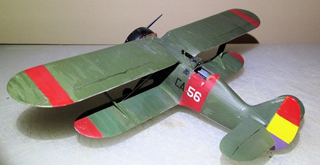 monarchy.
Property was confiscated from the wealthy, Catholic
churches were burned and priests massacred.
Many Army officers formerly loyal to the monarchy were
banished to the colonies.
One of these, General Francisco Franco, led a colonial
army in an invasion of Spain beginning a civil war.
Many foreigners supporting the socialist ideal
volunteered to fight for the government (the Republicans), forming the
International Brigade.
The Soviet Union supported the Republicans providing
weapons and a “volunteer” fighting unit.
Many Americans sympathetic to the socialist cause formed
the Lincoln Brigade, receiving much of their financing from Hollywood.
Erroll Flynn visited the Brigade at one time.
Nazi Germany and Fascist Italy likewise supported
Franco’s Fascist Nationalists.
Hitler and Mussolini also sent fighting units of
“volunteers.”
Spain became a testing ground for the latest weaponry, aircraft,
and tactics that would find use in WWII.
The Nationalists were victorious and Franco became
Dictator of Spain for the next 36 years.
Even today there are those in Spain who revere him and
those who hate his name.
monarchy.
Property was confiscated from the wealthy, Catholic
churches were burned and priests massacred.
Many Army officers formerly loyal to the monarchy were
banished to the colonies.
One of these, General Francisco Franco, led a colonial
army in an invasion of Spain beginning a civil war.
Many foreigners supporting the socialist ideal
volunteered to fight for the government (the Republicans), forming the
International Brigade.
The Soviet Union supported the Republicans providing
weapons and a “volunteer” fighting unit.
Many Americans sympathetic to the socialist cause formed
the Lincoln Brigade, receiving much of their financing from Hollywood.
Erroll Flynn visited the Brigade at one time.
Nazi Germany and Fascist Italy likewise supported
Franco’s Fascist Nationalists.
Hitler and Mussolini also sent fighting units of
“volunteers.”
Spain became a testing ground for the latest weaponry, aircraft,
and tactics that would find use in WWII.
The Nationalists were victorious and Franco became
Dictator of Spain for the next 36 years.
Even today there are those in Spain who revere him and
those who hate his name.
Among the Americans
answering the call was Frank G. Tinker (8 victories).
Tinker earned his wings as a Naval Aviator but he was a
hard drinking bar brawler in the Boyington mold to the detriment of his career.
Released by the Navy he began looking for a job as a
pilot.
He offered his services to the Spanish government and negotiated a high
salary; $1,500 a month and $1,000 for every enemy plane destroyed.
He joined the Republican Air Force in January 1937.
Flying I-15s with 1st
Esquadrilla de
 Chatos,
he shot down three enemy planes.
In May he transferred to a Russian squadron flying the
new I-16 in which he shot down five more enemy planes becoming the top scoring
American fighter pilot of the conflict.
His score included two Me-109As becoming the first pilot
to bag one of the new German fighters.
Tinker described the early 109s as about equal
to the I-16 except for an inferior rate-of-climb.
He got both of his as they attempted to climb away.
In
July 1937 Tinker resigned and returned to the US.
He wrote a series of columns about his exploits that
were later made into a book,
Some Still Live.
In these accounts he said he actually scored 19 kills.
Tinker claims a complex confirmation system was rigged
as a way for the government to avoid paying the bounty owed to mercenaries for
destroying enemy aircraft.
In 1939 Tinker signed a contract to join the Chinese Air
Force in their fight against Japan.
Before leaving however he was found dead in an
Arkansas hotel room, victim of an apparent suicide.
Little was understood about PTSD in those days.
Chatos,
he shot down three enemy planes.
In May he transferred to a Russian squadron flying the
new I-16 in which he shot down five more enemy planes becoming the top scoring
American fighter pilot of the conflict.
His score included two Me-109As becoming the first pilot
to bag one of the new German fighters.
Tinker described the early 109s as about equal
to the I-16 except for an inferior rate-of-climb.
He got both of his as they attempted to climb away.
In
July 1937 Tinker resigned and returned to the US.
He wrote a series of columns about his exploits that
were later made into a book,
Some Still Live.
In these accounts he said he actually scored 19 kills.
Tinker claims a complex confirmation system was rigged
as a way for the government to avoid paying the bounty owed to mercenaries for
destroying enemy aircraft.
In 1939 Tinker signed a contract to join the Chinese Air
Force in their fight against Japan.
Before leaving however he was found dead in an
Arkansas hotel room, victim of an apparent suicide.
Little was understood about PTSD in those days.
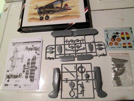
| THE KIT |
 the
cockpit details and engine.
A sheet of photo etched metal includes the instrument
panel and some other tiny bits.
An acetate instrument sheet is attached to the rear of
the metal panel with the instrument dials aligned in their holes.
This affair always produces a very realistic instrument
panel.
Some details such as engine push rods, blast tubes, and exhausts are not
provided and will have to be scratch built.
the
cockpit details and engine.
A sheet of photo etched metal includes the instrument
panel and some other tiny bits.
An acetate instrument sheet is attached to the rear of
the metal panel with the instrument dials aligned in their holes.
This affair always produces a very realistic instrument
panel.
Some details such as engine push rods, blast tubes, and exhausts are not
provided and will have to be scratch built.
Clear parts are Vac-Form.
The ten page instruction booklet is simple and shows an
exploded drawing of each assembly step.
It is clearly drawn but lacks a sequence of parts
assembly for each step.
It does include some English translations.
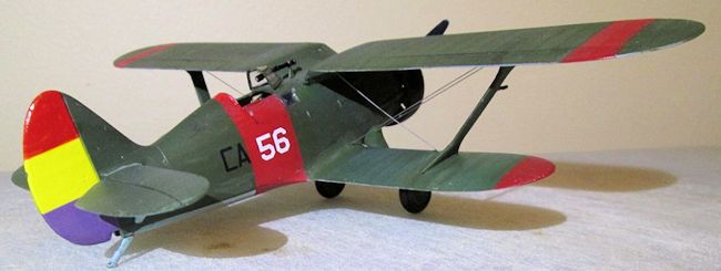
Though in black-and-white the paint schemes for three
aircraft are well depicted in 4-view.
Paint references are for Humbrol.
Decals are labeled Special Hobby and are well printed.
The red of the rudder stripes appears too orange
however. Decals
are for I-15 Black CA-142 of 1 Squadron in 1938, White 46 from 26 Group, and a
post-war Spanish AF aircraft Black 3-100.
| CONSTRUCTION |
The cockpit is comprised
of 23 resin, plastic, and PE parts.
I began by painting the resin instrument panel backing
white.
I stuck the instrument film onto the wet paint and let dry.
I superglued this to the black painted PE instrument
panel.
Looks great.
The cockpit is built as
a tub assembly.
Walls are blue-grey, seat and floor are green.
Seatbelts are
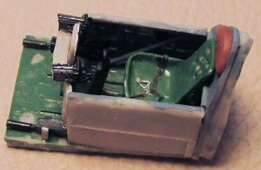 molded
to the seat.
You will need a razor saw to cut the resin parts from their
casting blocks.
They come of easily but you are dealing with some very small and
delicate parts here.
You will spend a great deal of time under the opti-visor
working at the microscopic level.
I won’t pretend this is an easy task.
But with patience a nicely detailed cockpit can be had.
At this point you must decide whether to cut out the
cockpit doors and replace them with the resin replacements in the open position.
I elected to leave mine closed to maintain the lines of the aircraft.
But this will hide most of your hard won cockpit detail.
molded
to the seat.
You will need a razor saw to cut the resin parts from their
casting blocks.
They come of easily but you are dealing with some very small and
delicate parts here.
You will spend a great deal of time under the opti-visor
working at the microscopic level.
I won’t pretend this is an easy task.
But with patience a nicely detailed cockpit can be had.
At this point you must decide whether to cut out the
cockpit doors and replace them with the resin replacements in the open position.
I elected to leave mine closed to maintain the lines of the aircraft.
But this will hide most of your hard won cockpit detail.
Next is glue the completed tub to a fuselage half. Resin cockpit tubs are notorious for being oversized. Test fitting the fuselage halves proved this one no exception. Much sanding was required to thin the walls down to fit. The instructions have you remove the tiny side windows from the vac-form sheet and attach from the inside at this point. I elected to not do it this way. I glued the fuselage halves together with tube cement for a good weld. Fit is OK but there are seams to fill. Much care is required to get the halves matched up without locating pins. Instructions show where parts go but nothing about order of assembly. I elected to attach the upper wing next. The gull wing attaches directly to the fuselage making it a solid foundation to brace the lower wings and struts against when these are butt joined in place. The wing required some sanding to fit into its slot and take care to get it square with the fuselage. Mine wanted to set up slightly canted at an angle. Some filling and sanding will be needed around this join. Next the landing gear legs glued with tube cement to strengthen the butt join. Fit was good with no seams. Then the tail planes attached. Next were the upper MG blast tubes.
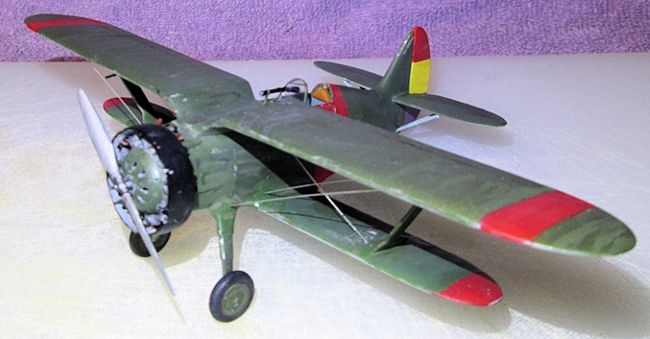
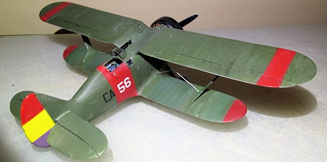
| COLORS & MARKINGS |
 At this
point I drilled all the locations for the wire rigging.
Bi-planes are best painted around this stage of
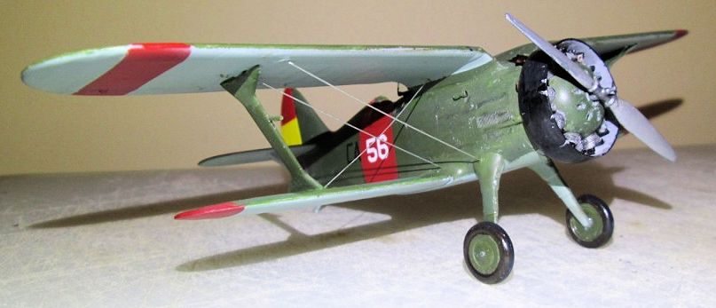
assembly. I first sprayed the red areas with Model Master Insignia Red with a
few drops of yellow to orange it up a little.
After masking I sprayed the uppers Model Master RAF Dark
Green and lowers RLM 65 Light Blue.
I lightened some dark green with white and thinned it
down.
Using a soft brush I made streaks over the green to break up the
monochrome and give it a faded under a hot Spanish sun look.
These aircraft operated under a grueling schedule from
often primitive airstrips and showed extensive operational wear and tear.
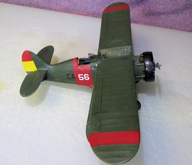
After a coat of gloss I applied the decals.
They went on well and are thin enough I didn’t need any
setting solutions.
The white 56 came from the big box of left over decals.
As stated the red of the rudder stripe decal is really
orange so I brush painted over it with my red. I then went over the forward
fuselage with a wash of thinned black acrylic to grime it up and finished with a
flat clear acrylic.
Using a toothpick I applied flat aluminum to ding up the
paint on the metal areas.
At this
point I drilled all the locations for the wire rigging.
Bi-planes are best painted around this stage of
assembly. I first sprayed the red areas with Model Master Insignia Red with a
few drops of yellow to orange it up a little.
After masking I sprayed the uppers Model Master RAF Dark
Green and lowers RLM 65 Light Blue.
I lightened some dark green with white and thinned it
down.
Using a soft brush I made streaks over the green to break up the
monochrome and give it a faded under a hot Spanish sun look.
These aircraft operated under a grueling schedule from
often primitive airstrips and showed extensive operational wear and tear.
After a coat of gloss I applied the decals.
They went on well and are thin enough I didn’t need any
setting solutions.
The white 56 came from the big box of left over decals.
As stated the red of the rudder stripe decal is really
orange so I brush painted over it with my red. I then went over the forward
fuselage with a wash of thinned black acrylic to grime it up and finished with a
flat clear acrylic.
Using a toothpick I applied flat aluminum to ding up the
paint on the metal areas.
| FINAL CONSTRUCTION |
Next is assembling the
resin engine.
This will really test your mechanics skills assembling crank
case, cylinder jugs, and separate cylinder heads and getting it all aligned
properly.
The crank case is the most beautifully detailed I have seen and
the resin cooling fins on the jugs are petite yet well defined. Unfortunately
most of these beautiful details will be hidden under the nose fairing.
The only things poking out from this are the cylinder
heads, and they don’t have any pushrods on them. So, engine winds up not so
great after all.
The engine fits into a round hole on the fuselage with a flat
area to align it properly.
The upper MG blast tubes protruding from the fuselage
slide between the cylinders and….
 Wait, nope,
they do not slide between the cylinders.
The engine won’t go on and the glue is drying, so I cut
of the protruding tubes and set the engine in place.
Were I given a re-do I would wait until now to glue on
the tubes so I could adjust them to fit the engine, not vice-versa.
The lower MG blast tubes are not provided by the kit and
the instructions show to make these from 2mm tubing. The necessity of doing so
is emphasized by the English translation, “cover
of MG barrel is engine cylinder protection against bullets.”
Not
wanting to shoot my own cylinders off, I cut some 1.5mm aluminum tubing for all
four blast tubes.
I left them in unpainted metal and I must say they look
bad-ass.
Wait, nope,
they do not slide between the cylinders.
The engine won’t go on and the glue is drying, so I cut
of the protruding tubes and set the engine in place.
Were I given a re-do I would wait until now to glue on
the tubes so I could adjust them to fit the engine, not vice-versa.
The lower MG blast tubes are not provided by the kit and
the instructions show to make these from 2mm tubing. The necessity of doing so
is emphasized by the English translation, “cover
of MG barrel is engine cylinder protection against bullets.”
Not
wanting to shoot my own cylinders off, I cut some 1.5mm aluminum tubing for all
four blast tubes.
I left them in unpainted metal and I must say they look
bad-ass.
The injection molded
cowl ring was difficult to remove from the tree.
It has several thick attachment points and is quite thin
and delicate.
It required quite a bit of sanding to clean it up and remove a
mold seam.
But amazingly, it slipped over the cylinder heads with only minor
sanding.
At this point I pondered the effort required to add some pushrods.
Since my fun-meter was about pegged already at this
point I let it slide.
I decided a more productive effort would be to open up
the cooling vents in the nose fairing.
I drilled and cut to open these up.
The fairing was then glued in place.
Again, the engine has some great detailing but it’s
mostly hidden.
What is visible are the cylinder heads that lack pushrods in
front and an exhaust system in back.
The instructions make no mention of exhausts.
I cut some stub exhaust pipes from my aluminum tubing,
painted them rust, and super glued them to the cowl ring behind each cylinder
head.
That done I glued the
wheel halves together and painted.
They look good but the holes are too small to fit the
axles.
I matched a drill bit to the axles (3/32”) and reamed out the holes,
perfect fit.
Then on to the windscreen, the vac-form sheet has two molded on
it.
This is good for forgetful old guys that place a tiny clear part down
somewhere and can’t find it again….(ahem).
Once cut from the sheet I hand painted the framing (I
tell ya, I still got it.)
Then a hole has to be drilled to accommodate the
telescopic sight.
This sight has a mount in front and a large eyepiece in
back so the hole has to be made too large for the thinner part of the tube
passing through it.
I cut the tube in half, made a hole big enough to pass
the thinner part of the tube through, and glued the tube back together.
I attached it all with fast setting super glue.
I did not use the small side windows supplied on the
sheet rather I filled the openings with clear parts cement to make these
windows. (Whoever thought up this procedure deserves a Nobel Prize).
 Next was
the fuselage to upper wing bracing wires.
I cut 10 gauge music wire and super glued to the
pre-drilled holes.
These should be double wires but I find that aligning
double wires precisely parallel detracts greatly from my fun quotient.
For those of you that worry about pushrods you may want
to do this correctly with the double wires.
Next was
the fuselage to upper wing bracing wires.
I cut 10 gauge music wire and super glued to the
pre-drilled holes.
These should be double wires but I find that aligning
double wires precisely parallel detracts greatly from my fun quotient.
For those of you that worry about pushrods you may want
to do this correctly with the double wires.
I delayed attaching the
lower wings to this point to facilitate easier handling during the build.
After scraping paint away from the strut attachment
points I used tube glue to cement the strut to the lower wing at an
approximately correct angle.
I let this set a minute until tacky then I glued the
lower wing and strut into place.
Check alignment, remember no tabs or slots.
When thoroughly dry I attached the remaining bracing
wires.
Seams around the struts and wings were filled with white glue smoothed
with a finger.
When dry I touched up the paint.
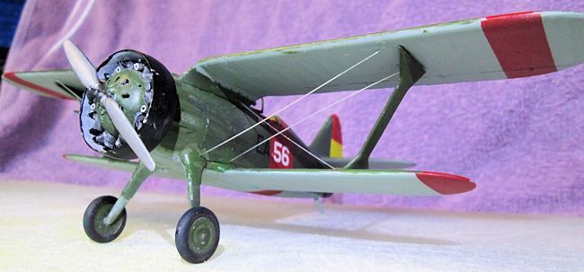
Lastly was the prop.
The blades are painted aluminum front, flat black rear,
and steel hub.
The prop shaft is way too big for the hole in the prop and would
hold the prop too far out from the engine.
Not much room to enlarge this hole so I thinned the
shaft by filing and cut it to achieve the right stand-off.
With the prop glued in place she was finished.
| CONCLUSIONS |
| REFERENCES |
Dave Cummings
November 2014
If you would like your product reviewed fairly and fairly quickly, please contact the editor or see other details in the Note to Contributors.