Glencoe 1/81 Curtiss Condor
| KIT #: | ? |
| PRICE: | $13.00 AUD |
| DECALS: | Three options |
| REVIEWER: | Alwin Broeckelmann |
| NOTES: | An old IMC kit. As a fellow reviewer has said of this kit welcome to my nightmare. |
| HISTORY |
The Condor II was a 1933 two-bay biplane of mixed construction with a single fin and rudder and retractable landing gear. It was powered by two Wright Cyclone engines. The first aircraft was flown on 30 January 1933 and a production batch of 21 aircraft were then built. The production aircraft were fitted out as 12-passenger luxury night sleeper transports. It entered service with Eastern Air Transport and American Airways, forerunners of Eastern Air Lines and American Airlines on regular night services for the next 3 years.
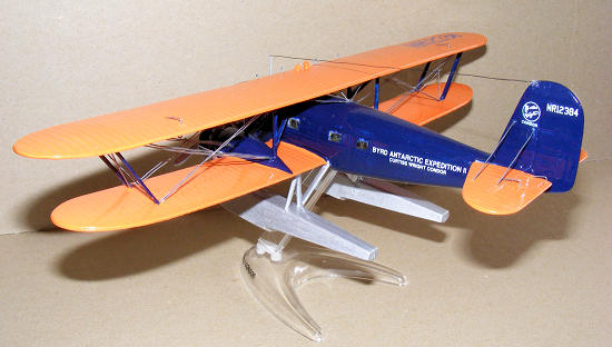
Two modified T-32s were bought by the United States Army Air Corps (designated YC-30) for use as executive transports. One Condor was converted with extra fuel tanks and used by the 1938 Byrd Antarctic Expedition, and unique for a Condor had a fixed undercarriage to allow use on floats or skis. Some aircraft were later modified to AT-32 standard with variable-pitch propellers and improved engine nacelles. The AT-32D variant could be converted from sleeper configuration to daytime use with 15 seats. Four T-32s operating in the United Kingdom were impressed into service with the Royal Air Force at the outbreak of the Second World War.
 Eight
bomber variants (BT-32) were built with manually operated machine gun turrets in
the nose and above the rear fuselage, all the aircraft were exported. A military
cargo version (CT-32) was also built with a large loading door on the starboard
side for Argentina.
Eight
bomber variants (BT-32) were built with manually operated machine gun turrets in
the nose and above the rear fuselage, all the aircraft were exported. A military
cargo version (CT-32) was also built with a large loading door on the starboard
side for Argentina.
T-32 Production luxury night sleeper, 21 built including two as YC-30s
T-32C Ten T-32s modified to AT-32 standard.
AT-32A Variant with variable-pitch propellers and 710hp (529kW) Wright SCR-1820-F3 Cyclone engines, three built.
AT-32B An AT-32 variant with 720hp (537kW) Wright SCR-1820-F2 Cyclone engines, three built.
AT-32C An AT-32 variant, one built.
AT-32D An AT-32 variant with 720hp (537kW) Wright SCR-1820-F3 Cyclone engines, one built.
AT-32E AT-32 variant for the United States Navy as the R4C-1, two built.
BT-32 Bomber variant, eight built.
CT-32 Military cargo variant with large cargo door, three built.
YC-30 United States Army Air Corps designation for two T-32s.
R4C-1 United States Navy designation for two AT-32Es (one for United States Marine Corps) both later to the United States Antarctic Survey.
| THE KIT |
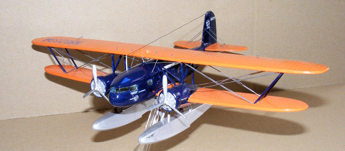
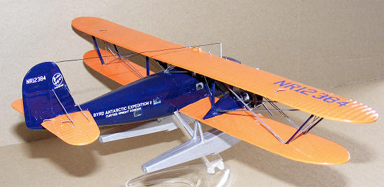
This kit is a very basic with no bulkheads or floor. There are 2 pilots and 2 passengers, which I didn’t use as the so-called transparencies or more like the bottle of a coke bottle and cannot be seen through. There are several sprues all extremely thick and brittle with a huge amount of flashing on nearly every part, the prop blades on my particular kit were misaligned in the mould and took a lot of work to get right. There is a separate sprue with all the transparencies. It can be built in 3 versions, one straight from the box as an airliner, one as an Argentinean Navy aircraft and as lastly Admiral Byrd’s 2nd Antarctic Expedition Float plane a T-32 named William Horlick, the subject of my build. The instruction were not great but adequate to follow, I did not use the sequence, as it just didn’t work for me.
| CONSTRUCTION |
 From the outset I
new I was in trouble with this one. First job was to organise all the parts into
their separate build sequences. Next task was to cut parts from sprues with a
modelers razor saw as using nippers was not an option with everything being so
brittle. There are no numbers on the sprues, so you look at the instruction
sheet to get an idea of what you are looking for. Now came the tedious task of
cleaning off all the flashing, I used a modelers scalpel, file and sand paper,
after many hours everything was to my satisfaction and I could start the actual
building.
From the outset I
new I was in trouble with this one. First job was to organise all the parts into
their separate build sequences. Next task was to cut parts from sprues with a
modelers razor saw as using nippers was not an option with everything being so
brittle. There are no numbers on the sprues, so you look at the instruction
sheet to get an idea of what you are looking for. Now came the tedious task of
cleaning off all the flashing, I used a modelers scalpel, file and sand paper,
after many hours everything was to my satisfaction and I could start the actual
building.
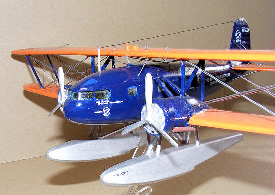
I made up the floats first, simple enough just glue together the 2 halves and leave to dry; then tidy up and paint aluminium no struts were mounted at this stage.
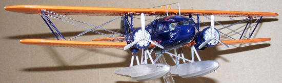
Then I started to prepare the fuselage for joining, which meant putting in all the transparencies you think. Not so fast, looking at the instruction sheet I needed to fill in windows 2,4 and 5 on the right and 2 and 4 on the left so scratch build some patches fit and glue sand now put in the remaining glass, holy cow they fall straight through as the holes or about 1mm to big. Oh well, super glue them into the bottom and forward the scratch build some fillers more sanding to tidy theses up. Glue the windscreen into the left half then bring the to fuselage halves together and hold in place with rubber/ elastic bands and allow to dry. Paint he fuselage at this point as once the top wing and rigging is in place it is impossible to get to
While that’s happening glue the top and bottom wing halves together making sure to use the correct bottoms for the bottom wing depending on your build subject. Again paint the top of the bottom wing and the bottom of the top wing. Next I fit the bottom wings to the fuselage and WOW no filling or sanding needed they fit perfectly, allow to dry then the tail plane went on using the bottom wing to get them level.
They say to put the top wing on next I didn’t but moved onto
the next delicate task of fitting the floats to the bottom wing, pre paint all
struts. Here comes another mammoth task requiring 4 pairs of hands, or super
glue. I chose the latter, using some photo’s I had sourced on the net mounted
the main struts to the floats and got the angles right by looking at the pics
and holding the float in place on the bottom wing. Now here was my dilemma, the
instructions show that they are mounted onto the bottom of the engine nacelles,
yet there are two positioning hole to the inside of each engine. These are in
fact the correct position as I found by studying photos of Byrd’s floatplane.
These are the only visible locators for the entire assembly of the floats the
rest is study 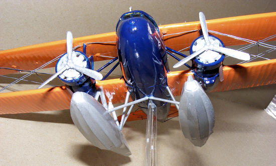 and guess work, having built many floatplanes I was not to trouble
as I know the general set-up. There are 6 mounting points on each float, then
another 5 attachment points for each one onto the fuselage. Will try to get a
couple pics to show how this was achieved, hence the need for super glue to fit
theses parts. But a word of warning, test fit, test fit, test fit then mark with
a permanent marker as once the glue is in contact with the two parts it’s there
to stay.
and guess work, having built many floatplanes I was not to trouble
as I know the general set-up. There are 6 mounting points on each float, then
another 5 attachment points for each one onto the fuselage. Will try to get a
couple pics to show how this was achieved, hence the need for super glue to fit
theses parts. But a word of warning, test fit, test fit, test fit then mark with
a permanent marker as once the glue is in contact with the two parts it’s there
to stay.
Now the engines, again much filing with a round file to get the engine surrounds to fit, as they are so thick, once fitted mount to front of nacelle. Fit exhaust to outboard side of each nacelle; leave props off till you have finished painting. We now move to fitting the top wing, first we fit the strut from the nacelles to the top of the fuselage. Next comes the tricky bit, mount the in board struts to the top of the engine nacelles and the mount the top wing into the locating holes. Here is the strange part in the instructions they lean outwards at the top, but this cannot be achieved using the locating holes they sit vertical. I left them that way and held the wings in place with a couple of coffee mugs, so they would not fall off centre. Once the glue has dried fully we fit the out board struts which are 4 separate parts, they are far too long and need trimming down to get the correct angle found in the plans and in photos. Once these are in place allow to dry for a couple of days, as they are prone to move if you haven’t let the glue fully cure. Now we paint the entire aircraft, once this is fully dry the rigging is done. I have provided a couple of links to some really good pics to assist with this as it will take 5 pages to describe the process.
| COLORS & MARKINGS |
 Painting:
There are 3 paint schemes available to the builder in the instruction sheet. An airliner, Argentinean Navy and Byrd’s William Horlick. The colour numbers are supplied in FS and Testors. Once decals have been positioned then give it a final coat of Tamiya 22 clear coat to finish off. Fit the props and all is done, time to thank the lord you have a lovely new rare bird for you collection
Decals:
The decals were a delight to work with after the nightmare build I was very tentative about using them but they work well and settled well. I always give a light coat of Tamiya 22 clear coat to the location of each decal in my builds I find this helps to get them into place properly.
| CONCLUSIONS |
This is my first Glencoe, perhaps not my last. Yes it took a great deal of work and patience. But just look at the pictures I have taken and tell me she is not a truly beautiful lady. She is a great addition to my rare bird collection and takes pride of place in the display area.
| REFERENCES |
 I have checked to
make sure all the links lead you to the correct sites, so all is good. Any
questions don’t hesitate to ask, as the only silly question is the one you never
ask as my Father always told me.
I have checked to
make sure all the links lead you to the correct sites, so all is good. Any
questions don’t hesitate to ask, as the only silly question is the one you never
ask as my Father always told me.
http://www.south-pole.com/p0000108.htm
http://en.wikipedia.org/wiki/C-30_Condor
http://www.umt.fme.vutbr.cz/~ruja/modely/podklady/Curtiss/T-32/T-32.jpg Plan view
http://www.prop-liners.com/condortech.htm
http://www.nationalmuseum.af.mil/factsheets/factsheet.asp?id=3288 Great pics for rigging. If you copy to your computer you need to lighten them up a little or I have then already done just ask for them.
March 2008
Copyright ModelingMadness.com. All rights reserved.
If you would like your product reviewed fairly and quickly, please contact the editor or see other details in the Note to Contributors.
Back to the Review Index Page 2021