
|
KIT: |
Monogram 1/48 F-8 Crusader |
|
KIT # |
5826 |
|
PRICE: |
$15.00 |
|
DECALS: |
One aircraft |
|
REVIEW & |
Wayne Hui |
|
NOTES: |
|
HISTORY |
When you think of significant Naval aircraft during the Vietnam War, several easily come to mind; F-4, A-7, A-6, A-1, and the list goes on. But, there is only one aircraft that has the reputation as a "Gun Fighter" and has a nick name of "Mig Master". The reputation and the title can only belong to the Chance Vought F-8 Crusader.
 The F-8’s served in the Vietnam war from day one until 1972.
It served in both US Navy and US Marines. It earned the nick name "MIG
Master" with 18 confirmed Mig kills to its tally. The nick name "Gun
Fighter"
The F-8’s served in the Vietnam war from day one until 1972.
It served in both US Navy and US Marines. It earned the nick name "MIG
Master" with 18 confirmed Mig kills to its tally. The nick name "Gun
Fighter"
The article and the colorful pictures of the F-8 fighters in the Osprey F-8 Crusader Units book really gave me the inspiration to do a model of the Crusader. When it comes to an F-8 in 48th scale Monogram is the only game in town. That makes it a challenge because this kit is a vintage kit and is out of production. However, my luck has it that Uncle Bills Hobby Shop just happens to have one of these vintage kit hidden in the cellar and I was able to purchase one. After buying the fantastic decals from AeroMaster, and borrowing Mike Grant’s copy of the Detail & Scale book, off I go into another S&M session with a Monogram kit. Thanks Mike.
|
THE KIT |
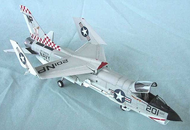
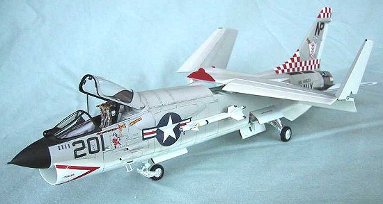
The Monogram kit is an F-8E. It can be made into a D or H version quite easily. The model I’m building is a J model flown from the USS Hancock in 1972 by the CO of VF-24 "Checkertails". The resin tail fin tip conversion for a J version is provided in the AeroMaster decal sheet No. 48-403, "Colorful Crusaders I". This is a bonus as this saved me many hours from making the conversion from scratch.
|
CONSTRUCTION |
The kit is a typical Monogram kit with raised panel lines. I rescribed all panel lines. Due to the small size and simple shape of the F-8, rescribing the panel lines is a breeze. Anyone wanting to learn how to scribe panel lines, this is the kit to practice on.
I dry fit every major parts together and found the fit to be good. If the wing is glued in the down position, there would be some gaps to be filled but, this would not matter if the model is to be shown with the wing in the raised position. Each stabilizer came in one piece and are simply pressed fitted into the hole provided in the fuselage. The highly visible air intake at the nose has a really bad seam when the fuselage halves were joined together. I used a home made putty spatula and spread a lot of putty inside the intake to fill up the seam. After more putty and sanding, I finish off the job using a thin spread of cyanoacrylate to coat the finished putty job. After the Cyano had a chance to dry, I immediately wet sand this smooth to get a seamless sucker.
The rest of the construction is very simple thus, do not require a lengthy discussion. For brevity, I will only discuss the major modification work involved with my model.
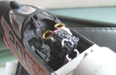
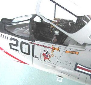
 Cockpit
I scraped away the kit raised details for the side console panels and rebuilt them using styrene sheet built-up. I made the dial buttons using thin slices of stretched spruce. The kit cockpit sides are devoid of details with the exception of the raised fuselage framing. I followed the pictures of the cockpit sides shown in Detail & Scale and made up the details using styrene.
The rear deck of the cockpit, behind the seat, have some raised ribbings used for pressure sealing the canopy to the fuselage. I added these ribbings using custom cut strips of styrene and bending them into shape. The canopy spring actuating rods were added using similar shaped rods from my scrap box.
 As of May 2001, I have read that Black Box will come out soon
with a resin cockpit set for the Monogram F-8. I guess I’m a few months too
late (or too soon in this case) to make use of it.
As of May 2001, I have read that Black Box will come out soon
with a resin cockpit set for the Monogram F-8. I guess I’m a few months too
late (or too soon in this case) to make use of it.
Modify Landing Gears
The major flaw with this Monogram kit is that the main landing gear sits too low, causing the ventral fins and the belly main gear doors to drag the ground. To correct this flaw, I followed the instructions provided in the article in the July 1992 Fine Scale Modeler and modify the landing gear length. The essence is described here.
The nose gear is length by cutting off the strut just below the gear bracing. An extension piece that is around 1/8" long was glued between the two cut off pieces to lengthen the nose gear.
The main gear takes a little more work. I first photocopy the kit’s original gear strut on a photocopier to get a template to work with. I then draw the new position of the main gear on this photocopy template. Then, I cut off the top struts near the wheel mount as shown. To get the struts down to the new position, I carefully bend both top and bottom struts until they are at the desired positions. This will result in the wheel mount being angled downward and not parallel with the horizontal. To fix this, I applied a little bit of heat to the bottom strut near the wheel mount using a match located far from the part so as not to melt it. With a bit of heat, the part became pliable and I was able to bend the wheel mount angled up a little to compensate and thus making the wheel mount close to being parallel with the horizontal.
 With
the gear in what I think is the correct position, I dry fit the wheels on and
tape the main strut part 15 into fuselage. The nose gear is also dry fit into
position at this time, with the nose wheel inserted. I made some measurements of
the ground clearance to the underside of the fuselage to confirm if I got the
gear extensions correct. I compare the actual "scaled" measurements
against the measurements given in the F-8 Detail & Scale book. If it is not
correct, I just keep bending the lower main gear strut until I got close. Once I’m
satisfied that I got it about right, I fit in a piece of extension piece made
from stretched sprue. For me this is a trial and error exercise and I’m not
too concern about getting it exactly correct. As long as it looks right, I’m
happy.
With
the gear in what I think is the correct position, I dry fit the wheels on and
tape the main strut part 15 into fuselage. The nose gear is also dry fit into
position at this time, with the nose wheel inserted. I made some measurements of
the ground clearance to the underside of the fuselage to confirm if I got the
gear extensions correct. I compare the actual "scaled" measurements
against the measurements given in the F-8 Detail & Scale book. If it is not
correct, I just keep bending the lower main gear strut until I got close. Once I’m
satisfied that I got it about right, I fit in a piece of extension piece made
from stretched sprue. For me this is a trial and error exercise and I’m not
too concern about getting it exactly correct. As long as it looks right, I’m
happy.
Alternatively, if you don’t want to go through this whole exercise and you got money to burn, you can purchase the metal correction landing gears from Cobra.
F-8E to F-8J Conversion
The Monogram F-8 kit is an F-8E or H version. The F-8Js were remanufactured F-8Es and therefore the appearance between the two versions is very similar except in a few areas. To convert it to an F-8J, I made the following modifications.
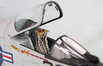
 Replace the kit seat to upgrade it to a Martin Baker Mk.F7
seat. I used a spare True Detail F-4 resin seat. I followed the pictures
shown on the Ejection Seat web site at www.bestweb.net/~kcoyne/mkf7seat.htm
to modify the F-4 resin seat. I shaved and sanded flat the head cushion
sides to resemble the metal cushion holder that is found in late Crusader
seats and painted that area black. I made the fabric pouch (seat safety pins
pouch) using leftover resin bits and painted it white and glued it to the
left side of the seat. The M.B. Mk. F7 seats has a raised seat pan sides and
had an initiator handle mounted on the right side of the seat pan side. I
made these from styrene sheets. After the seat is painted, it looks just
right.
Replace the kit seat to upgrade it to a Martin Baker Mk.F7
seat. I used a spare True Detail F-4 resin seat. I followed the pictures
shown on the Ejection Seat web site at www.bestweb.net/~kcoyne/mkf7seat.htm
to modify the F-4 resin seat. I shaved and sanded flat the head cushion
sides to resemble the metal cushion holder that is found in late Crusader
seats and painted that area black. I made the fabric pouch (seat safety pins
pouch) using leftover resin bits and painted it white and glued it to the
left side of the seat. The M.B. Mk. F7 seats has a raised seat pan sides and
had an initiator handle mounted on the right side of the seat pan side. I
made these from styrene sheets. After the seat is painted, it looks just
right.Very recently, I saw a M.B. resin seat from Cutting Edge that is for the pre-70s Phantoms and it looks just perfect as the proper replacement seat for an F-8J. All that is needed is to add the safety pin pouch.
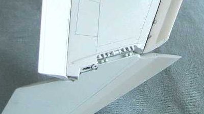
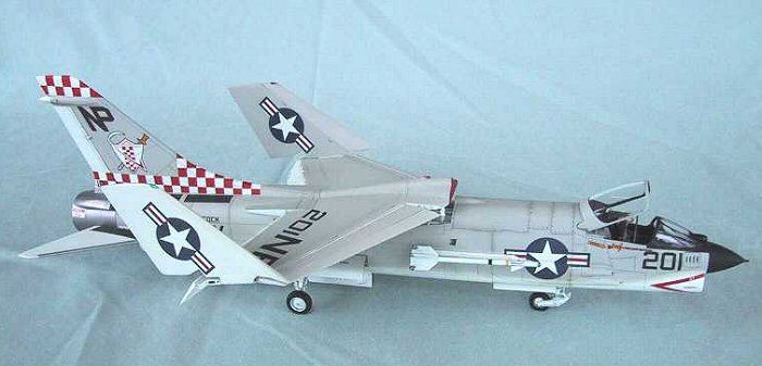
Raise the Wing
The Crusader is the only Naval aircraft I know of that has the unique raised wing feature. This feature allows a higher angle of attack during take-off and landing. The raise wing feature is only available in two position; either raised up or down. It is amazing that the raising of the wing is done by a single actuating rod near the front of the wing. The force in the rod must be tremendous during the closing of the wing when the aircraft is in flight!
The raised wing is a feature that I must represent on my F-8
model. To model the wing raised, all the flaps must be dropped and the fuselage
area under the wing must be completed. Although the Monogram kit does not
provide all the parts and  details necessary to do this, any modeler with a some basic skills
can scratch built the details to raised the wing. I followed the instruction
given in the July 1992 Fine Scale Modeler article by Donn Wells and the detail
photos in Detail & Scale to scratch build the underwing fuselage bay.
details necessary to do this, any modeler with a some basic skills
can scratch built the details to raised the wing. I followed the instruction
given in the July 1992 Fine Scale Modeler article by Donn Wells and the detail
photos in Detail & Scale to scratch build the underwing fuselage bay.
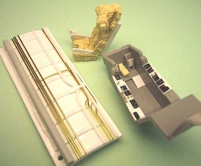
The underwing fuselage bay is scratch built using 0.03" styrene sheets cut and formed to the dimensions shown.
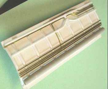 As I do not have the exact dimension for all the parts in this
bay, I had to use creative license to complete the details. To form the arch in
the bay, I placed the styrene sheet in a pot of boiling water to soften the
plastic and then quickly bend the center part over a cylindrical object until
the desired shape is formed. I used 0.060" half round styrene strips to
simulate the stiffeners. Various diameters of brass wires were used to simulate
the pipes that run from one end of the bay to the other end. The remaining
details were all made from various styrene shapes. I made two bulk heads and
glued them to the model to seal off the bay. According to the photos in Detail
& Scale and in FSM, the entire bay was painted white and was left clean. I
used two different diameter of polished aluminum tubing to make the actuating
rod; the rods were left unpainted for the natural metal look. The universal
joint detail on top of the rod was scratch built out of sheet styrene and was
painted white.
As I do not have the exact dimension for all the parts in this
bay, I had to use creative license to complete the details. To form the arch in
the bay, I placed the styrene sheet in a pot of boiling water to soften the
plastic and then quickly bend the center part over a cylindrical object until
the desired shape is formed. I used 0.060" half round styrene strips to
simulate the stiffeners. Various diameters of brass wires were used to simulate
the pipes that run from one end of the bay to the other end. The remaining
details were all made from various styrene shapes. I made two bulk heads and
glued them to the model to seal off the bay. According to the photos in Detail
& Scale and in FSM, the entire bay was painted white and was left clean. I
used two different diameter of polished aluminum tubing to make the actuating
rod; the rods were left unpainted for the natural metal look. The universal
joint detail on top of the rod was scratch built out of sheet styrene and was
painted white.
The wing should be raised such that the underside of the wing is in line with the top of the fuselage. The wing is not glued to the plane: It is held tightly in place by sandwiching the fuselage between the trailing edge flaps.
 Fold the Wing
I figured if I already raised the wing, why not fold it too. This is the easy part. Monogram kindly provided the outboard wing panels as separate pieces so you can model it folded. However, wing fold is devoid of any fold mechanical details. I added the wing locking mechanisms cut from styrene strips and bar.
Step into the Cockpit
If the canopy is open, there’s got to be a way to get into
it. To do so, there are three boarding steps that have to be added to the port
fuselage side by the cockpit. This step should be performed before the
 fuselage
is assembled.
fuselage
is assembled.
I decided to add these details in after the fuselage was already assembled. I cut out the 3 rectangular (oversized) openings on the port fuselage for the boarding steps. After I cut out the openings, I made 3 boxes from 0.01" thick styrene sheet to fit inside these cut outs to close the openings. Boarding steps were made from 0.01" sheet build-up. The bottom (lowest) step is a slide out rung and that is modeled using brass wire and styrene strip.
Detail that Large Main Gear Bay
The main landing gear bay in an F-8 is so cavernous that it begs for more details. Monogram did an excellent job of providing enough details for the attachment area surrounding the main gear, however, the front of the gear bay is devoid of detail. This is the area to concentrate the work on.
I followed the pictures in Detail and Scale and scratch built the boxes and stuff at the front of the landing gear bay. Additional piping were added using brass wires. The main fuel receptacle cover plate in the port gear bay was added and painted red. Additional "stuff" in the bay were added using similar looking model rail road parts.
Additional Add Ons
True Detail photo edge mirrors were added to the canopy frame to complete the canopy. The AIM-9Bs came from the Hasegawa weapons set.
F-8 canopy uses a spring loaded strut to pop the canopy open. To close it the pilot had to pull on a strap, which is mounted to the canopy, to get it to the close position. I model this strap using a folded aluminum paper cigarette wrapper.
|
PAINT & DECALS |
Decals
There’s not much more I need to say, the decals are AeroMaster decals. They went on great with the help of Gunze Mr. Mark Softer and Microscale Micro Sol.
Painting
Like the A-7s the F-8s had a portion of the fuselage next to the stabilizers left unpainted (bare metal). This area was subject to occasional abrasive contact from the stabilizer and if this was painted it would probably just rub off. To simulate this bare metal area, I would paint it with Model Master’s buffable aluminum color. To prepare the area where aluminum paint would go, I made a painting mask from tape and cover the area before any painting so that the metal color would go on unpainted plastic.
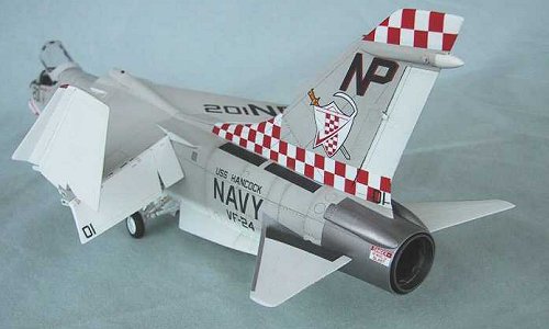 The model was painted with Gunze acrylic. The standard two
tone NAVY gull grey over white was applied using Gunze 325 (FS26440) and gloss
white. A coat of Future was applied over the model before and after application
of decals. I accentuated the panel lines with enamel dark grey and artist Raw
Sienna oil paint. The coat of Future protected the acrylic paint from the
enamel/oil panel wash. The top grey surfaces was coated with Gunze Flat to even
out the tone and a semi-gloss was sprayed on the bottom white surfaces to take
the shine off of the gloss white. Some dirty area of the panel lines were
sprayed with a mix of ultra-thinned wash of dark grey.
The model was painted with Gunze acrylic. The standard two
tone NAVY gull grey over white was applied using Gunze 325 (FS26440) and gloss
white. A coat of Future was applied over the model before and after application
of decals. I accentuated the panel lines with enamel dark grey and artist Raw
Sienna oil paint. The coat of Future protected the acrylic paint from the
enamel/oil panel wash. The top grey surfaces was coated with Gunze Flat to even
out the tone and a semi-gloss was sprayed on the bottom white surfaces to take
the shine off of the gloss white. Some dirty area of the panel lines were
sprayed with a mix of ultra-thinned wash of dark grey.
The natural metal area by the stabilizer and the rear exhaust panels were covered by a custom cut mask just before painting. After completing the painting, the masks were removed and Model Master buffable aluminum plate color was sprayed on to the bare plastic areas and buffed to a shine. The heated area of the aluminum plate by the afterburner can was painted using a mix of buffable aluminum plate and titanium.
|
CONCLUSIONS |
Without a doubt, this is the MOST GRATIFYING and MOST SATISFYING Monogram kit I have ever built. I will do another one if I can find another box, and this time I’ll use the Black Box cockpit with it.
This project only took me 3 months (on and off) to complete. Better yet, I did not have to wait for Tamiya to come out with a 1/48 scale F-8 kit. Everybody should try a hand with this kit and raise the wing. So what are you waiting for? Go find one and start enjoying this fine Monogram kit. And one more thing, shed a tear for the last gun fighter.
|
REFERENCES |
If you would like your product reviewed fairly and quickly by a site that averages over 3,000 visits a day, please contact me or see other details in the Note to Contributors.