|
KIT: |
Monogram 1/48 F-101B Voodoo |
|
KIT # |
5811 |
|
PRICE: |
$6.50 in 1985 |
|
DECALS: |
Two Aircraft |
|
REVIEW: |
Roger Jackson |
|
NOTES: |
Original Issue |
|
HISTORY |
German research into swept-wing airfoil shapes provided grist for engineers pursuing the then holy grail of sustained supersonic flight. While powerplant technology would require a few more years of gestation, extensive wind tunnel testing confirmed the earlier German hypothesis of trans-sonic theory. North American Aviation, with a new jet-powered fighter in the intermediate design stages, adopted a swept wing for their F-86, turning an also-ran into a thoroughbred.
Meanwhile, a small airplane company in St. Louis named McDonnell had designed a twin-engined swept-wing jet fighter powered by a pair of Westinghouse J-34s. Despite the fair handling characteristics of the XF-88 (the Air Force’s designation), overall performance was deemed lackluster by contemporary standards and the program was terminated.
When the supersonic wall was finally breached by North American’s F-100, NACA-supplied aerodynamic data ensured a plethora of new designs by the major players of America’s aviation industry. McDonnell, the new kid on the block with no history under its belt, carefully studied the Requests for Proposals (RFPs) issuing forth from the newly-created United States Air Force.
Strategic planners at the Pentagon, increasingly conscious of the growing Soviet threat, sought protection for the Air Force’s fleet of manned bombers, principally the B-36 and B-50. After much deliberation, requirements for a new escort fighter were drawn up and finalized. The proposed aircraft would have to be capable of long range, possess adequate firepower, and be able to compete with the best that the Soviet Air Force’s PVO-Strany (Equivalent to the USAF’s Air Defense Command) could muster.
McDonnell answered the challenge with a new twin-engined, swept-wing fighter, featuring a high-mounted stabilizer of ‘all flying design’, a razor-thin airfoil with wingroot intakes, and a powerful radar installed in the nose. Proposed armament included four 20 mm cannons, FFAR rocket packs, and Falcon air-to-air guided missiles. To extend the combat radius, both forms of aerial refueling equipment (the US-developed probe-and-drogue system and the British-owned ‘flying boom and receptacle’ method) were fitted. A pair of droptanks (360 or 450 gallon) could be carried under the fuselage. This aircraft was placed into production and designated the F-101A Voodoo.
 The powerplant selected was Pratt & Whitney’s J-57-P-13, first of the
new generation of ‘wonder engines’ and already in service, powering North
American’s Super Sabre. Featuring 10,200 lbs of military thrust with 15,000
lbs available in reheat (afterburner), the engine was more that adequate for the
task at hand. Early wrinkles, occurring during the F-100 flight test program,
had been mostly ironed out, resulting in relatively predictable performance.
The powerplant selected was Pratt & Whitney’s J-57-P-13, first of the
new generation of ‘wonder engines’ and already in service, powering North
American’s Super Sabre. Featuring 10,200 lbs of military thrust with 15,000
lbs available in reheat (afterburner), the engine was more that adequate for the
task at hand. Early wrinkles, occurring during the F-100 flight test program,
had been mostly ironed out, resulting in relatively predictable performance.
In the interim, movers and shakers in the Air Force’s Strategic Air Command (SAC) determined that propeller-driven bombers were no longer viable and that henceforth, all future designs would be turbine-powered. With less-than-optimal numbers of B-47s deployable to meet then-current commitments and the B-52 but a pipe-dream, the task fell to jet fighters currently available, including McDonnell’s F-101. The bomber escort had become the bomber!
Engineers in St. Louis hastily modified the Voodoo to carry a nuclear payload on a newly-added centerline pylon. The FFAR pods and Falcon AAM capability were deleted while the wing was re-stressed to +7.33 Gs. One cannon was removed to provide interior volume for TACAN equipment (though the weapon’s muzzle fairing remained). Reflecting the new equipment being added on an almost daily basis, midway through the production run the aircraft was redesignated the F-101C. However, concurrent developments transpiring elsewhere would assure the Voodoo a significant role in the history of the Air Defense Command.
As contingency plans for responding to diplomatic failures included nuclear strikes upon the Soviet Union and its surrogates, Pentagon planners recognized early on the need to protect the United States from similar threats from the East. Concern had mounted when Russia detonated its first atomic bomb in 1949 and rose to crisis proportions when the Soviets tested their first thermonuclear (hydrogen fusion) device shortly thereafter.
Air defense analysts were not comfortable with this new vulnerability and realized, with American cities a mere thumb-squeeze away from annihilation, that a new supersonic interceptor was desperately needed to counter this threat. Aging F-86Ds, F-89s, and F-94s had reached their maximum growth potential so a new RFP went out to the major aerospace companies.
Convair responded with a revolutionary design featuring a tailless delta-winged airframe, all-missile armament carried internally, all-weather capability with a powerful search-and-track radar, and a new Hughes-designed semi-automated fire control system. The single-seat interceptor would be powered by Pratt & Whitney’s tried-and-true J-57.
The proposal promised pie-in-the-sky performance and the Air Force, eager to provide a protective umbrella over the North American continent and under considerable political pressure to do so, ordered prototypes for production with the designation of YF-102. The pie crust soon crumbled when a myriad of problems were revealed during initial flight testing. Most serious of these were the inability of the aircraft to exceed or even attain Mach one.
Wind tunnels capable of simulating supersonic velocities had not yet been developed and the engineers at Convair had based their performance predictions on mathematical conjecture. A major re-design of the airframe would be required before the promised supersonic performance would be realized. The new MG-3 fire control system suffered teething problems as well, further delaying deployment. Hedging its bets, the Air Force stipulated that an existing supersonic aircraft be adapted to the all-weather interceptor role as a stop-gap until developmental deficiencies with the F-102 were corrected.
 The sole candidates for this mandated metamorphosis boiled down to North
American’s F-100 Super Sabre and the McDonnell F-101. The Voodoo offered a
higher top speed, a larger combat radius, and more growth potential for
additional avionics so engineers in St. Louis were tasked with modifying the
F-101 yet again to perform this new mission, beginning in May of 1955.
The sole candidates for this mandated metamorphosis boiled down to North
American’s F-100 Super Sabre and the McDonnell F-101. The Voodoo offered a
higher top speed, a larger combat radius, and more growth potential for
additional avionics so engineers in St. Louis were tasked with modifying the
F-101 yet again to perform this new mission, beginning in May of 1955.
The original APS-54 radar was replaced by the MG-13 integrated search-and-track fire control system to be operated by a weapons system operator in an added second cockpit. The cannon armament was discarded in favor of a new weapons bay featuring a rotating pallet/door assembly to which the new all-missile armament would be mounted. One side of the pallet was configured to carry two Hughes AIR-4 Falcon missiles (radar-guided ‘A’s, infrared-guided ‘C’s, or a combination) while the reverse mounted a pair of unguided nuclear-tipped Douglas MB-1 ‘Ding-Dongs’ with each warhead yielding 1.5 kilotons (low altitude deployment NOT recommended!).
Up-rated J-57-P-55 engines with 2000 lbs each of additional thrust replaced the earlier powerplants and featured beefier accessory drives to handle the larger generators dictated by the increased demand of the electrical system. The fuselage centerline hardpoint was eliminated while the droptank mounts remained unchanged. Added avionics equipment included the SAGE system (an early form of datalink telemetry) and VHF radios to allow communications with civilian aircraft and airports. For visual target identification at night or in inclement weather a powerful fixed spotlight was installed on the fuselage below the left canopy rail. Later, a new cryogenically-cooled infrared sensor would replace the retractable nose-mounted refueling probe.
The first flight of the prototype F-101B interceptor occurred in 1957 and two years later the Air Defense Command took delivery of the first production aircraft. Voodoos would eventually equip seventeen Air Force squadrons and seven Air National Guard units assigned to air defense missions.
Midway through the B’s production run, the Air Force decided it needed a pilot proficiency trainer. Accordingly, several dozen aircraft were modified during production to include dual flight controls and designated the F-101F. Full combat capability was retained and additional B models were thus modified during depot-level maintenance at Air Materiel Command Facilities. A total of 398 Bs and 72 Fs were produced.
 Canada had expressed an interest in procuring Voodoos to supplant its force
of subsonic CF-100 Canucks, pending development of its own supersonic CF-105
Arrow interceptor. In a successful effort to kill the Arrow program (thus
maintaining the primacy of the American aerospace industry), the United States
offered Canada the F-101B at near-giveaway bargain basement prices. The gamble
worked, with the Ottawa government eventually receiving 88 Voodoos (the
hoseheads!).
Canada had expressed an interest in procuring Voodoos to supplant its force
of subsonic CF-100 Canucks, pending development of its own supersonic CF-105
Arrow interceptor. In a successful effort to kill the Arrow program (thus
maintaining the primacy of the American aerospace industry), the United States
offered Canada the F-101B at near-giveaway bargain basement prices. The gamble
worked, with the Ottawa government eventually receiving 88 Voodoos (the
hoseheads!).
Canada’s aircraft were all ex-USAF machines, suitably modified and up-graded to operate continuously in extreme polar climates, and carried the designation of CF-101B, or CF-101F. The Ogden Air Materiel Center at Hill AFB in Utah performed the alterations and subsequent Time Compliance Technical Orders (TCTO) and Inspect and Repair As Necessary (IRAN) maintenance prescribed by protocol.
Interestingly enough, US F-101Bs were never deployed overseas, that honor having been bestowed upon the delta-winged darlings from Convair, the F-102 and F-106. The Voodoo would serve out its entire 24-year military career in CONUS with nary a shot fired in anger. The last American unit to fly the F-101B was the 147th TFW (Texas ANG) at Ellington AFB, with the final sortie occurring on 8 August, 1983. Canadian Voodoos remained in service until the late 1980s, when they too, were retired from service.
|
THE KIT |
Monogram’s F-101B Voodoo kit contains 97 light gray parts, a clear sprue
featuring 9, a decal sheet depicting two different schemes, and the usual
fold-out instruction pamphlet providing a short history of the aircraft,
sequential assembly steps, a coloring and decaling guide, and a paint chart
referencing specific Humbrol colors. Surface detailing consists of raised panel
lines, petitely done and, for the most part, accurate. Flaps and speedbrakes are
intended to be attached in the deployed position while the weapons bay door is
designed to rotate. Two pair of missiles are included (AIM-4 Falcons and AIR-2
Genies) along with a pair of 450 gallon droptanks.
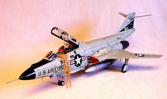
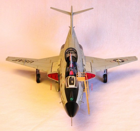
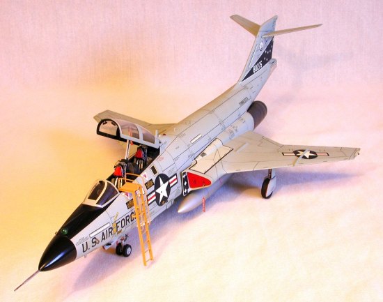
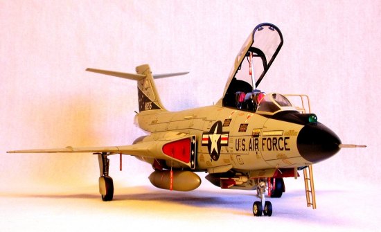
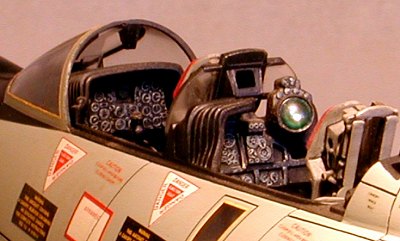
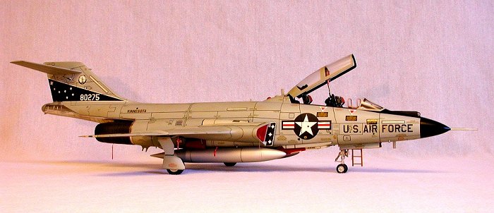
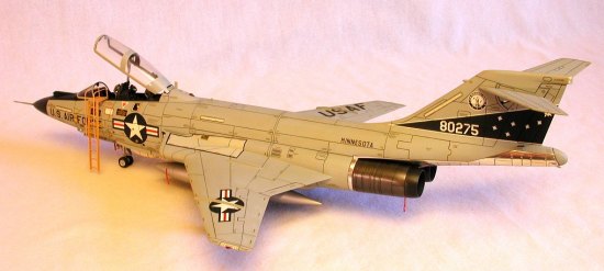
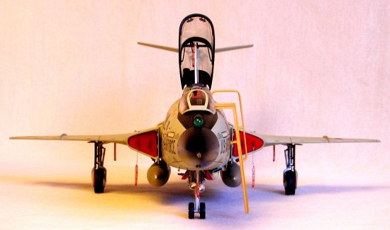
The cockpit assembly features 19 parts and is particularly well done with two seated pilot figures available for use. Clear parts include the windscreen and separate canopy, rear-view mirrors, rear cockpit blast shield, gunsight reflector glass, landing/taxi lights, and a cover for the ID spotlight. Wheels, tires, and struts are accurately shaped and modestly detailed. Full intake ducts are included with separate engine fan fronts. Most of the proper antennas are present along with separately molded afterburner cooling scoops and the primary refrigeration intake duct. A troublesome two-piece stabilator assembly rounds out the hardware. The decals are typically Monogram: on-register, slightly opaque, and totally worthless. The featured aircraft are 57-0427—a Texas ANG F-101B-100-MC from the 111th FIS, and 101027—a Canadian machine assigned to No. 409 Squadron at Comox, British Columbia.
|
CONSTRUCTION |
After attaching the inner gearwell walls to the lower wing, I glued the wing uppers to it and cleaned up the seams. A marked step between the ducts and the interior intake ramp walls convinced me that further attention in this area would be futile; the ductwork would never look realistic. Between the massive step in the ramps and the fore-shortened BLC diverters, I decided to take the coward’s way out and conceal the areas with intake covers.
Accordingly, I skipped installation of the turbine blade assemblies and added the intake backing plates. Fit and positioning was tricky, so I used small strips of tape to hold the parts in position while tacking with small drops of CA. After removing the tape, I ran a solid bead around all the mating surfaces, then dressed the areas down with a jeweler’s file and sandpaper.
 As I prefer a ‘clean’ airplane, I decided to modify the flaps so I could
install them in the ‘full up’ position. This entailed removal of the two
simulated hinge/actuators on both flaps, then carefully pre-fitting them into
their respective wells. Fit here was poor with some shimming and shaving
necessary to achieve an acceptable fit.
As I prefer a ‘clean’ airplane, I decided to modify the flaps so I could
install them in the ‘full up’ position. This entailed removal of the two
simulated hinge/actuators on both flaps, then carefully pre-fitting them into
their respective wells. Fit here was poor with some shimming and shaving
necessary to achieve an acceptable fit.
Both wingtips were notched to accept red and blue/green chunks of transparent Lexan to serve as navigation lights. After bonding with CA, I rough-shaped them via Dremel tool, then finished with file and sandpaper. When they looked about right I shined them up with a buffing wheel and jeweler’s rouge.
I rescribed the surface detail with an Xacto knife using the Verlinden photo-etched template set and a draftsman’s eraser shield as guides. Since I would be fitting droptanks to this model, I re-engineered the attachment points as described in my Wild Weasel review.
There are two droptank options for the Voodoo: 450 gallon tanks as supplied in the kit, or 360 gallon units. The larger-sized tanks limit the flight envelope to sub-sonic speeds only, while the slimmer 360 is certified for Mach 1+ IAS. There was NO way I was gonna build a supersonic interceptor and configure it as a slug, so I scratch-built a pair of 360s using the center sections from two Monogram F-4C tanks. The nose and tail assemblies were pirated from a spare set of F-84F units.
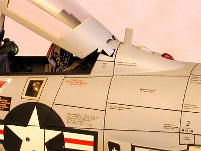
After carefully consulting my reference photos, Evergreen sheet was used to fabricate the intake covers. Straight pins, liberated from my wife’s sewing basket, were bent into ‘U’ shapes to serve as handles.
The afterburner cooling scoops needed a little TLC, so prior to installation, I drilled out the fronts and squared up the holes with a file. Massive sinkholes in the moldings required repeated fills with CA and multiple sandings to correct. When they looked like scoops, I attached them with gap-filling Hot Stuff and faired them into the lower wing with sandpaper. I cleaned up the SAGE antenna (part 96, mis-identified as a "directional antenna"), test-fitted it, then set it aside for later installation. With the wing complete, I turned next to the cockpit.
Monogram really did a commendable job here. After assembling the seats, I added a few doo-dads to the instrument panels and side consoles, including a large green MV lens to the WSO’s panel to simulate a CRT. I painted the panels black then dry-brushed flat white to bring out the details. Using my cockpit photos as reference, I picked out various bits with red, yellow, and gull gray . Seat cushions were painted with a combination of dark green (34079) and olive drab (34087), while the head and arm rests were finished in insignia red.
The basic interior color (by specification) is probably semi-gloss dark gull gray (26231), but this shade always appears too dark to me. I chose neutral gray (36270) instead since, after a dark wash, the final color would approximate the effect I was striving for. After giving all the components a wash of black Liquitex tempera watercolor, I dusted the rudder pedals, floorboards, and seat buckets with powdered graphite to grunge them up a bit, then sealed everything with Testor’s Dullcote.
 As everything completed thus far needed an assembled fuselage to attach to, I
took a look at the halves to recon for areas in need of attention. The fuel dump
vents looked pretty anemic so I fabricated new ones from slightly flattened
aluminum tubing, then beveled the ends and installed them with gap-filling Hot
Stuff.
As everything completed thus far needed an assembled fuselage to attach to, I
took a look at the halves to recon for areas in need of attention. The fuel dump
vents looked pretty anemic so I fabricated new ones from slightly flattened
aluminum tubing, then beveled the ends and installed them with gap-filling Hot
Stuff.
The engine nacelle vents needed resuscitation as well so I drilled them out, then squared and mitered the holes to accept small sections of photo-etched stainless steel grating (a model railroad item for locomotives). After tacking the corners with Crazy Glue, I ran a bead all around the grates, then sanded them flush. To avoid the see-through effect of the coincidentally-located vents, I added a baffle inside each fuselage half.
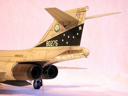
I installed a stabilator actuating cylinder constructed of a ½" length of #18 veterinary transfusion needle and a large chrome-plated pin attached to a tab on the inside of the left fin. This part would later cause a major grade-A Excedrin headache. A small NACA-style scoop on the fin’s starboard side was drilled out and relieved.
With these mods and additions complete, I painted and detailed the cockpit sidewalls, then cemented the fuselage halves together. The fit was rough as both parts were slightly warped in multiple areas. I ended up attaching some bonding strips inside, along the spine and forward of the nose gear well, to give the CA some reinforcement. When it was dry, I filed and sanded the seams flush, then added more goodies.
At the rear of the fin fairing is a transparent cover with pair of lights (white and amber) inside. To duplicate this feature, I sawed the end of the fairing off and squared up the butt end with a file. I took a chunk of clear Lucite and drilled a pair of closely-spaced holes in a flat side with a #59 bit. Weld-On #3 was used to clean up the holes and eliminate chafing and machining striations from the bit. When fully dried, I painted the insides of the holes, one amber and one white. While the paint dried I drilled a pair of holes into the rear of the fairing, with the center-to-center dimensions equivalent to the hole spacing in the Lucite. Into these holes went a couple of short pieces of stretched sprue to act as guides, insuring that my "bulbs" would line up relative to the centerline of the fairing. After a test fit, I attached the Lucite chunk to the fairing with CA, then filed and sanded the "cover" to shape. A final polishing with a buffing wheel and jeweler’s rouge restored the Lucite to transparent clarity, revealing the white and amber "bulbs" underneath.
 On the fin’s leading edge I installed the stability augmentation sensor
(Monogram missed this completely) using a bullet-shaped piece of 1/16"
aluminum tubing and a short length of #20 hypodermic needle, anchored with Crazy
Glue.
On the fin’s leading edge I installed the stability augmentation sensor
(Monogram missed this completely) using a bullet-shaped piece of 1/16"
aluminum tubing and a short length of #20 hypodermic needle, anchored with Crazy
Glue.
Like the flaps, I decided to close up the speedbrakes (I can hear the heretics howling…put a lid on it, I’m in command here). After trimming and shimming I got them to lay in their wells reasonably flush and positioned with a uniform amount of reveal around all the edges.
I rebuilt the antennas aft of the whizzo’s cockpit and added the upper anti-collision beacon, a teardrop-shaped light made from red Lexan. There was no kit-supplied lens for the ID light so, after painting the recess black, I drilled a dimple in the center of it and attached a large MV lens with white glue. The clear cover was installed with Testor’s liquid cement, sanded flush, then polished with Bare Metal compound and a piece of genuine GI T-shirt.
 The cockpit was inserted from the bottom and, after a suitable amount of
fiddling, glued in place. I test-fit the pilot’s instrument panel combing and
found that it wouldn’t lay properly due to the height of the panel . With a
router bit in my Dremel tool, I ground away the underside of the combing until
it fit properly. The kit-supplied gun sight was dumped in favor of a True
Details photo-etched brass replacement.
The cockpit was inserted from the bottom and, after a suitable amount of
fiddling, glued in place. I test-fit the pilot’s instrument panel combing and
found that it wouldn’t lay properly due to the height of the panel . With a
router bit in my Dremel tool, I ground away the underside of the combing until
it fit properly. The kit-supplied gun sight was dumped in favor of a True
Details photo-etched brass replacement.
I painted the nose wheel well pieces, then assembled and installed them in the nose. The roof of the well chafed tightly against the forward edge of the cockpit floor so, prior to actually gluing it in, I hit the top of the well with a file, thinning it sufficiently to allow for a snug but not overly-tight fit. A red anti-collision beacon was installed aft of the well.
Next, I glued the nose pieces together with CA. The depressions for the kit-supplied temperature sensor and AOA transducers were filled and sanded flush as I would be fabricating new ones from metal. I had intended to replace the IR sensor with a ball bearing, but after removing the plastic dome and tacking the ball in position, it didn’t look very convincing as an electro-optical device.
As an R & D test, I took a large diameter (4 millimeter) piece of sprue from the kit and cut one end perpendicular. A piece of bright green sheet styrene was laminated to the squared end of the sprue while a chunk of smoke gray translucent Lucite was glued to the green styrene with CA. When the "wand" was fully dry, I chucked it into my Dremel tool and rounded it down using a file, sandpaper, and low to medium speed. The hardest part of using this ‘poor man’s lathe’ was getting the hemispherical shape on the Lucite. When it was roughed in, I un-chucked the ‘wand’ and carefully hand-sanded the dome smooth using 600-grit 3M automotive film and water mixed with a little liquid dish detergent. Finally, I polished the sensor with Brasso and a buffing wheel. It had a weird dark green fluorescence to it, just the effect I was hoping for.
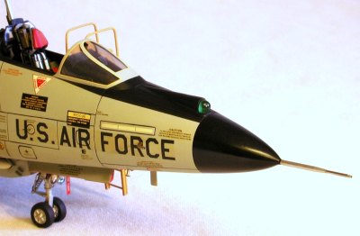 To install the sensor, I drilled out the fairing, then used my Dremel tool
with a router bit to relieve the inner walls. When the sensor ‘wand’ slid
easily into the fairing I glued it firmly from the inside with gap-filling Hot
Stuff.
To install the sensor, I drilled out the fairing, then used my Dremel tool
with a router bit to relieve the inner walls. When the sensor ‘wand’ slid
easily into the fairing I glued it firmly from the inside with gap-filling Hot
Stuff.
The plastic pitot tube was sawed off and replaced with a metal one fabricated from 1/16" aluminum tube and a #20 hypo needle. Needles, bent into a hockey stick shape, were also used for the AOA transducers, one on each side. A straight pin, with the head suitably re-shaped into a triangular configuration, was drafted to serve as the outside temperature probe. With the detailing complete, I attached the nose to the fuselage.
After sanding the seams flush, I prepared the primary refrigeration intake (part 67) for use. The front was drilled out and the lips thinned and relieved for a more in-scale appearance. It had a large molding dimple on the outside which I filled when gluing it in position. When it was satisfactorily faired in, I began rescribing the fuselage surface details.
When the panel lines had all been replaced I tackled the weapons bay. The model’s missile pallet is designed to rotate, providing a view of both types of weapons. However, no one I know had any luck at getting the thing to operate properly. I took it as a challenge to my engineering skills and vowed to make it work.
My first step was to glue the pallet pieces together. After cleaning up the seams I removed both pivot pins. I drilled a 1/16" hole into each end and inserted a correspondingly-sized piece of brass tubing all the way through both holes to act as a spindle. I cut the length a half inch longer than the pallet, letting ¼" jut out at each end. Then I removed the tubing to complete the installation.
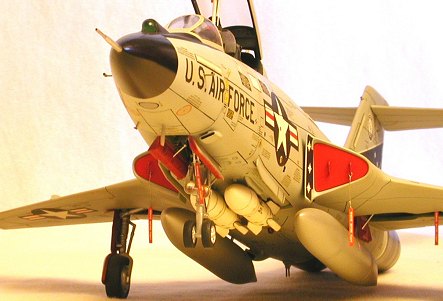 On the armament bay (part 66) I deepened the existing notches to accept
bearings made from 3/32" brass tubing. After securely gluing the bearings
in with CA, I installed the weapons bay into the fuselage. I test-fitted the
pallet by holding it in position and teasing the spindle in from the rear. With
the spindle fully seated in both bearings, I gave the pallet a turn—it worked!
On the armament bay (part 66) I deepened the existing notches to accept
bearings made from 3/32" brass tubing. After securely gluing the bearings
in with CA, I installed the weapons bay into the fuselage. I test-fitted the
pallet by holding it in position and teasing the spindle in from the rear. With
the spindle fully seated in both bearings, I gave the pallet a turn—it worked!
I prepared the missiles by assembling, painting, and decaling them, then installing brass wire pins to provide mounts for attachment. The missile pallet was removed and drilled to accept the mounting pins. Monogram omitted the sway braces for the door vane (part 25) so I added them with Evergreen .025" rod. The spoiler (part 15) looked correct and was attached after making some adjustments to its mounting tab.
The ventral strakes (parts 70 &71) provided for several hours of modeling pleasure, proving the most aggravating aspect of the weapons bay assembly. After much fiddling I achieved a passable fit, then used gap-filling CA to fair them into the fuselage. The three avionics bay exhaust ports forward of the left side of the missile pallet were drilled out to accept various diameters of aluminum tubing, installed at the proper rearward angle with Crazy Glue. When dry, I lopped off the ends and sanded them flush with the fuselage bottom. After reinstalling the missile pallet, it was time to attach the wing.
The fit here was mediocre by any standard, with multiple applications of Hot Stuff required to fill all the gaps. After a couple of evenings of filling and sanding and filling and sanding, I finally got the wing fillets to look correct and the aft fuselage properly rounded. The afterburners were assembled, rescribed, then test-fitted to the rear. A little shaving was required here to get them to sit parallel to each other.
The only remaining airframe components to be installed were the stabilators. After removing them from the sprue, I rescribed the surface detail and tried to test fit them to the fin by inserting both pieces simultaneously. The fit was extremely tight, too tight. In the service we have a sarcastic adage that goes something like ‘Don’t force it—just get a bigger hammer’. I wish I had remembered it sooner. With a loud snap, both stabilators’ mounting pins fractured and sailed off into my studio, achieving sub-orbital velocity, while the actuating cylinder dislodged itself from inside the fin and fell into the bowels of the fuselage, never to be seen again. Not exactly a Kodak moment…
 After recovering one of the mounting pins from behind a bookcase I examined
it closely. It was cratered in the exact spot that the actuator’s piston would
be if I had left it jutting out too far at the top (and apparently I had, as my
increasingly headstrong attempts to insert the stabilators’ pins had
inevitably dislodged the pesky miscreant).
After recovering one of the mounting pins from behind a bookcase I examined
it closely. It was cratered in the exact spot that the actuator’s piston would
be if I had left it jutting out too far at the top (and apparently I had, as my
increasingly headstrong attempts to insert the stabilators’ pins had
inevitably dislodged the pesky miscreant).
With the intended method of attachment ‘Tango Uniform’ (guys…help the ladies out here), I switched to Plan B, filling the mounting holes with a single piece of sprue, stuck all the way through the fin and sanded flush. I drilled a hole through the sprue plug and anchored a ½" piece of .030"steel music wire there to serve as a new attachment point for the stabilators. After bending the ends to approximate the correct sweep and dihedral, I drilled holes into the stabilators at the root and gently press-fitted them onto the rod. I purposely made the holes smaller to allow for a friction fit to the new pivot, eliminating the need for adhesive.
With the airframe complete, I test-flew it around in my studio through all flight regimes, checking the structural integrity. The specified +7.33 Gs were achieved without incident and I RTBed (returned to bench) to install the landing gear and canopy.
The main gear struts got new cast brass tie-down rings courtesy of some model railroad eye-bolts. There are no positive locators in the wells for positioning the struts so I tacked them with Testor’s liquid cement, then gently persuaded them into position. When the stance looked correct I hit them with CA to reinforce the joints. The support struts and gear link arms were tricky to position so I used Testor’s liquid here too.
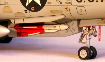 Part for part, the nose gear strut required the most additional detailing. I
cut off the drag link/steering damper assembly and built a new one with
.016" guitar string (a used one, lovingly removed from my ’59 Flame Top
Gibson Les Paul), short lengths of #25 hypo needle, and a few other pieces from
my stash box. Again, a brass tie-down ring was installed at the front. I drilled
out the clear landing/taxi lights to accept MV lenses and glued them to the
strut. Small diameter wire from Detail Associates was used as hydraulic lines.
When complete, I attached the unit to the hinge points in the gear well, then
added the support strut and uplock assembly.
Part for part, the nose gear strut required the most additional detailing. I
cut off the drag link/steering damper assembly and built a new one with
.016" guitar string (a used one, lovingly removed from my ’59 Flame Top
Gibson Les Paul), short lengths of #25 hypo needle, and a few other pieces from
my stash box. Again, a brass tie-down ring was installed at the front. I drilled
out the clear landing/taxi lights to accept MV lenses and glued them to the
strut. Small diameter wire from Detail Associates was used as hydraulic lines.
When complete, I attached the unit to the hinge points in the gear well, then
added the support strut and uplock assembly.
The struts were brush-painted with Testor’s silver then Dullcoted to give them a cast magnesium appearance. When dry, I added the MV lenses to the nose strut mounts using Microscale Liquitape. I flattened all the tires, then painted them and the wheels. When dry they were cemented to the struts with Testor’s liquid. Both main gear covers were severely dimpled, requiring multiple fills with CA. With the Hot Stuff fully cured, I sanded them smooth, painted the insides insignia red, then glued them in position.
The arresting hook was re-engineered to mount via a couple of straight pins, shortened to 5 millimeters, and glued to the front and rear of the part. I drilled a pair of holes in the keel and flexed the hook into position. The fit required no adhesive, as spring tension held the unit in place. Rearward, a small drain pipe below the drag chute door was replicated by a short piece of hypo needle installed obliquely and affixed with Crazy Glue.
Flipping the model right side up, I added the whizzo’s blast shield after first painting the metal portions black. The CRT shroud was assembled, painted, and glued in the ‘stowed’ position to the canopy bulkhead. I added a few details to the canopy actuator and dry-fitted it into the rear instrument panel recess. The windscreen was attached with Elmer’s white glue and when dry, faired to the fuselage with gap-filling Hot Stuff. After smoothing out the seam with sandpaper, I polished the glass with Bare Metal compound and a buffing wheel chucked into my Dremel tool. The kit-issued rear view mirrors looked a little lame so I replaced them with a pair of True Details photo-etched pieces, and after test-fitting the canopy a couple of times it was off to the paint shop.
|
PAINT & DECALS |
With what basically amounts to a monotone color scheme, the challenge here became an exercise in providing enough contrast between the various materials the actual aircraft was constructed of, and the overall gray finish. Accordingly, I decided to use Bare Metal foil on the unpainted rear fuselage. I’d used this technique before with moderately successful results.
Rather than attempt to cover the area with a single, large piece, I tackled the job in sections, using several small pieces, burnishing and trimming as I went. With the area fully covered, I scored the individual panels with a knife, producing the characteristic ‘sheathed’ effect of overlapping sheetmetal.
I painted the nose radome gloss black, thinned with Microscale gloss and low (20 psi) pressure. Thus applied, the radome assumed the appearance of polished dielectric fiberglass with minimal orange peel visible.
When fully dry, the nose was masked with low-tack tape, the cockpit and gearwells stuffed with Kleenex, and the exterior lights and clear windscreen panels covered with white glue. I shot the airframe with a home-brewed ADC gray, mixed years ago in the pre-Modelmaster days from Pactra enamels (remember those?), using the color chip in my FS 595a as a guide. The windscreen was undercoated with flat black to give the framing some structural definition and insure opaqueness under the gray. The canopy was similarly treated.
When the gray was dry I removed the masking, then used Testor’s lacquer thinner and a #1 sable-haired brush to remove the overspray from the bare metal areas. The SAGE antenna was attached using Testor’s liquid cement, then painted to match the airframe.
 The afterburners were painted Euro 1 gray (36081) with flat black at the ends
and inside. When dry, I burnished the exteriors with a Q-Tip dipped in powdered
graphite. This produced the pronounced ‘two-tone’ effect visible in most
Voodoo photographs. With the tailpipes complete, I cemented them in position
using small drops of gap-filling Hot Stuff.
The afterburners were painted Euro 1 gray (36081) with flat black at the ends
and inside. When dry, I burnished the exteriors with a Q-Tip dipped in powdered
graphite. This produced the pronounced ‘two-tone’ effect visible in most
Voodoo photographs. With the tailpipes complete, I cemented them in position
using small drops of gap-filling Hot Stuff.
After a week or two, I masked the anti-glare panel off and sprayed it flat black. Lacquer thinner was used again to remove the gray paint from the AOA transducers and the temperature probe. Black overspray on the pitot tube and IR sensor was likewise eliminated. With the painting complete, it was time to pick a scheme.
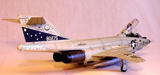
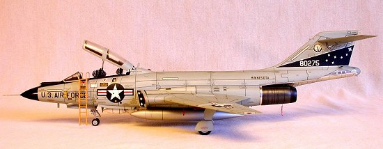
The "Texans" aircraft, attractively depicted in artfully dramatic fashion on the box top, was most appealing to me. However, the pitiful nature of Monogram’s decals precluded their use. After searching my decal database I decided to use the Experts Choice sheet (#48-25) featuring the 148th FIS, Minnesota ANG.As minimal stenciling is included, I tapped various Superscale F-4, F-100, and F-106 sheets for the myriad of servicing and warning stencils and applied them in the appropriate areas. The numerous stripes were cut from different Microscale solid color decals, while the ‘slime lights’ were from a Scalemaster sheet. The most troublesome items were the Experts Choice-provided wingwalk areas, due to the compound curves at the wing root. Painting them would have been easier but required mixing another color (36427 gray--not available commercially pre-mixed at the time I built this model). In the end, I used two sets of wingwalk decals, sectioned together and overlapped.
As the ADC gray was mixed as a gloss color, I decaled directly to it without glosscoating. To seal the decals I sprayed a light coat of semi-gloss over the gray areas. When dry, I used a thin wash of Liquitex dark gray to highlight the panel lines, control surfaces, and recessed areas in the various scoops and vents. A second coat of semi-gloss sealed the wash.
The intake covers were painted insignia red and attached with white glue. As an afterthought, I scratch-built a boarding ladder using Plastruct ‘I’ beam for the rails and Evergreen .025" rod for the rungs and grab handles. I made several ‘Remove Before Flight’ warning tags and attached them to the landing gear, arresting hook, canopy actuator, intake covers and droptank fittings with pins fabricated from light-gauge wire. After positioning the canopy onto its hinge points and actuator, I deployed the model to my display shelf.
|
CONCLUSIONS |
 Among the Century Series of aircraft, the Voodoo has always stood out as one
of my favorites. Monogram really did an admirable job of capturing the classic
lines of this majestic aircraft and, while not state-of-the-art by today’s
molding standards, a more-than-passable replica of the F-101 is possible with
this model. Today, on the verge of the re-release of the kit, there are many
aftermarket upgrades available that are sure to make detailing and assembling
this airplane that much easier. The F-101 has been well-covered by the major
decal producers, with a sizeable variety of squadron markings at the individual
modeler’s beck and call.
Among the Century Series of aircraft, the Voodoo has always stood out as one
of my favorites. Monogram really did an admirable job of capturing the classic
lines of this majestic aircraft and, while not state-of-the-art by today’s
molding standards, a more-than-passable replica of the F-101 is possible with
this model. Today, on the verge of the re-release of the kit, there are many
aftermarket upgrades available that are sure to make detailing and assembling
this airplane that much easier. The F-101 has been well-covered by the major
decal producers, with a sizeable variety of squadron markings at the individual
modeler’s beck and call.
My efforts with this kit provided me with the opportunity to explore and develop new techniques in structural engineering and replicating optical details that I’m sure I will use in future endeavors. The foiling exercise was my third attempt at using this product and , dare I say it, I was thrilled with the result--some day I may even foil an entire model. Were I to build this kit again, I’m sure I would do some things a bit different, but that’s the nature of the learning curve in this hobby.
|
REFERENCES |
1. McDonnell F-101B/F; Kevin Keaveney; Aerofax Minigraph 5
2. The F-101 Voodoo—In Detail & Scale; Bert Kinzey; Kalmbach Publishing
3. Replica In Scale; Volume 2, Number 1; Fall 1973
4. Airpower; Volume 10, Number 3; May 1980; Sentry Publishing
5. Century Series In Color; Lou Drendel; Squadron-Signal Publications
6. Voodoo; Lou Drendel & Paul Stevens; Squadron-Signal Publications
7. U.S. Fighters Of The 50s; Nico Sgarloto & Franco Ragni; Squadron-Signal Publications
8. Fighter Interceptors; Rene Francillion, Peter Lewis & Jim Dunn; Osprey Publications
9. Encyclopedia Of World Airpower; Bill Gunston; Crescent Publishing
10. Personal Observations; Pima Air & Space Museum; Tucson, Arizona
ã January 2001 Roger M. Jackson, First Time North American Rights to Fly by Nite ProductionsIf you would like your product reviewed fairly and quickly by a site that has over 1,700 visits a day, please contact me or see other details in the Note to Contributors.