|
KIT: |
Italeri 1/72 UH-1C Huey |
|
KIT # |
050 |
|
PRICE: |
$8.50 |
|
DECALS: |
See review |
|
REVIEW & |
Hans Zwetsloot |
|
NOTES: |
|
|
HISTORY |
The UH-1C, introduced in 1965, was an improved version of the UH-1B, featuring a
new rotor hub, wider chord rotor blades and a more powerful engine, the same as
installed in the larger UH-1D. These improvements provided a useful increase in
performance, as experience in Vietnam had showed the performance UH-1B to be
lacking, especially when used as a gunship. The better performance of the UH-1C
gunships allowed them to keep up with the faster troop carriers, while the
payload was increased compared to the -1B. The UH-1C and B could be armed with a
wide variety of armament systems, including M-60 machine guns, rocket pods and a
nose mounted grenade launcher turret.
The most commonly weapon systems were a pair of miniguns or seven shot rocket
pods. With the availability of the larger UH-1D the -IC was used mainly as a
gunship, eventually to be superseded by the AH-1G Cobra, although it served
until the last days of the Vietnam war.
(Editor's Note: The following information was received on 8 Jan 2001 from Kevin J. Kerle and reprinted here for your perusal.
"I have just read your review of this kit. If you
compare it to the Italeri UH-1B you will find it almost identical. The UH-1C kit
is not a UH-1C. There are several very significant differences between the B and
C. These are :
Visible Differences
1 The C has the Bell 540 semi-rigid rotor head, which is completely
different to the B.
2 The C had 27 inch blades.- the B had 21 inch
3 The C had a much wider chord cambered synchronized elevator than the B
whose was symmetrical
4 The C had a wider chord cambered tail fin than the B whose was
symmetrical.
Unseen Differences
1 The C had a much more powerful engine, hence the requirement for wider
main rotor blades, cambered synchronized elevator, and cambered tail fin
2 the C had dual hydraulic systems to increase survivability
The AH-1G was born out of the C and employed the engine, transmission, rotor,
dynamic system, and an extended cambered fin . The D played no part in the
development of the C but was a development of the B.
My references for the above is having worked around these choppers, and the Bell
Technical Data Reference on their products, as well as the relevant Technical
Manuals."
|
THE KIT |
The kit is fairly well detailed, with raised panel lines and rivet details and
it is fairly easy to build. the fuselage is split vertically, with a separate
cabin roof. The transmission/engine housing and fin are also separate parts. The
interior is completely provided with the exception of a cabin ceiling and
overhead instrument panel. It comprises a floor, seats, cyclic and collective
sticks, rudder pedals, instrument panel, a bench for the rear cabin. and two
bulkheads for the nose “bubble”. The main cabin doors are separate. The
rotor assembly comprises a mast, one piece rotor and the counterweight
crossbeam. A separate jet exhaust is provided. Two 19 shot rocket pods are
provided as ordnance.
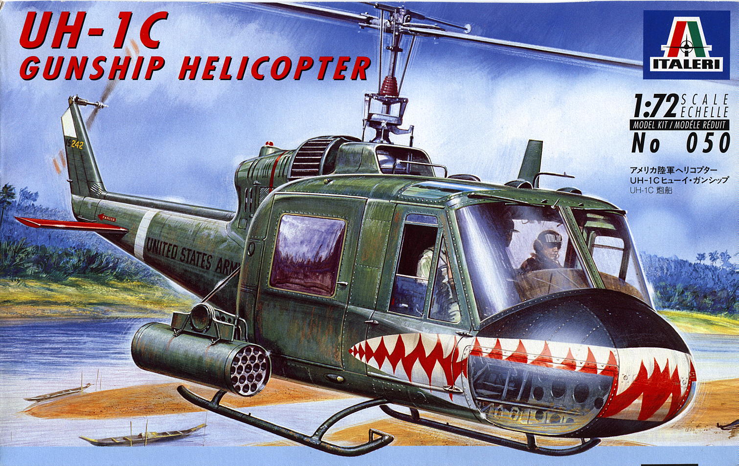
The decals sheet gives a choice between two markings, one for a US Army Huey of
the 174th AHC with colorful shark mouth markings as shown in the box-art and one
for a US Navy HA(L)-3 Huey.
The kit scales out well with the exception of the rotor. The blade chord is
about 1 mm too narrow while the diameter is16 mm too small when compared to the
dimensions given on the instruction sheet. On the kit this is not too
noticeable, though I may replace it in the future with a modified UH-1D rotor
from the spares box anyway.
|
CONSTRUCTION |
I built the kit almost straight out-of-the-box. The interior was assembled and
painted. The pilots seats include add-on body armor and molded-in seatbelts, but
lack frame details. Since the armor plates hide most of the framing anyway they
looked fine to me. The rudder pedals are a bit thick and benefit from scraping
down with sharp knife. The rear cabin bench also has molded-in seatbelts but
lacks the characteristic sag of tube & canvas seats. It is improved by
replacing the over-scale vertical posts with thinner ones, and the addition of
some bracing below the bench.
Unfortunately the missing cabin ceiling leaves some unsightly gaps. It can be
easily added by mounting a flat piece of plastic card in the separate cabin
roof. An overhead instrument panel is added together with the roof. The quilted
appearance of the cabin lining is simulated by scoring diagonal lines on the
roof panel. The gaps between the roof panel and the curved cabin roof are filled
with pieces of plastic strip as any gaps here would be visible through the roof
window panels. The interior is painted light grey, details are picked out in the
appropriate color and it is finished of with a aluminium paint dry-brush. The
transmission is assembled, painted and mounted on the rear of the rear cabin
wall. The rotor mast is left off until later. Super-detailers might want to add
the rocket sight and other small weapon related stuff in the cabin, I did not.
Fit of the whole interior assembly between the fuselage halves is tricky,
requiring scraping away some plastic here and there. I ended up with fairly
large slots for the sliding doors, a bit more patience might have yielded a
better result. Some filler was required on the bottom fuselage seam to get rid
of a noticeable step. It is advisable to add a bit of nose weight, as the kit is
a bit tail heavy. It only just balances on the rear of the skids.
After fitting of the cabin glazing the separate cabin roof is mounted. Fit is
good, providing a bit of plastic is scraped away from the underside of the cabin
roof to achieve a flush fit. I noticed this too late and was left with a small
step, which was difficult to remove. The engine housing is assembled, with the
jet exhaust edges and air intakes thinned down. Overall fit is good here.
Construction is completed by the addition of the one-piece skid, fin,
tailplanes, handles, antennas, and the one-piece skids. The “eyes” mounted
on the front of the skids are too big and were replaced. The strakes on top of
and below the fuselage were also replaced by small strips of aluminium foil,
though these kept coming of during painting as there is hardly any contact
surface for the (cyano)glue. Any ideas here on how to mount such thin parts? The
rotor and rocket pods were left off until painting is completed.
|
PAINT & DECALS |
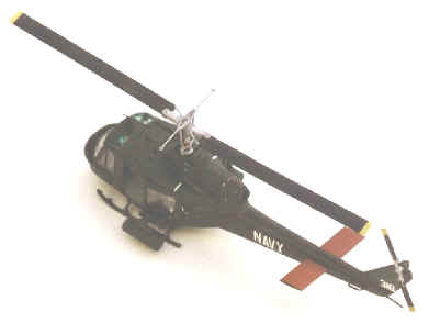
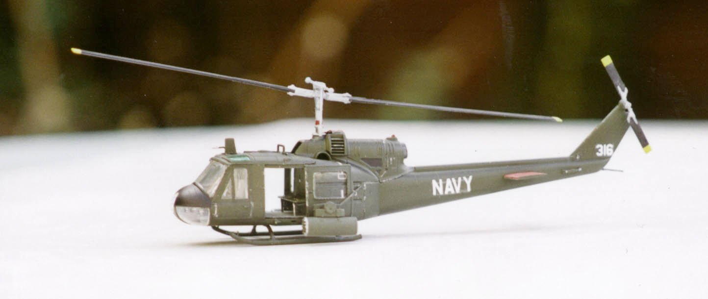
I chose to use the HA(L)-3 color scheme which is very simple, being olive drab
overall, with a flat black anti glare panel and red tailplane upper surfaces.
The rotor blades are black with yellow tips. The kit is sprayed with gloss paint
for application of the decals, which are then covered by a final flat coat. The
overhead window panels were painted with clear green paint.
|
FINISHING |
After painting the main and tail rotor are assembled and painted. The look of
the model is improved by mounting the rotor with one blade down, as seen on many
photographs of Hueys. The rocket pods are assembled, painted and mounted. Fit of
the mounting brackets is not good, the pods almost touching the ground when
mounted in the appropriate slots. Using photos from references as a guidance the
mountings are scraped off and repositioned until a better sit is achieved.
Finally the main doors are mounted in the open position, although they might be
left off as well, since this was frequently done to save weight.
|
CONCLUSIONS |
Although there are a few fit and rotor size problems and some areas that need
some extra detailing this is a pleasant kit to build, making up a nice looking
model of the Huey.
|
REFERENCES |
Vietnam, the helicopter war (Philip D. Chinnery, Airlife Publications)
Various photo’s downloaded from the Internet
If you would like your product reviewed fairly and quickly by a site that has over 900 visits a day, please contact me or see other details in the Note to Contributors.