| KIT #: | 72-024 |
| PRICE: | €32,50 |
| DECALS: | One option |
| REVIEWER: | Jeroen Koen |
| NOTES: | Reboxed Roden kit with resin, p.e. and new decals |
| HISTORY |
The Machine
During WWI, the Austro-Hungarian Empire sought to improve the quality of the
fighter aircraft equipping its Luftfahrttruppen units by producing a licensed
build version of Germany's highly successful Albatros D.III. In the process, the
Österreichische Flugzeugfabrik A.G. (Öffag or Oeffag) plant in Wiener-Neustadt,
evolved a noticeably different cousin to it's German predecessor. The third
production series, S.253, represented the pinnacle of this offshoot airframe
-these machines were fit with a 225hp Austro-Daimler engine, neatly faired
within distinctive round noses (giving improvements in speed and propeller
efficiency). Further, the Öffag engineers reworked the single lower wing spar
installation and succeeded in eliminating the wing failures that had haunted the
original German D.III “V-strut” sesquiplanes.
(according to Paolo Verriale in “Cross and Cockade, they were reduced,
but not entirely eliminated -JK)
Other typical characteristics of the S.253 machines were internally mounted
machine guns, individual exhaust stacks for each cylinder, ailerons en elevator
with wire trailing edges (which gave a scalloped appearance by taught linen
skin) and a raked tailskid support. Following the end of the war, Öffag supplied
30 S.253s for sale to the newly constituted nation of Poland for service in the
nascent Polish Air Force. These aircraft were used extensively in the border
disputes that Poland
 found itself embroiled in before the ink on the Versailles
Treaty was dry -the war to end al wars, sadly, did not. Polish S.253s were most
famously employed during the Polish-Soviet war of 1919-1921.
found itself embroiled in before the ink on the Versailles
Treaty was dry -the war to end al wars, sadly, did not. Polish S.253s were most
famously employed during the Polish-Soviet war of 1919-1921.
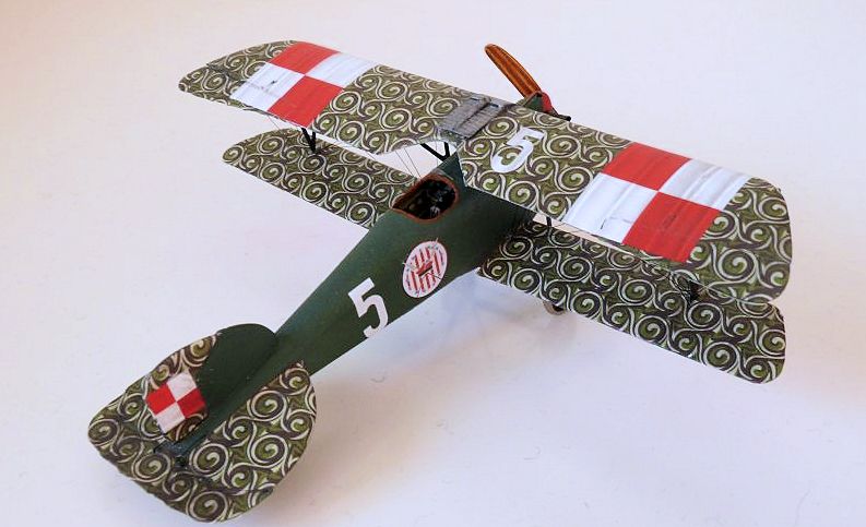
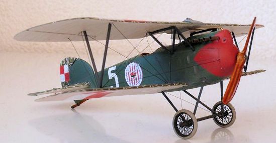
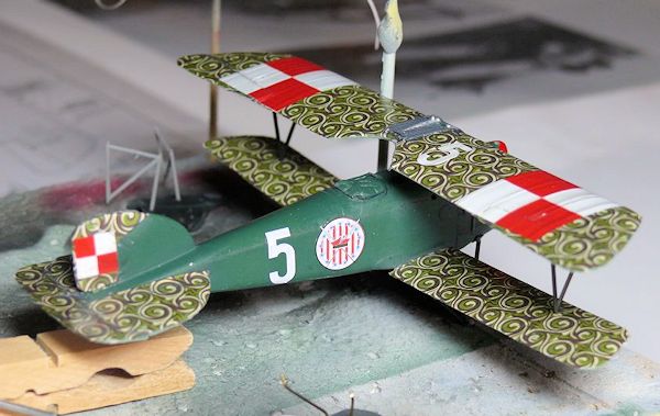
Albatros D.III Öffag serial number 253.218, marked White 5 was assigned to
Kapitan Merian C. Cooper, CO of Pulaski Flight of the 7th Escadra
Mysliwska “Kósciuszko” during the late winter of 1919 – spring of 1920. White 5
was recorded destroyed on 7th June, 1920, when it was burned by
ground personnel as part of the retreat from Berdyczów in present day Ukraine.
The Insignia
The Kósciuszko unit badge, still in use today by the Polish Air Force, was
designed by American pilot Lt. Elliott Chess. While the stars and stripes recall
the American Revolution of 1775-1783, the rogatywka cap and scythes commemorate
Kósciuszko's failed uprising against the Russians in 1794.
The Man
Merian C. Cooper (1893-1979) was an American pilot, adventurer, soldier of
fortune, amateur naturalist, screen writer, film director and producer. A
veteran WWI bomber pilot with the US Army Air Service, Cooper was instrumental
in establishing the Polish and American staffed
Kósciuszko fighter squadron during the 1919-1921 Polish-Soviet war.
Service with the Polish Air Force placed him in many dangerous situations,
notably being shot down and captured (hiding his identity and nationality)
followed by a daring escape from a Communist prison camp after nine months of
captivity. After his combat career came to a close, Cooper continued to fly, and
he promoted both commercial and military aviation interests -he went on to
become one of the founding members the Board of Directors of Pan American
Airways. Eventually he became a prolific movie maker, and in this capacity he
championed many new technologies -including “Technicolor” colour film and
“Cinerama” wide-screen presentation. His most remembered achievement in the
field of entertainment is the 1933 feature film King Kong, which he co-produced,
co-wrote, and co-directed.
Historical section courtesy of the kit box.
| THE KIT |
Scott already did a very good preview here, to which I can add nothing significant.
| CONSTRUCTION |
Since the kit is rather flash-ridden, I started out by removing all the parts I
needed from the sprues and cleaning up the flash and mould seams. One some parts
the sprue attachments are rather curious (like the top decking) and they require
working carefully, especially the near scale thickness struts. The sprue
attachments are quite heavy too, but that's standard Roden -Tamiya they are not.
Already two minor errors in the instructions were noted; the cowling part on
which the winter cowl actually fits is part 16F instead of 2F, and the propeller
has no indicated number. The propeller to use is the only one not greyed out in
the parts diagram.
I then started, what appeared at that moment, the two most challenging parts:
the three-part top wing, and the wire wheels, with their photo etched spoke
parts.
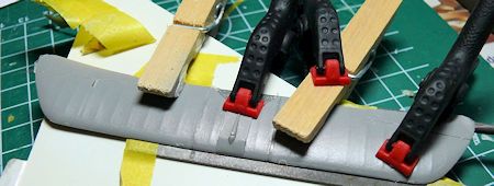 Starting out with the top wing, so it could be set aside and left to fully cure,
I examined the parts, and like most Roden kits, found a tiny amount of flash on
the mating sides. Generally speaking, all Roden kits I've built so far had this
and even though it is sometimes almost invisible, a quick swipe with sandpaper
or sanding stick is enough to remove it. I swiped the mating surfaces along a
sanding stick, and was left wondering how to get the three parts properly lined
up in three dimensions. After a bit of fretting with a piece of glass, I found
out the radiator on the lower part interferes, so I ended up taping two of my
files to a piece of Evergreen, then taping that to a piece of glass. After
carefully lining up all parts and some minor adjustments, the whole thing was
taped down, and some clamps added to the outer wing parts to match the wing
profile -all to reduce sanding on a very visible place! A steel ruler was
pressed against the leading edge to make sure that lined up, and a modest amount
of Tamiya Extra Thin was run along the mating edge, and the whole thing left to
harden for a few days.
Starting out with the top wing, so it could be set aside and left to fully cure,
I examined the parts, and like most Roden kits, found a tiny amount of flash on
the mating sides. Generally speaking, all Roden kits I've built so far had this
and even though it is sometimes almost invisible, a quick swipe with sandpaper
or sanding stick is enough to remove it. I swiped the mating surfaces along a
sanding stick, and was left wondering how to get the three parts properly lined
up in three dimensions. After a bit of fretting with a piece of glass, I found
out the radiator on the lower part interferes, so I ended up taping two of my
files to a piece of Evergreen, then taping that to a piece of glass. After
carefully lining up all parts and some minor adjustments, the whole thing was
taped down, and some clamps added to the outer wing parts to match the wing
profile -all to reduce sanding on a very visible place! A steel ruler was
pressed against the leading edge to make sure that lined up, and a modest amount
of Tamiya Extra Thin was run along the mating edge, and the whole thing left to
harden for a few days.
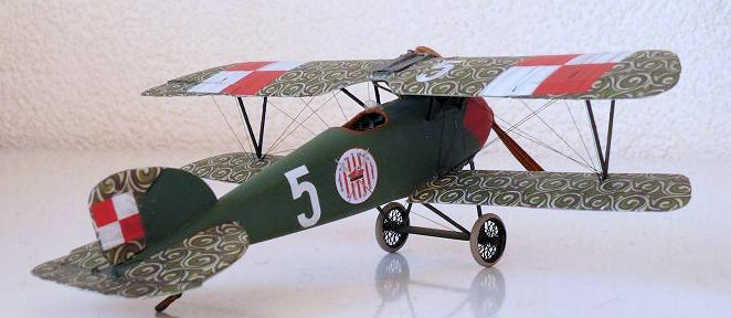
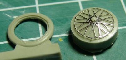 The wire wheels were another matter. I very carefully cut the PE spokes free
from the fret, and was left with the fun task of removing the burrs, without
bending or breaking them! The first one was slightly damaged, unfortunately. The
others went better; I removed the burrs with a sharp scissors. I read that
somewhere on the internet, and it worked remarkably well. Using the provided jig
to bend the outer parts, I simply used a knife blade to remove the wafer-thin
interior of the resin wheels. A quick swipe with sandpaper removed the remnants,
and after a lot of fretting and fussing, the wire disk was installed. The fit is
very tight, making them extremely good looking if you're a photo-etch master,
but slightly less if you are like me and left a tiny burr, denting the rim
slightly. The etched parts really snap into place if done properly, of course
the last one always goes the best! I'm still very happy with how they turned
out, especially after fitting the resin axle, which is also a very good fit. So
far the more notorious of materials seem to fit and finish better than the
standard kit parts!
The wire wheels were another matter. I very carefully cut the PE spokes free
from the fret, and was left with the fun task of removing the burrs, without
bending or breaking them! The first one was slightly damaged, unfortunately. The
others went better; I removed the burrs with a sharp scissors. I read that
somewhere on the internet, and it worked remarkably well. Using the provided jig
to bend the outer parts, I simply used a knife blade to remove the wafer-thin
interior of the resin wheels. A quick swipe with sandpaper removed the remnants,
and after a lot of fretting and fussing, the wire disk was installed. The fit is
very tight, making them extremely good looking if you're a photo-etch master,
but slightly less if you are like me and left a tiny burr, denting the rim
slightly. The etched parts really snap into place if done properly, of course
the last one always goes the best! I'm still very happy with how they turned
out, especially after fitting the resin axle, which is also a very good fit. So
far the more notorious of materials seem to fit and finish better than the
standard kit parts!
With the more challenging parts done, I assembled some cockpit parts and other
small sub-assemblies. The remaining photo-etch interior parts were cleaned up,
and the instrument panels (left, right, and left fuselage half) were installed
with super-glue, as was the rear bulkhead. I had to look at the Squadron blog to
see bigger versions of the pictures that show how to install the parts, since
those in the instructions
 are too small and dark to be useful. The fuselage was
quite badly bent, but the photo-etch rear bulkhead and resin forward bulkhead
seem to provide quite a rigid assembly. Again,
the update-parts that generally cause most of the extra work in other
kits, fit better than the kit itself!
are too small and dark to be useful. The fuselage was
quite badly bent, but the photo-etch rear bulkhead and resin forward bulkhead
seem to provide quite a rigid assembly. Again,
the update-parts that generally cause most of the extra work in other
kits, fit better than the kit itself!
After the top wing had cured, I cut the ailerons out with a small scissors
stolen from my girlfriends toolbox for making postcards. The plastic is very
thin and soft, so after some sanding, the new ailerons with scalloped edges fit
quite well. Obviously one can also simply use a roll of sandpaper and scallop
the trailing edge of the existing ailerons, but since I'm supposed to review
this kit and see how it all fits together I used the provided parts. A small
advantage is that you can deflect them too, if you wish. The scalloped edges on
ailerons and elevator are unique to the series 253, at least, that's what the
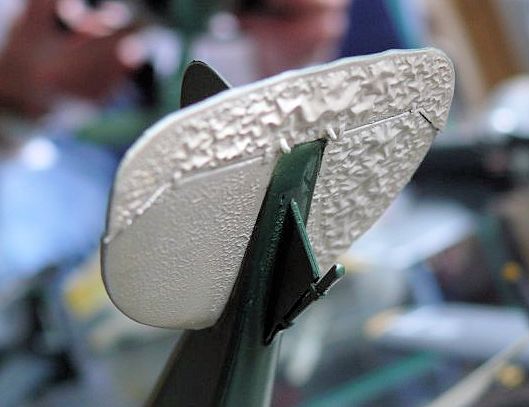
Datafile says. Since I was working on the wing anyway, I carefully scraped off
the moulded on radiator detail, sanded the remaining hump somewhat thinner, and
installed the photo-etch replacement faces. As moulded in the kit, the bottom
one had a large mould defect, straight in the detailed part. Oh well, scrape,
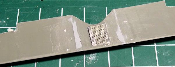 sand, and install photo-etch, and nothing to be seen. Obviously if you build the
standard Roden kit you're left on your own how to fix that ;-)
sand, and install photo-etch, and nothing to be seen. Obviously if you build the
standard Roden kit you're left on your own how to fix that ;-)
After that I pre-drilled all the 0,3mm holes for the rigging. I also enlarged the dimples in the fuselage halves for the bottom wing, and it appears the moulds are damaged, as some holes are actually some sort of pins that appear broken off, so I cut those off and re-drilled the holes using an 0,7mm drill bit. I also checked the length of the wing struts against the plans in the Datafile, and they are nearly there, but not quite... But then, so were the struts of nearly every other Roden kit I built, and none of them had struts that were simply snapped in place! ;-) It appears Roden used the same plans to design the kit, as most parts match the drawings almost exactly -the fuselage appears a tiny bit skinny, but I mostly use plans to build this kind of kits on, not for the quest for accuracy.
Since by now the wing had sufficiently hardened, I applied some Mr Surfacer to
the joint and set that aside to dry. I also applied a dab of that stuff on the
large sink mark on the rear fuselage. After the Surfacer had set it was
wet-sanded with 400 grit, using my home-made sanding sticks. I use a thin narrow
strip of Evergreen 0,5mm and glue a strip of sandpaper on that. I then trim the
edges, and voilà, a sturdy yet flexible sanding stick that will fit neatly in
between the delicate wing ribs. Careful sanding of the mating surfaces and
equally careful glueing pays off here; the top hardly needed filler, and the
small step at the bottom was taken care of with sanding and some more Mr
Surfacer. Though primer will be the ultimate test, a dab of paint brushed on
showed it looked pretty good so far.
Since the ailerons are separate and can thus be posed, I thought it a neat idea
to pose the elevator and rudder as well. I used the most simple method for this;
using the fine edge of my JLC razor saw I cut the angled parts, then scored the
remaining recessed line lightly with a Tamiya scriber, and then simply bent them
at the desired angle and applied some Extra Thin to fixate.
The only tricky parts are sawing at the proper angle, and being sure not to bend
the control surfaces too
 far so they'll break! Fortunately, while thin, the Roden plastic is quite flexible. Also fortunate is that Roden provides extra
parts to practice on. In the case of the D.III you get a (German) OAW rudder and
the normal non-scalloped tailplanes/elevators. Since those parts turned out
pretty good I kept them aside for if I were ever to build a normal German
Albatros!
far so they'll break! Fortunately, while thin, the Roden plastic is quite flexible. Also fortunate is that Roden provides extra
parts to practice on. In the case of the D.III you get a (German) OAW rudder and
the normal non-scalloped tailplanes/elevators. Since those parts turned out
pretty good I kept them aside for if I were ever to build a normal German
Albatros!
By now I had finally run out of things to hack up and sand away at. So it was
time for paint. The whole kit was first degreased, and then the interior parts
were airbrushed with Vallejo grey urethane primer, which dries quickly, so I was
able to paint the top colours in the same airbrushing session. I used a mixture
of white and desert sand to get a light-buff colour which would be the base to
get the wood grain on later. The other parts were painted their respective
colours, with a bit of guesstimate, as not all details are indicated in the
instructions.
The wood grain was done by a small dab of dark brown oil paint (I use Winsor &
Newton) and streaking that with a stiff brush, only damp with Humbrol thinner. I
put the oils on a tissue to help soak some of the oils in there, so they don't
take weeks to fully dry, but, being oils, there are still great to manipulate.
After a week or 2 I hand-brushed a thin coat of Tamiya Clear Yellow over the
interior, the instrument panels were done with a 50-50 mix of Clear Yellow and
Orange to make them stand out a bit. After that was dry, it was time to start
closing the fuselage. The PE rear bulkhead is a good help for aligning the
fuselage, which in my kit was banana-shaped, so had to be glued in sections. I
used a Tamiya Scriber to scribe a line inside the fuselage where it would go,
and the fuselage closed without gaps. After it had set I ran thin CA behind it
just to be sure. The forward part kind of bowes inward, interfering with the fit
of the top decking and typical Öffag-nose. I dry-fitted the resin forward
bulkhead and found it a perfect guide to prevent that. After using my fingers to
close the fuselage, I inserted the bulkhead and added clamps, then positioned
the bulkhead in the right position and ran Tamiya Extra Thin along the fuselage
seam. Since I only had the bulkhead painted up in basic colours it was not glued
yet so it would be easier to paint later. I also found out at this stage I'd
forgotten the instrument decals... fortunately they are still accessible without
the 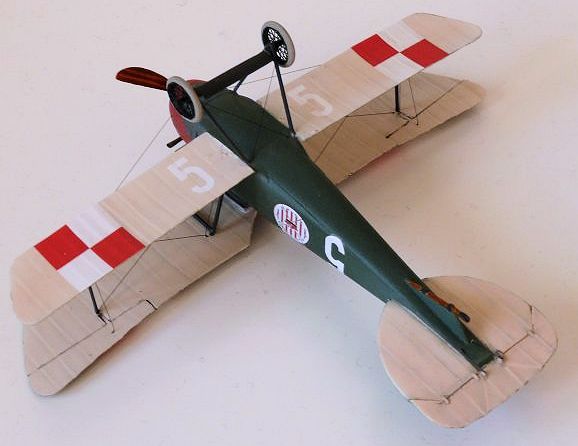 top decking in place, so they were added first and some parts given a wash
with dark grey for some extra depth and a drybrush with light grey here and
there.
top decking in place, so they were added first and some parts given a wash
with dark grey for some extra depth and a drybrush with light grey here and
there.
After that it was a matter of assembling all the cockpit parts, except for the
seat, which I'd save for later as I usually do, and sanding the mating edges a
bit to get the top decking to fit. This was also glued in 2 stages, the area
surrounding the cockpit first. With careful dryfitting, the fit is decent,
though still in need of some extra sanding and probably some filler. I also
dryfitted the engine at this time, and found it got too low for the exhausts to
protrude between the full cowling I intended to fit. When the nose is added, the
engine is also too far backwards for the exhausts to fit, so I moved it forward.
After all, with the full engine cowling in place, the only purpose it serves is
provide a mounting place for the exhausts. I also found the engine, in addition
to the bulkhead, spreads the forward fuselage enough so the contours seem to be
quite good for the nose to fit. The only drawback of raising the engine, is that
the prop shaft does not line up with the hole in the nose, though that should be
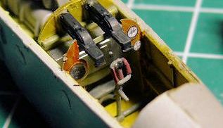
an easy fix later. Somehow I managed to break one of the machine-guns loose with
the decking now firmly in place, so I used a cocktail stick to dab CA glue where
it would go and stick; however, one of them protrudes slightly more towards the
pilot now -at bit unfortunate, as they're pretty much the only thing that can be
seen of all the nice resin details! The carefully painted bulkhead is so far
forward that it's pretty much invisible. I was glad I painted the large box,
which I presume is the ammo-box, natural metal, so it'll still show up in that
dark area. Probably until I fit the top wing, that is! Earlier I had glued the
machine-guns to the bulkhead, only to later discover the larger versions of the
pictures to install the PE and resin... by that time I found out I had glued
them upside down, as well! Not much else to do but take the loss and glue the
forward part of the cowling in place, but not after sawing off much of the
forward part of the engine.
 With the nose parts well set and dry, I used sanding sticks to get the fuselage
nose to match the contours of the nose cap, without over-sanding or losing the
contours. The Roden plastic is rather soft, so this is rather easy to do!
Eventually I got it pretty right, though no doubt a coat of primer later will
show some flaws, as it always does.
With the nose parts well set and dry, I used sanding sticks to get the fuselage
nose to match the contours of the nose cap, without over-sanding or losing the
contours. The Roden plastic is rather soft, so this is rather easy to do!
Eventually I got it pretty right, though no doubt a coat of primer later will
show some flaws, as it always does.
I elected not to use the PE parts for the louvres. The PE seems to be stainless
steel and is very durable and springy, making it very sturdy for the spoke
wheels, but I kept having to spot-glue the seatbelts in place, and messed up too
many of the louvres, not only with bending, but also with cleaning them up. They
would have been better served in the more easily bent (and cleaned up!) brass
-which would probably also have resulted in thinner access panels. I found them
too thick and stood quite proud, so I kept the plastic details.
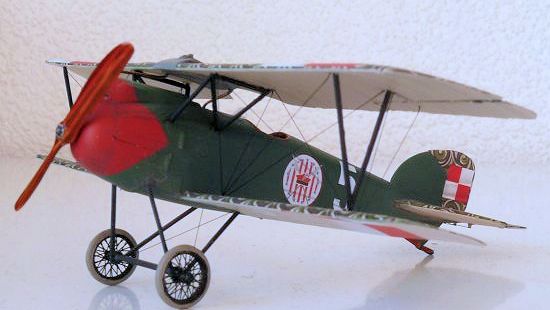
Then it was time for the winter cowling. The pictures I found of Coopers
aircraft showed it with the cowling, and I think it sets it apart from it's
German counterparts, too. The cowl is typical Roden, thick and with
not-quite-matching mating surfaces. Since I had left all the accessories off the
engine -using it basically only as a way to get the exhaust stacks in place- it
got quite close to fitting. I only had to cut the intake manifolds off, and
since those are on the closed side of the cowl you can't see them anyway. After
that the cowl fit well enough, though it'll still require some sanding and
filling.
 Comparing all the detail parts with the 1:1 example built by Koloman Mayrhofen,
the cockpit detail is a bit simplified; there is a lot more going on in there
for those inclined to go super-detailing. Two notable omissions are the cut-outs
in the floor for the rudder pedals, and the H-shaped frame that the seat rests
on. Those inclined to do so can also drill lightening holes in the seat and use
the lap belts only -of course I found the pictures only after I had completed
mine!
Comparing all the detail parts with the 1:1 example built by Koloman Mayrhofen,
the cockpit detail is a bit simplified; there is a lot more going on in there
for those inclined to go super-detailing. Two notable omissions are the cut-outs
in the floor for the rudder pedals, and the H-shaped frame that the seat rests
on. Those inclined to do so can also drill lightening holes in the seat and use
the lap belts only -of course I found the pictures only after I had completed
mine!
Also, it appears the instructions have the machine guns upside down, when
looking at pictures of Schwarzlose machine-guns. Which actually means I got mine
in OK, as I had them glued upside down according to the instructions! ;-) The
curved side goes on top
One of the things that always seems to dog my WWI builds, no matter how much I
try, is some form of misalignment. The fit is usually tricky, and the subject
complex, and somehow I always manage to get a tiny part out of alignment,
resulting in a wing that is not-quite as it should be, or undercarriage that
needs some bending and fiddling to get it to look decent.
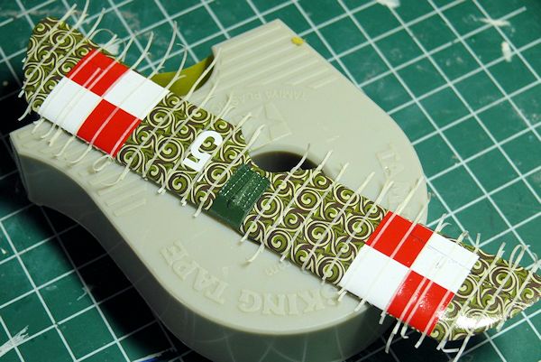
So for this model, where the lower wings attach only on some tiny dimples and
equally tiny pegs, I tried something more scientifically. I happened to have the
Datafile on the Austrian Albatros, which contains some very good scale drawings.
I used those to build my own jig, making sure the lower wings are
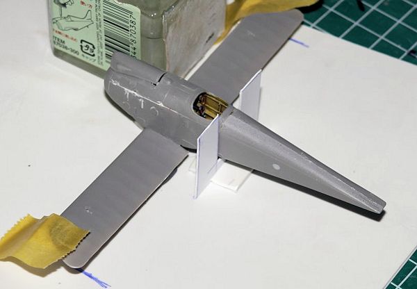 straight, yet
also have about 1 degree of dihedral. After an hour of aligning and checking all
angles, I ran some Tamiya Extra Thin along the mating surface and did not dare
touch it for a few days. In the end, however, the wings are so thin and
flexible, that at this stage of writing I'm not sure how it will look
eventually.
straight, yet
also have about 1 degree of dihedral. After an hour of aligning and checking all
angles, I ran some Tamiya Extra Thin along the mating surface and did not dare
touch it for a few days. In the end, however, the wings are so thin and
flexible, that at this stage of writing I'm not sure how it will look
eventually.
After all that had set I was rewarded with what appear to be straight wings, so
it was time to check the length of the upper struts and expand the jig later to
accommodate the top wing. In some reviews I noted comments that the cabane
struts are too long, resulting in either a top wing that is too high, or too
short V-struts. Another review of the basic Roden Albatros noted the reverse, so
I guess I had to find out myself!
Curiously, a probable source of this discrepancy is that, after having a look
online at the Roden instructions for all D.II and D.III models, on all the
D.IIIs part 11C is indicated to be used for the cabane struts. This part is
about 2mm longer than 9C, which is indicated in the Encore kit (albeit with a
slightly different font, indicative of a correction?) as well as the Roden D.II.
Part 9C nearly matches the Datafile drawings, being slightly too short, and I
have no clue what 11C is supposed to be for -perhaps the W.4 float-plane, as the
D.I with it's higher wing uses a different arrangement for the cabanes. 11C is
slightly too long, so make your pick! Finally, after a quick comparison to my
older Pegasus kit, which “looks” right with regard to the wing position shows
the cabane struts are equal in length, and the V struts of the Roden kit to be
longer. Obviously you can't really apply those Pegasus-kit measurements to the
Roden kit, as there may be (and actually are) variations in fuselage height and
wing thickness (the Roden wing is thinner, for example, but the kit appears to
have been designed from the Datafile plans, too)
I cleaned up all the parts so I had some options and could perhaps combine the
struts to make the top wing fit well.
Then some Mr Surfacer 500 was brushed on the fuselage seams, and after letting
it harden for a few days it was sanded smooth. After that I added the tailplanes,
whose contours were adjusted for a better fit. A small oddity is that the
forward edge has locating pins, which are also shown in the instructions, but
they are not present on the actual kit fuselage. I simply cut them off and drew
a pencil line on the fuselage sides, again using the Datafile plans for
reference. Even with adjustments, there's a small gap, which I filled with
several layers of water-based Vallejo putty, as this can be swept with a wet
finger and cloth, and does not require sanding, which would damage the details
on the tailplanes. At this stage I
also noticed I forgot to remove some louvres and a boarding step, all nicely
indicated in the instructions. These were duly removed, and since the sanding on
the nose end had destroyed some panel lines, those were rescribed too. I added a
central vertical line to the nose cap, as pictures show it was divided in two
parts. There should also be a some small vent holes near the bottom, but I was
unfortunately unable to properly scribe those in the multiple curved nose.
The last bit of PE to be installed was the landing gear strap under the nose. As
sanding the centre seam had pretty much obliterated the moulded on straps, I
drilled the mounting holes for the gear struts a bit deeper to mark their
position, and then sanded them off. I very carefully removed the PE part from
the fre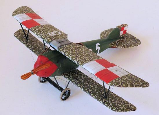 t, but as the instructions indicate, it is oversized (why???), so you're
required to cut it in half, pretty much distorting it and making straightening
it back out again an (in my opinion) avoidable chore.
The stiff nature of the PE does not help with placing the part either,
the straps, once straightened out, are relatively easy to apply. The squares
where the struts go into should have a gentle curve to match the fuselage, but
the PE is so stiff getting a 1,5x1,5mm square to confirm proved impossible for
me. After an hour of fussing and cursing I simply glued them in place, but they
are not as flush as I would like to see. I'd recommend sanding the straps off,
and simply replacing those with some stretched sprue -leaving the moulded
squares intact. Unless you're a PE-maestro, which I'm obviously not, this would
be an easier method. At this time the tail skid fairing and vertical tail were
also, rather uneventfully, glued on and fixed with tape to keep them in
position. This was then left to dry. Those parts, like the horizontal tailplanes,
have moulded on pins, but no corresponding holes in the fuselage. I cut the pins
off and wrapped a thin strip of masking tape around the rear fuselage to make
sure they all aligned. Even though they are simply butt joined, they don't have
to hold a lot, unless you intend to swing the model around by its tail!
t, but as the instructions indicate, it is oversized (why???), so you're
required to cut it in half, pretty much distorting it and making straightening
it back out again an (in my opinion) avoidable chore.
The stiff nature of the PE does not help with placing the part either,
the straps, once straightened out, are relatively easy to apply. The squares
where the struts go into should have a gentle curve to match the fuselage, but
the PE is so stiff getting a 1,5x1,5mm square to confirm proved impossible for
me. After an hour of fussing and cursing I simply glued them in place, but they
are not as flush as I would like to see. I'd recommend sanding the straps off,
and simply replacing those with some stretched sprue -leaving the moulded
squares intact. Unless you're a PE-maestro, which I'm obviously not, this would
be an easier method. At this time the tail skid fairing and vertical tail were
also, rather uneventfully, glued on and fixed with tape to keep them in
position. This was then left to dry. Those parts, like the horizontal tailplanes,
have moulded on pins, but no corresponding holes in the fuselage. I cut the pins
off and wrapped a thin strip of masking tape around the rear fuselage to make
sure they all aligned. Even though they are simply butt joined, they don't have
to hold a lot, unless you intend to swing the model around by its tail!
By then real life interfered and the Albatros could thoroughly dry for a few
weeks, though mostly unintended! After a bit of sanding on the tail skid and
fin, I added thin strips of decal (some of those black edges that some companies
print around the sheets are especially useful) to represent the missing ribs on
the top wing joint. Also, with the airframe now fully complete, I drilled the
last remaining rigging holes and after cleaning the model and top wing it was
airbrushed with Humbrol primer, number 1.
| COLORS & MARKINGS |
Then it was time for paint. After fixing some small blemishes the primer showed,
I first mixed Revell Aqua Skin Tone with a lot of white, and did the
undersurfaces of both wings and tailplanes. The latter are shown as green on the
instructions, however, the top is also shown as green, but there should be the
sworl decals on top, obviously. I masked that off and painted the nose part
white, then found out my red paint had dried out, but rather enjoying the
painting moment I had, I went ahead with the green.
I enlisted the help of the MM forums for the green, as I did not have access to
the indicated Vallejo colour and hoped someone could compare it with other
brands I could get. I also realized Eduard does the model in 1/48, so I
downloaded their instructions and found they recommend RAF Green. After a bit of
testing of Lifecolor RAF green and Humbrol 163 with the same name, with the rest
of the colours I went with the Lifecolor version.
A few days later, with a new pot, cube, tin, whatever one calls those square
Aqua “containers” of Ferrari red in hand, and some difficult masking of the nose
later, I painted the nose red and did some very small touch-ups on the green.
 Unfortunately, when applying the gloss-coat was when my ubiquitous paint
disaster happened. I have used a spraycan of gloss earlier on other models with
the same paints, but this time it ate through the painted surfaces and attacked
the Humbrol primer, causing all my work to simply fall of the model in large,
bubbled flakes....
Unfortunately, when applying the gloss-coat was when my ubiquitous paint
disaster happened. I have used a spraycan of gloss earlier on other models with
the same paints, but this time it ate through the painted surfaces and attacked
the Humbrol primer, causing all my work to simply fall of the model in large,
bubbled flakes....
I put the model away to contemplate my next steps... in the end Mr Color thinner
dissolved all remaining paint, leaving me with a clean model -unfortunately it
also dissolved the Mr Surfacer I used for filling, so that was re-done and some
details (like the small holed squares near the cockpit and nose) were redone
using old photo negative material. I also re-applied the decal strips to the top
wing mating, and re-primed the model using Mr Surfacer 1200 this time. Then it
was basically a repeat of the previous painting steps, and playing it safe, I
used Tamiya X-22 acrylic gloss, which performed wonderfully and made for a very
glossy model. It may not be cheap, but the frustration of having all paint fall
off on a complex paint scheme isn't worth it, so the X-22 will be my gloss of
choice from now on.
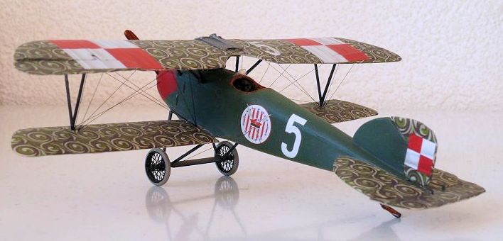
Then it was time for decals. These are by Cartograf -enough said!
My only caveat with them has to do with two things: the pattern is very
repetitive (i.e. left/right wing are mirrored, elevator and ailerons continue
the pattern while they were separate parts) and though they are sized to the
model, I was left with some short areas, probably due to the fact that I
animated the control surfaces. Fortunately some extra material is provided, and
duly used on the top wing centre section cut-out near the radiator, the
elevator, and wing tips, where some had flaked off. I very sparingly used some
Daco medium decal solution on complex areas like the wing tips and centre
section cut-out, but otherwise none is needed. Being pre-sized does make
decalling a breeze, as everyone who has ever done a Lozenge-covered model
without pre-sized decals can attest!
 Re-glossing the model, I used 0,5mm tape to mask off all the wing and tail ribs
for some shading with Tamiya Smoke -not realistic per sé, but I liked the look
on some other models I saw and wanted to try it. I'm not a great fan of masking
over decals, but only had one very tiny bit pulled away with the tape -a
testimony to their quality. I also masked off the radiator and painted it Revell
Aqua “Steel”. The same brand, but Coal Black this time, was used to paint all
the struts and wheels. After a few touch-ups and a light misting of Linen colour
on the under surfaces (where the Smoke-effect was a little too stark for my
taste) I applied a dark oil wash to the nose area and radiator, and gave
everything a matt coat (also Revell Aqua) so I could proceed with the final
asse
Re-glossing the model, I used 0,5mm tape to mask off all the wing and tail ribs
for some shading with Tamiya Smoke -not realistic per sé, but I liked the look
on some other models I saw and wanted to try it. I'm not a great fan of masking
over decals, but only had one very tiny bit pulled away with the tape -a
testimony to their quality. I also masked off the radiator and painted it Revell
Aqua “Steel”. The same brand, but Coal Black this time, was used to paint all
the struts and wheels. After a few touch-ups and a light misting of Linen colour
on the under surfaces (where the Smoke-effect was a little too stark for my
taste) I applied a dark oil wash to the nose area and radiator, and gave
everything a matt coat (also Revell Aqua) so I could proceed with the final
asse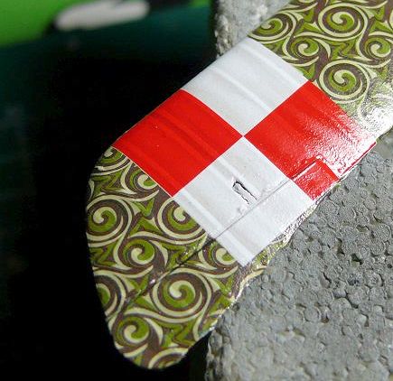 mbly. The only surfaces not shaded, matt coated and decalled were the lower
wing under surfaces, since I'll have to pull rigging wires through them and the
decals will aid in covering up the holes for that. These will be done once the
rigging is in place.
mbly. The only surfaces not shaded, matt coated and decalled were the lower
wing under surfaces, since I'll have to pull rigging wires through them and the
decals will aid in covering up the holes for that. These will be done once the
rigging is in place.
Finally the remaining small parts like propeller and wheels were painted and set
aside for assembly.
| CONSTRUCTION CONTINUES |
In this case I started with the undercarriage, which is quite fiddly. I used
Tamiya Extra Thin to secure the rear struts in place, inserted the axle, and
carefully lined everything up. The Extra Thin allows for some movement, while
still drying fast enough to prevent you from having to hold the parts all
evening! This was left to dry overnight, and then the forward legs were
super-glued in place, as was the axle. The rear struts were also given a small
dab of glue.
Then it was time for one of those biplane milestones: mounting the top wing.
Since I had earlier found out the struts did not quite match the drawing, and a
dry fit indicated the wing height did not “look” right either, I checked the
measurements of the fuselage to the Datafile drawing. Pretty much a good match,
so I shortened the V-struts by about 1mm -not a lot, but it makes a big visual
impact. The very flexible lower wings (which, before mounting the top wing, had
a bit too much dihedral) would hopefully compensate a bit if I didn't get
everything exactly right. I glued the V-struts to the top wing, and made a
temporary jig from a piece of foam, with some cocktail sticks to prevent the
wing from tilting. Re-checking my meas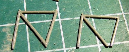 urement I found the interplane and
fuselage to top wing gap pretty well according to the drawings. I then tested
the cabane struts, and like I found earlier, the indicated part 9C is too short,
and 11C too long. Since shortening something that is too long is generally
easier, I took measurements from the Datafile, marked the bits to be cut with
Tamiya tape (also to stick the part to my cutting mat, to prevent it from moving
or, worse, breaking) and then using a JLC very fine razor saw carefully cut
about 1,5mm off the undersides of the cabane struts. The rearmost has a diagonal
bracing strut, so this was lightly fussed with a scalpel and re-glued with Extra
Thin cement. Fortunately the Roden plastic is quite flexible so this is very
doable. Very carefully I sanded the ends back into a somewhat tapered shape, and
I then added tiny dabs of sprue so they would fit the holes in the fuselage and
left them to dry for some time, after which they needed re-painting since my
actions had damaged the paint.
urement I found the interplane and
fuselage to top wing gap pretty well according to the drawings. I then tested
the cabane struts, and like I found earlier, the indicated part 9C is too short,
and 11C too long. Since shortening something that is too long is generally
easier, I took measurements from the Datafile, marked the bits to be cut with
Tamiya tape (also to stick the part to my cutting mat, to prevent it from moving
or, worse, breaking) and then using a JLC very fine razor saw carefully cut
about 1,5mm off the undersides of the cabane struts. The rearmost has a diagonal
bracing strut, so this was lightly fussed with a scalpel and re-glued with Extra
Thin cement. Fortunately the Roden plastic is quite flexible so this is very
doable. Very carefully I sanded the ends back into a somewhat tapered shape, and
I then added tiny dabs of sprue so they would fit the holes in the fuselage and
left them to dry for some time, after which they needed re-painting since my
actions had damaged the paint.
This bit of effort paid off very well, as I was rewarded with properly fitting
cabane struts! Hurray!
Of course my bit-of-foam-with-cocktailstick-jig was not quite suited to final
assembly of the wing, so after some head-scratching I came up with something
simple. I put the model in my temporary jig again, and simply ran a bit of
narrow Tamiya tape over the nose, top wing, and rear fuselage. This way the wing
would stay put, could still be positioned properly, and would leave me a free
hand to push it down a bit too
 far, snap the cabane struts in their mounting
holes, and apply a dab of thin CA to the mounting positions. My free hand was
even capable of adding a bit of accelerator so I could let go -and I was
rewarded with my first Roden model that appears to have everything aligned
properly!
far, snap the cabane struts in their mounting
holes, and apply a dab of thin CA to the mounting positions. My free hand was
even capable of adding a bit of accelerator so I could let go -and I was
rewarded with my first Roden model that appears to have everything aligned
properly!
I left it to harden for a night, and then added the rigging wires to the top
wing and fuselage, and left those alone, too, to make sure they would be fixed
well before pulling them tight. After tightening them using clothes pegs and
using CA to fix them in place. Unfortunately one of the inner wires near the
cabane struts did not want to tighten -a bit of heat made it a bit better, but
it appears the thin CA ran a bit downward, gluing the 2 wires a bit further
together then I wanted, giving it a bit of a curve as it starts at the top wing.
That makes it look a bit slack, but it isn't really -it just looks a bit odd.
Since I only noticed after cutting the ends off, there was no way to fix it, so
I applied a bit of heat with a soldering iron, and it came out slightly better,
but still odd. Moving on, I used a fine brush to dab a bit of nearly dry (thick)
paint in the small holes, and glossed the lower wing. After letting it dry
overnight, I applied the decals, then, trying my luck, I carefully masked the
ribs over the unvarnished decals and did the shading (this time mixing 1:1 clear
gloss to the Tamiya Smoke make it stand out less and avoiding having to
overspray with base colour to reduce contrast like I had to on the top wing and
tail), using a hair dryer to speed drying, then immediately removed the masking
(no pullups -brilliant!) and applied flat Revell Aqua varnish as per the rest of
the model. Thanks to th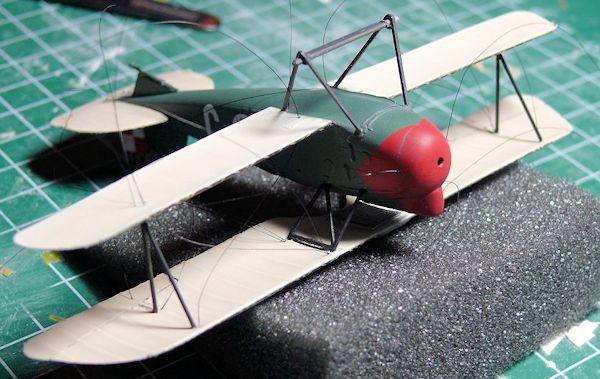 e quick drying time of the acrylics, I was able to do all
that in one evening.
e quick drying time of the acrylics, I was able to do all
that in one evening.
After that it was time for the last small bits, of which, almost like a modern
jet fighter, there are quite a bit. I re-glued the seat in (it had broken out),
painted the leather coaming, cut and added the acetate windscreen (thanks to the
MM forums for tips -I used clear varnish to fix it in place after first bending
it slightly curved to match the fuselage contours) and had a lot of fun cutting
tiny pieces of stretched sprue to equal lengths to make the gun blast tubes
protruding through the winter cowling. They're so tiny, I was unable to drill
the ends out. Cutting them at an angle and using CA glue to add them to the
nearly complete model was nerve-wracking enough!
By now the only bits left to add or make were the radiator pipes, wheels,
propeller and exhausts. I'd painted
the propeller earlier, and the radiator piping was bent from brass rod with the
drawing from the Datafile as a guide, and fretted with a bit to get them to fit.
They were probably green or black, but I liked the brass colour, so left them
bare. The exhausts were painted Mid Stone, dry-brushed with black, and given a
filter with blue. I also painted the insides black for depth and soot. I then
removed them all at once from the pour block using a JLC saw and managed to
install them quite decently. As a final touch I rubbed them with some lead
pencil. The wheels were then installed, and at that moment my parts bag -save
for all the extra stuff Roden gives you- was empty. I took my customary beer,
took pictures, turned my build notes into this
review, and called her all done!
| CONCLUSIONS |
 basic cockpits. It
does come at a price; $24,50 for a small 1/72 WWI biplane is not exactly a
bargain, but then, most modellers who have used aftermarket decals, resin, and
photo-etch will probably be aware that the cost of these items will quickly add
up, too. One thing I possibly would like to have seen would be some extra decal
options -many Polish and Austro-Hungarian Albatrosses were quite similar in
their markings.
basic cockpits. It
does come at a price; $24,50 for a small 1/72 WWI biplane is not exactly a
bargain, but then, most modellers who have used aftermarket decals, resin, and
photo-etch will probably be aware that the cost of these items will quickly add
up, too. One thing I possibly would like to have seen would be some extra decal
options -many Polish and Austro-Hungarian Albatrosses were quite similar in
their markings.
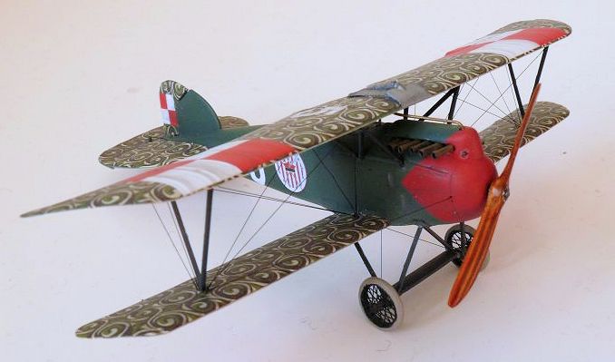
I guess it is up to the individual to decide if it's worth the asking price:
I've tried to show what can be done with it, and it definitely looks very neat
next to my Roden Fokker D.VII with Lozenge decals!
If you think it's worth it, go get one, and have fun building this very nice and
unusual version!
As a final word, thanks to Scott
for giving me the opportunity to build this kit, even though he was probably
aware I am a very slow builder so it would take a while before it would be done!
| REFERENCES |
-Squadron Website/Blog
-Windsock Datafile on Albatros Öffag series
-Google for additional pictures of Polish Albatrosses. (try searching in Polish
-it'll turn up wonderful stuff!)
February 2015 If you would like your product reviewed fairly and fairly quickly, please
contact the editor or see other details in the
Note to
Contributors.