Revell 1/72 Fokker Eindecker E.III
|
KIT # |
H-4111 |
|
PRICE: |
$ |
|
DECALS: |
One aircraft |
|
REVIEW : |
|
|
NOTES: |
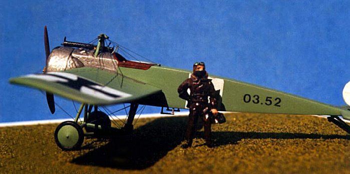
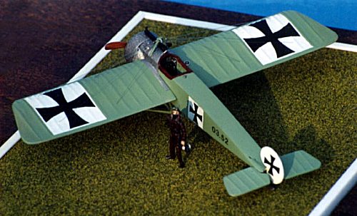
"SNOWBIRD"
FOKKER E.III "EINDECKER"AUSTRO-HUNGARIAN AIR SERVICE
FLIEGERKOMPAGNIE 19 - HAIDENSCAFE AIRDROME
FEBRUARY - AUGUST 1916
|
HISTORY |
Snow Bird was name given to this Austro-Hungarian Air Service Fokker A. III (German designation E. III) number 3.52, flown by Oberleutnant Ludwig Hautzmayer. This aircraft was assigned to Fliegerkompagnie 19 (Flik 19) at Haidenscafe aerodrome on the Isonzo Front in February, 1916. It served with this squadron until it was in a collision with another Fokker A. III (3.44) in August, 1916. Both pilots were attacking two Italian aircraft at the time and were able to land their aircraft without severe injury. Snow Bird, however, ceased from being Fokker Scourge and became in its own way Fokker Fodder. Overall, Snow Bird was credited with seven combat kills, five by Oberleutnant Hautzmayer. Most of its service duty was spent in strafing maneuvers in support of the Austro-Hungarian troopsalong the Italian Front. The overall green was confirmed to aerohistorian Dr. Martin O'Connor by the revered Austrian naval pilot Gottfried Banfield, who had flown several Eindeckers in such paint schemes.
|
THE KIT / CONSTRUCTION |
Notes on the assembly:
I used the German Revell kit H-4111 of the FOKKER EINDECKER E. III as a starting point. From there work commenced in subassemblies, which are described as they progressed below.
Cockpit:
Steel tubing framework was buiIt using like-sized stretched sprue. Control column and rudder bar were assembled with soldered wire. The seat and empty cartridge box were constructed of various sized sheet plastic.
A Bosch ignition switch was made with a Waldron punched plastic disk and fine wire, and attached to the upper left of the empty cartridge box. The fuel pressure pump was made of an 18 gauge hypodermic needle and wire stock (this was soldered and krazy glued).
 Three
instruments were made by cutting small sections of hypodermic needles (various
gauges) with a Dremel tool and fiber cutting wheel. (Please use safety glasses 1
f you attempt to do this, hypos are made of stainless steel and will leave very
sharp shavings. I used safety glasses in addition to a large magnifying lens. )
After the gauges were cut, they were sanded and filled with white glue until
just the front of the gauge showed. After the glue dried, they were treated to a
drop of white paint and glued to the appropriate locations.
Three
instruments were made by cutting small sections of hypodermic needles (various
gauges) with a Dremel tool and fiber cutting wheel. (Please use safety glasses 1
f you attempt to do this, hypos are made of stainless steel and will leave very
sharp shavings. I used safety glasses in addition to a large magnifying lens. )
After the gauges were cut, they were sanded and filled with white glue until
just the front of the gauge showed. After the glue dried, they were treated to a
drop of white paint and glued to the appropriate locations.
The fuel gauge was mounted outside of the cockpit just ahead of the cabane strut. I built up the existing nodule and drilled an appropriate hole for the gauge. The rev counter and fuel pressure gauges were cemented to the fuselage tubing as shown in reference books.
Seat belts were cut from glossy brown auto striping tape and sanded to cut down the gloss. They were then attached to seat belt buckles from Tom's Modelworks German Interior photoetched sheet and cemented to the seat.
I should add that in order to get enough room for the rudder bar and empty cartridge box, I had to cut away a good deal of the landing gear strut placement. This was done by premeasuring the strut assembly, carefully cutting the struts, and gluing the center cut piece before assembling the strut. The interior was then cut away using a square cutting Dremel bit in the Dremel tool.
Engine and propeller:
The basic kit engine block was used after sanding the cylinder heads flat and installing cylinder chamber outlet valves made of 18 gauge wire. I added a 2-mm piece to the front of the crankcase and drilled nine holes at the base of each cylinder with a #80 bit. I then glued push rods made of 28 gauge wire into each hole and then to the appropriate outlet valve. Small bolt heads on the crankcase were simulated with a drop of epoxy applied with a sewing needle.
The propeller had to be cut on each side of the boss and a 1-mm sect i on of sheet plastic was added to each half in order for the propeller to meet scale specifications. I added a photoetched propeller boss from FotoCut and used 18 gauge wire for the center propeller shaft and 26 gauge wire for the attachment bolts. I also cut out the inside of the engine cowling cover to accommodate the built-up engine.
Fuselage and wings:
 I added
a 5 mm section (built from sheet plastic) to the fuselage rear to align with
scale drawing in Windsock Datafile 15 - FOKKER E III by P. M. Grosz. I drilled
out location holes for the main fuel tank fill cap and reserve tank fuel cap. As
previously mentioned I drilled out for the fuel gauge, in addition to drilling
out all landing and flying wire location holes.
I added
a 5 mm section (built from sheet plastic) to the fuselage rear to align with
scale drawing in Windsock Datafile 15 - FOKKER E III by P. M. Grosz. I drilled
out location holes for the main fuel tank fill cap and reserve tank fuel cap. As
previously mentioned I drilled out for the fuel gauge, in addition to drilling
out all landing and flying wire location holes.
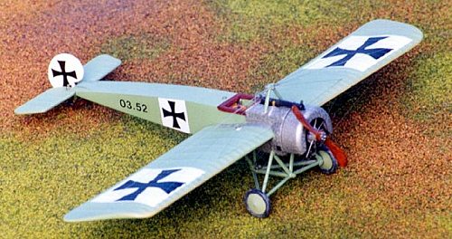
The main wing plan was cut and sanded at the wing rakes to align with scale drawings. (The kit wing plan is visibly too square at the front rakes in addition to being about 5-mm too long. ) The elevators were cut free from their attachment piece and an 18 gauge piece of wire was glued in its place. This simulated the non-fixed elevators better and was cemented to the rear of the fuselage after adding two control horns from wire stock.
The entire rudder had to be reshaped to match scale drawings in Windsock and Aircraft Archive publications. (The kit rudder is too large and should be more rounded at the leading edge.) I held off attaching the rudder until after the rear landing skid assembly was installed. Appropriate holes were now drilled for control wires and tail skid braces.
Undercarriage and landing skid:
The kit's main undercarriage assembly was used after sanding off mold lines and slowly thinning down the braces with file and sandpaper so as to present a more scale appearance. (They are still a touch large, but I left them that way for strength. ) To this assembly I added wing warping controls and landing and flying wire attachment points from sheet plastic and stretched sprue.
The landing skid assembly was completely rebuilt using only the kit's skid from the original piece. I constructed the skid/rudder attachment braces from 18 gauge wire and glued the assembly into predrilled attachment holes. The bungee cord shock absorber was cut from the smallest gauge shielded wire I could find. I stretched this to the thinnest piece I could attain and then soldered it. I then bent the soldered wire to the desired angle, cut, and cemented it to the brace assembly. The tail skid and rudder were lastly added, after which I glued the main undercarriage assembly to the fuselage.
The cabane strut was attended to next. After sanding to a more scale thinness (again I had to opt for strength) and predrilling wing warping and landing/flying wire holes, I cemented the cabane st rut to the fuselage. The wing warping roller-pulley was constructed from a Waldron punched disk and 26 gauge wire and attached to location holes. The landing and flying wire attachments were constructed by tightly wrapping 34 gauge wire around a #80 drill bit and cutting to proper length before attaching them to location holes.
Machine gun, rigging, compass, etc.:
 After the
main assembly I directed my attention to the additional details to make Snow
Bird come alive. The machine gun is part kit (breech) and part Tom's Mode I
works German Gun photoetched sheet (cooling jacket, sight, and cooling jacket
front and rear). The machine gun barrel is from an insulin hypodermic needle and
the ammo strip is also from Tom's Modelworks.
After the
main assembly I directed my attention to the additional details to make Snow
Bird come alive. The machine gun is part kit (breech) and part Tom's Mode I
works German Gun photoetched sheet (cooling jacket, sight, and cooling jacket
front and rear). The machine gun barrel is from an insulin hypodermic needle and
the ammo strip is also from Tom's Modelworks.
The built-in wing compass was constructed from two pieces of different sized aluminum tubing. The inner tubing was filled with a Waldron punched disk f ollowed by a drop of white paint. I then painted the inner tubing gunmetal and added a drop of 5 minute epoxy after adding a needle made from decal stock. This was then cemented to the outer tubing and attached to a predrilled hole in the wing.
Both fuel filler caps are Waldron punched disks, which have been sanded slightly to remove the sharp edges and attached to appropriate location holes. The step stirrups and the bottom of the control column were constructed from 18 gauge wire and attached to locations holes.
Cockpit protective leather was cut from masking tape using templates and painted flat brown after applying them to the model. Aluminum step strips were cut from silver auto striping tape and dulled with clear flat paint after application to the model. The windshield was cut from clear sheet styrene and attached with white glue.
The rigging wires were lastly attached (after painting and decaling) using a smoke-colored invisible thread that I acquired from a local textile firm that manufactures sports clothing. This seems to look better to my eye then clear invisible thread.
|
PAINT & DECALS |
Most subassemblies were painted as they were constructed, with exception of the main undercarriage, which was painted with the main airframe since it was the same color. The overall green was mixed to match a chip sent to me by Ray Rimell of Albatross Publications in Berkhamstead, England.
For those who may have access to a Methuen Handbook of Colour, the chip matches Methuen chip 3OC8. I used 6 parts Testors Flat White #1168 and 5 parts Testors OD Green #1164 to get the proper mid-green color to match the chip.
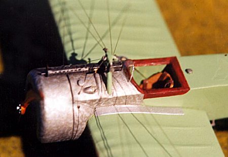
Once the color was acquired, I airbrushed the exterior and brushed the interior aft of the metal covering in addition to the cabane strut. Once this dried, I masked the exterior and painted the metal surfaces Pactra Flat Steel .
 When
this had dried, I swirled thinned-out aluminum paint with a #0000 brush in
random patterns all over the steel. This surprisingly produced the burnished
look of the actual aircraft.
When
this had dried, I swirled thinned-out aluminum paint with a #0000 brush in
random patterns all over the steel. This surprisingly produced the burnished
look of the actual aircraft.
The engine was painted Pactra Steel and given a black wash, after which I brushed the crankcase and propeller boss flat aluminum. The propeller was painted with three shades of brown. I started by painting the entire propeller flat tan, then worked in wet washes of medium and dark brown allowing each coat to dry before applying the other. After all was dry, I covered the propeller with Johnson's FUTURE floor wax.
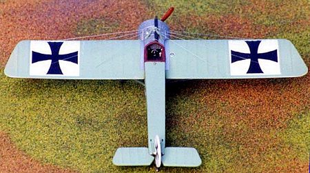
The Iron Cross decals are from SuperScale decal sheet #72-03, the white backgrounds are cut from SuperScale sheet #TF-01, and the ID numbers are made from 8-point dry transfer lettering applied to clear decal film.
The pilot figure is from NEW HOPE DESIGN out of England; if they are still available, they are catalogue- #AIR7213. After cleaning the mold marks and airbrushing the pilot with a metal primer, I hand painted him with various enamels and acrylics, gave him a black wash, and epoxyed two lens to his goggles.
|
REFERENCES |
AIRCRAFT ARCHIVE "AIRCRAFT OF WORLD WAR ONE"-Volume 1, Argus Books, Wolsey Road, Hemel Hampstead, England, 1989.
Apostolo, Giorgio and Begnozzi , Giorgio, COLOR PROFILES OF WORLD WAR 1 COMBAT PLANE , Cresent Books, New York, 1974.
Grosz, P. M., WINDSOCK DATAFILE 15 - FOKKER E III, Albatross Publications, Ltd., Berkhamstead, England, 1989.
WARPLANES AND AIR BATTLES OF WORLD WAR 1, Beekman House, New York, 1973.
Copyright ModelingMadness.com. All rights reserved. No reproduction in part or in whole without express permission from the editor.
If you would like your product reviewed fairly and quickly, please contact the editor or see other details in the Note to Contributors.
Back to Reviews Page 2022