1/72 Farman Flying Fish
| KIT #: | |
| PRICE: | $ |
| DECALS: | None |
| REVIEWER: | Chris Peachment |
| NOTES: | Scratch-built using 10 and 20 thou plastic card, rod, and strut. |
| HISTORY |
My
search to find the ugliest aircraft of all time took me to the Farman Jabiru,
which I scratch built for this website some months ago.
I then idly began to surf for other
examples of the three Farman brothers' work, and what emerged was the fact that
here was a very great aviation company, who had produced more than 200 different
types of aircraft right from the early pioneering days through to the end of
1941, and is seriously under-represented by kit manufacturers. Off the top of my
head, I can think of only one Farman mainstream kit, and that is the Azur Farman
223, which I would dearly like to make, but stands at an eye-watering £50 here
in the UK. There are a few other kits either in vacform which are rare, or
resin, which I don't like.
 Well, if the mountain won't come to Muhammad,
then scratch building is the only solution.
And so here is one that I don't think any mainstream manufacturer is
going to enrage me by releasing just two weeks after I have completed it.
Well, if the mountain won't come to Muhammad,
then scratch building is the only solution.
And so here is one that I don't think any mainstream manufacturer is
going to enrage me by releasing just two weeks after I have completed it.
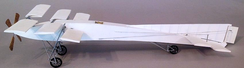
It isn't quite the earliest Farman ever made
but dates from around 1908. While it was built by Farman, it was patented by
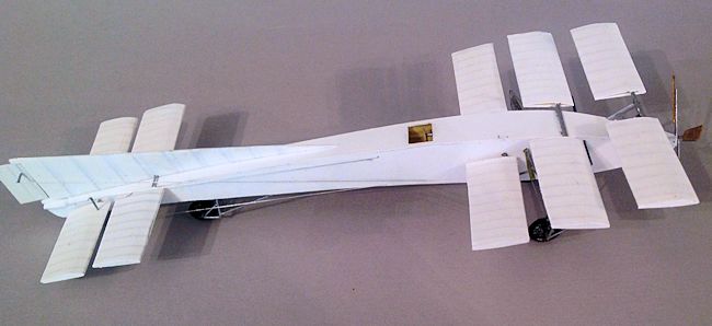
their close colleague Voisin. A glance at the pictures will tell you that it had
3 widely staggered rectangular wings with considerable dihedral, and 2 more in
the rear. And that it follows the highly unusual idea of having wings which are
shorter than the fuselage. A few other aircraft followed this pattern, notably
the Wight Quadruplane, but none of them were successful
The long fuselage was rectangular in section and arched. The nose was pointed
with the inline 4 cylinder Renault engine set inside the fuselage, complete with
a crank handle facing the pilot. The purpose of the
 layout was to have less
resistance from bracing wires. Photos at the factory suggest that at least three
were made, and possibly six. Later in life one was rebuilt with 2 sets of wings
and a new tail. It was then sold to a German Lieutenant Fritsche, and after that
is lost to history.
layout was to have less
resistance from bracing wires. Photos at the factory suggest that at least three
were made, and possibly six. Later in life one was rebuilt with 2 sets of wings
and a new tail. It was then sold to a German Lieutenant Fritsche, and after that
is lost to history.
What isn't apparent from a first glance is that the fuselage, described at the time as banana shaped, does in fact follow the aerofoil section of wings of that period. This would suggest that Farman was onto the idea of a lifting body. Indeed this may well be the first aircraft to explore notion.
| CONSTRUCTION |
The wings are easy enough, and best done in
pairs sharing a common spar. Mount the spar on the lower wing, then curve the
upper wing around it, after having marked the inside ribs with a biro and steel
rule. T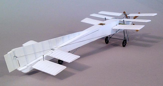 he fin and rudder are made of two pieces of thin card, with the ribs
marked on the inside, then sandwiched together, so that the ribs show through.
Everything got blasted with white at this stage.
he fin and rudder are made of two pieces of thin card, with the ribs
marked on the inside, then sandwiched together, so that the ribs show through.
Everything got blasted with white at this stage.
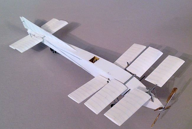
Then
the wings were mounted. As far as I can tell, the forward pair of wings, and
possible more, were able to be rotated about their spar.
What Farman hoped to achieve with this early attempt at variable camber
is anybody's guess. But the few photos definitely show them to be sitting at
varying angles of incidence. And even with differing amounts of dihedral. One
can only shrug and mutter “God help the poor bemused pilot.” But it does relieve
you of worrying too much about symmetry and alignment. If they look a little at
odds with each other, well, that is all there in the pictures. The
forward pair of wings sit on a mount of struts. The rest either sit on top of
the fuselage, or in holes drilled though the sides.
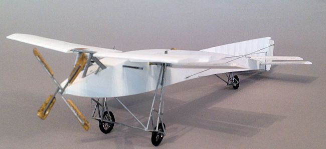
Now comes the fiddly stuff. The plans show
the undercarriage positioned between the second and third wings. There is one
photo that shows it aft of the forward wing and I did dry fit that layout, but
it just didn't look right, so I went with what is shown on the plans. There is
an old engineers' piece of wisdom which goes: when it looks right, it is right.
Hence the 1955 Maserati 250F. Wh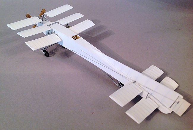 ich looks a lot more right than any of last
year's Grand Prix cars.
ich looks a lot more right than any of last
year's Grand Prix cars.
The undercarriage was made of plastic rod to
the shape you see in the pictures. When I say made, I mean several evenings of
cutting rod to length, marrying it up, then dismantling again when found to be
too short or too long. The wheels are Eduard
photo-etched WWI spokes, which come in varying sizes on the same sheet. The tail
wheel is the smallest size, the main wheels the biggest.
I have discovered a handy new way to make
tyres, which is old fashioned solder, from you local hardware store. It comes in
varying thickness, is very pliable and can be wrapped round a pencil or paint
brush of right diameter, cut with an old blunt blade and the join sealed with
superglue. It is an excellent discovery because it saves using up my dwindling
supply of wheels in the Big Bag of Wheels in the spares box. It also saves
having to file out the wheel centres, a chore which will save your finger tips
being stored in ice and rushed to the casualty department of your local
hospital.
After that it is all over bar the shouting.
Holes were drilled in the rudder and rear wings to take some plain rod as
control horns. These were then rigged to near the cockpit on positions carefully
plotted by looking
 at the photos and then, when nothing could seen at all about
where they emerged, it was done by pure speculation.
at the photos and then, when nothing could seen at all about
where they emerged, it was done by pure speculation.
As you can see the propeller is a four blade
fan which are simply flat paddles mounted at an angle on steel rods. Note that
each rod is mounted to a square spinner plate asymmetrically. Rather than joining
at the centre, the rods form a square around the centre. I imagine this might
have set up a vibration which could have shivered the whole nose to fragments,
but once again, history has shrouded the whole enterprise with a decorous veil.
And that is it. No decals, no windscreen, no
masking, one colour and hardly any rigging.
| CONCLUSIONS |
| REFERENCES |
August 2014
If you would like your product reviewed fairly and fairly quickly, please contact the editor or see other details in the Note to Contributors.