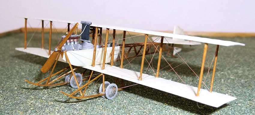
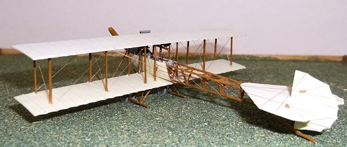
1/72 1911 Avro Type D Biplane
| KIT #: | |
| PRICE: | |
| DECALS: | None required |
| REVIEWER: | Stephen Foster |
| NOTES: |
Scratch built using card, rod, Evergreen strip, wire, paper clip. |
| HISTORY |
In 1911 the aircraft designer and
manufacturer A. V. Roe abandoned his earlier triplane design and instead started
to build a biplane, the first of which flew for the first time on 1 April of
that year. This was a two seat aircraft with a 35hp Green engine and a
triangular tail, but the latter was quickly replaced with a square unit. The
remainder of the machine was built following the same techniques as the earlier
 triplanes
with a triangular shaped fuselage with only the front covered in fabric, and the
radiator mounted in front of the pilot and obscuring his view rather badly. Wing
warping was used to control the aircraft which was relatively stable and easy to
fly. The first of these aircraft took part in the Brooklands - Shoreham air race
of 6 May 1911. In June naval Commander Schwann bought it and had it transported
to Barrow-in-Furness where he had the wheels removed and the skids mounted on
floats. Following a series of trials on different designs of floats the aircraft
unexpectedly lifted off the water to make the first take off from sea-water of
any aircraft in Britain. Five other machines were built in late 1911 and early
1912 with small variations in the basic design, including sesquiplane wings,
different engines and repositioning of the radiator to improve the view of the
pilot. The sixth was a single seater. It is not known exactly how many type D
biplanes were built at A. V. Roe's works at Manchester, but the second and two
others were used in 1913 at the Avro Flying School at Shoreham. The records
indicate that these were scrapped in early 1914.
triplanes
with a triangular shaped fuselage with only the front covered in fabric, and the
radiator mounted in front of the pilot and obscuring his view rather badly. Wing
warping was used to control the aircraft which was relatively stable and easy to
fly. The first of these aircraft took part in the Brooklands - Shoreham air race
of 6 May 1911. In June naval Commander Schwann bought it and had it transported
to Barrow-in-Furness where he had the wheels removed and the skids mounted on
floats. Following a series of trials on different designs of floats the aircraft
unexpectedly lifted off the water to make the first take off from sea-water of
any aircraft in Britain. Five other machines were built in late 1911 and early
1912 with small variations in the basic design, including sesquiplane wings,
different engines and repositioning of the radiator to improve the view of the
pilot. The sixth was a single seater. It is not known exactly how many type D
biplanes were built at A. V. Roe's works at Manchester, but the second and two
others were used in 1913 at the Avro Flying School at Shoreham. The records
indicate that these were scrapped in early 1914.
| THE KIT |
 In the late
1960's Inpact produced a 1/48 scale model of the first machine with the square
tail as part of their Magnificent
Men in Their Flying Machines
series. I well remember building all of these kits at the time, and the Avro
biplane was undoubtedly my favourite. Since then the kit has been re-released
under different manufacturer's labels and it can still be found occasionally,
currently under the Lindberg label. However nobody seems to have bothered to
make one in the Gentleman's scale so I thought that I would fill this gap from
the period of pioneering aviation and scratch build one using the original
Inpact instruction sheet, many photographs and some drawings found on the
internet as guides. The variations in the different machines made research a
little difficult at first, but I found a good photograph of Roe standing beside
the number one machine which I was able to use for my main source of
information. The procedure followed standard scratch build methods using card,
rod, stretched sprue, Evergreen strip, clear acetate and rolled copper wire for
the rigging. Nothing was taken from the spares box.
In the late
1960's Inpact produced a 1/48 scale model of the first machine with the square
tail as part of their Magnificent
Men in Their Flying Machines
series. I well remember building all of these kits at the time, and the Avro
biplane was undoubtedly my favourite. Since then the kit has been re-released
under different manufacturer's labels and it can still be found occasionally,
currently under the Lindberg label. However nobody seems to have bothered to
make one in the Gentleman's scale so I thought that I would fill this gap from
the period of pioneering aviation and scratch build one using the original
Inpact instruction sheet, many photographs and some drawings found on the
internet as guides. The variations in the different machines made research a
little difficult at first, but I found a good photograph of Roe standing beside
the number one machine which I was able to use for my main source of
information. The procedure followed standard scratch build methods using card,
rod, stretched sprue, Evergreen strip, clear acetate and rolled copper wire for
the rigging. Nothing was taken from the spares box.
| CONSTRUCTION |
I started
by carving a small piece of balsa wood to make a male mould for the forward
fuselage which was fabric covered. The two halves were then moulded as described
for other articles. When the halves had been cut and sanded I made up the frame
for the upper fuselage from 20 x 30 thou Evergreen strip. Th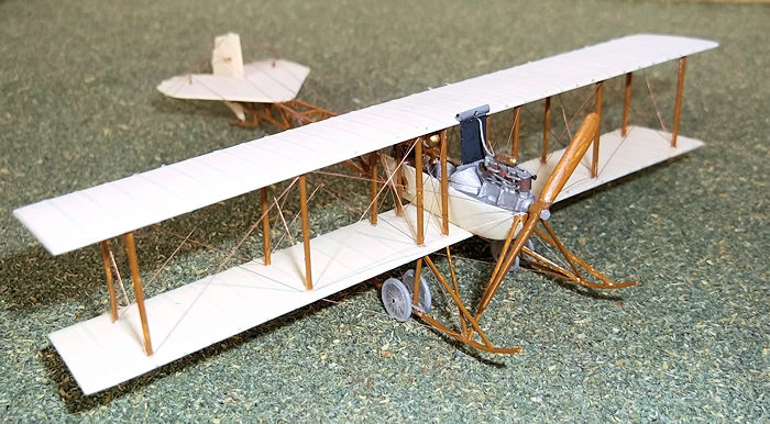 ese
were long enough to go over the top edges of the front fuselage and were glued
into place before I cemented a piece of 10 thou card over the top to represent
the fuselage upper decking. When all of this was dry I cut out the cockpit
openings and the hole where the engine would be fitted later in the nose. The
lower fuselage longeron was glued at the front end to the bottom of the V of the
forward fuselage and two vertical formers glued halfway along the rear of the
fuselage to hold everything in place. When this was dry the remainder of the
fuselage formers were added carefully, this being a fragile structure until all
of the pieces are in place. A cockpit floor was added from 10 thou card, two
seats also from card, and a control column and wheel from rod and stretched
sprue, and a rudder bar in the rear cockpit. I also added some formers to the
sides of the cockpit opening. All of the cockpit interior was painted as I went
along with clear doped linen for the interior sides and wood for the formers and
floor. The seats were aluminium and the controls grey.
ese
were long enough to go over the top edges of the front fuselage and were glued
into place before I cemented a piece of 10 thou card over the top to represent
the fuselage upper decking. When all of this was dry I cut out the cockpit
openings and the hole where the engine would be fitted later in the nose. The
lower fuselage longeron was glued at the front end to the bottom of the V of the
forward fuselage and two vertical formers glued halfway along the rear of the
fuselage to hold everything in place. When this was dry the remainder of the
fuselage formers were added carefully, this being a fragile structure until all
of the pieces are in place. A cockpit floor was added from 10 thou card, two
seats also from card, and a control column and wheel from rod and stretched
sprue, and a rudder bar in the rear cockpit. I also added some formers to the
sides of the cockpit opening. All of the cockpit interior was painted as I went
along with clear doped linen for the interior sides and wood for the formers and
floor. The seats were aluminium and the controls grey.
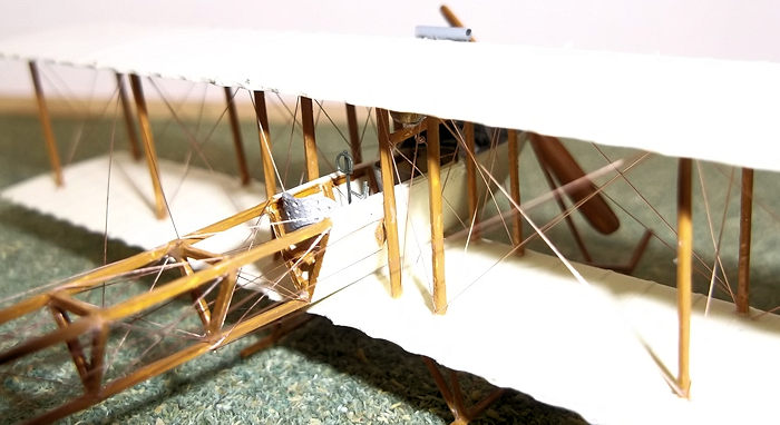
The engine was made from laminated card for the engine block, thin sprue for the cylinders and the rest of the detail was from thin stretched sprue and thin card. I used a photo of the Green Engine in the Science museum in London, contemporary photos and the drawing on the Inpact instruction sheet as guides. The radiator was scribed 20 thou card and the pipes were stretched sprue. The round coaming at the front of the cockpit was made by bending carefully a piece of 15 thou card and cutting it to shape before cementing in place.
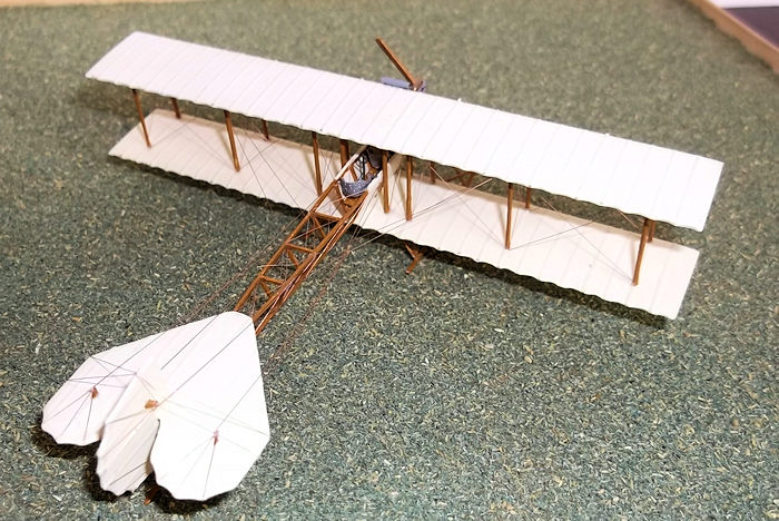
 The wings
and other flying surfaces were cut from 20 thou card. The wings were gently bent
in hot water to get some of the curvature before I added thin strips of Jammy
Dog tape for ribs. These were coated in three coats of varnish and then very
gently rubbed down with worn fine glass paper. The wings on the first machine
had no dihedral but later examples had a very small amount outboard of the
second pair of struts from the fuselage - about 1 to 2 degrees. The tail
surfaces had ribs added as described. Holes were drilled in the wings for the
struts and wing skids before I shaped struts from lengths of 20 x 30 thou
Evergreen strip. I drilled a hole in the lower wing where the fuselage would sit
on it and I also drilled a hole under the fuselage where it made contact with
the wing and then inserted a very short piece of plastic rod to make a pin. I
then painted the wings and other flying surfaces clear doped linen and the
struts brown. A fuel tank was made from scrap sprue and painted brass.
The wings
and other flying surfaces were cut from 20 thou card. The wings were gently bent
in hot water to get some of the curvature before I added thin strips of Jammy
Dog tape for ribs. These were coated in three coats of varnish and then very
gently rubbed down with worn fine glass paper. The wings on the first machine
had no dihedral but later examples had a very small amount outboard of the
second pair of struts from the fuselage - about 1 to 2 degrees. The tail
surfaces had ribs added as described. Holes were drilled in the wings for the
struts and wing skids before I shaped struts from lengths of 20 x 30 thou
Evergreen strip. I drilled a hole in the lower wing where the fuselage would sit
on it and I also drilled a hole under the fuselage where it made contact with
the wing and then inserted a very short piece of plastic rod to make a pin. I
then painted the wings and other flying surfaces clear doped linen and the
struts brown. A fuel tank was made from scrap sprue and painted brass.
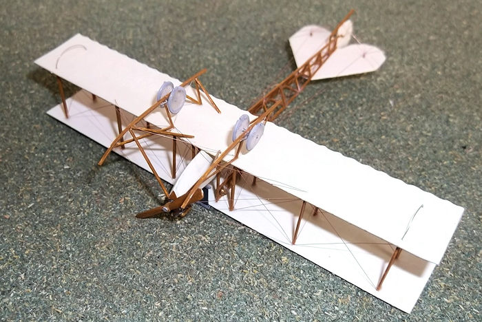
When the wings and struts were complete I cemented the pin on the fuselage into the lower wing and the 4 struts on each side of the fuselage. The rear of the fuselage was supported while this sub-assembly dried. Care must be taken at this stage to get the fuselage and strut alignment correct otherwise the model will not be true. This took me three attempts to get right because on two occasions I failed to get the fuselage lined up properly. I eventually managed this and found it to be the most difficult part of the build. When the structure is aligned and dried out add the four outermost struts to the lower wing and while these are still mobile drop the top wing on to the 8 struts. Do this by putting a small drop of cement into the holes under the upper wing and carefully lowering the wing onto the struts. Finally secure all the struts with liquid cement and allow the whole structure to dry thoroughly. The fuel tank and horizontal bars can now be added to the inner starboard (right) pair of struts. When this is dry add the last of the struts, starting with the inner pairs and work outwards. Now the horizontal tail surface can be cemented into place and the engine and radiator added to the front.
 The
undercarriage skids and legs were cut from 20 x 30 thou Evergreen strip. The
skids were shaped by pinning them to a block of wood and immersing them in
boiling water for 10 seconds and then plunging into cold water also for 10
seconds. Holes were drilled where the struts would be attached later. The front
pair of struts which extend from the nose and the rear vertical pair to the wing
were measured from the plan and cemented into place on one side only to hold one
skid. When this had set sufficiently the other struts struts could be accurately
measured from the model using a pair of dividers, cut and shaped and glued into
place. The process was then repeated for the other side. Axle supports and
radius rods were made from card and thin rod and the axles came from pieces cut
from a paper clip. The undercarriage struts were painted at this stage. The
wheels were made by cutting discs from 20 thou clear acetate sheet for the
centres: these were scribed with the point of dividers to represent the spokes,
and the lengths of 20 thou rod were wound tightly around a paintbrush handle.
This made a series of loops which could be cut to size and put around the discs
to represent the tyres. I held the tyres on the inner wheels with super-glue,
and after drilling out the centres of the wheels these were superglued on to the
axles. The tyres were painted light grey. A tail skid was made from 20 x 30 thou
Evergreen strip and attached to the rudder, and the wing skids were made from 5
amp fuse wire. The propellor blades were shaped from 60 thou card and glued to a
small piece of cocktail stick which made the central boss. The model was
finished by rigging with rolled copper wire.
The
undercarriage skids and legs were cut from 20 x 30 thou Evergreen strip. The
skids were shaped by pinning them to a block of wood and immersing them in
boiling water for 10 seconds and then plunging into cold water also for 10
seconds. Holes were drilled where the struts would be attached later. The front
pair of struts which extend from the nose and the rear vertical pair to the wing
were measured from the plan and cemented into place on one side only to hold one
skid. When this had set sufficiently the other struts struts could be accurately
measured from the model using a pair of dividers, cut and shaped and glued into
place. The process was then repeated for the other side. Axle supports and
radius rods were made from card and thin rod and the axles came from pieces cut
from a paper clip. The undercarriage struts were painted at this stage. The
wheels were made by cutting discs from 20 thou clear acetate sheet for the
centres: these were scribed with the point of dividers to represent the spokes,
and the lengths of 20 thou rod were wound tightly around a paintbrush handle.
This made a series of loops which could be cut to size and put around the discs
to represent the tyres. I held the tyres on the inner wheels with super-glue,
and after drilling out the centres of the wheels these were superglued on to the
axles. The tyres were painted light grey. A tail skid was made from 20 x 30 thou
Evergreen strip and attached to the rudder, and the wing skids were made from 5
amp fuse wire. The propellor blades were shaped from 60 thou card and glued to a
small piece of cocktail stick which made the central boss. The model was
finished by rigging with rolled copper wire.
| CONCLUSIONS |
Since I have returned to modelling I have tended to move away from constructing kits and instead have largely converted models. More recently I have started to scratch build my models as this gives me the total freedom to build what I want to. This was not a difficult build if you have some experience of conversions and/or scratch building biplanes or early monoplane aircraft, and it was only my third attempt at scratch building. I have long wanted this model in 1/72 scale, not least because it takes me down memory lane and reminds me of the Inpact kit of my youth, but it is also an interesting aircraft in its own right, being a forerunner of the more famous Avro 504 series of machines.
| REFERENCES |
If you would like your product reviewed fairly and fairly quickly, please contact the editor or see other details in the Note to Contributors.