| KIT #: | A06007 |
| PRICE: | £18.99 |
| DECALS: | Two options |
| REVIEWER: | Stephen Foster |
| NOTES: | Re-issue of old kit |
| HISTORY |
The
Handley Page 0/400 had its origins in an Admiralty requirement for a long range
twin engined bomber which could carry out anti-submarine patrols and raids on
enemy harbours. Initially the design was to be powered by 120 hp Beardmore
engines to which M. F. Seuter, Director of the Air Department at the Admiralty,
retorted to F. Handley Page "Look Mr. Page, what we want is a bloody paralyser -
not a toy!" The first design, which became the 0/100 was rolled out of the
factory in December 1915 and made
 its maiden flight in the middle of that month.
A small number of 0/100's entered service but the development of the Rolls Royce
Eagle VIII engine meant that a redesign of the airframe was possible with a new
fuel system and heavier bomb load - this was to become the 0/400. In April 1917
the 0/400 became operational as a day bomber in France, operating with the
Independent Force and later with the RAF. They operated against industrial
targets in the Frankfurt-Cloogne-Stutgart area and against targets in the Saar
region.
its maiden flight in the middle of that month.
A small number of 0/100's entered service but the development of the Rolls Royce
Eagle VIII engine meant that a redesign of the airframe was possible with a new
fuel system and heavier bomb load - this was to become the 0/400. In April 1917
the 0/400 became operational as a day bomber in France, operating with the
Independent Force and later with the RAF. They operated against industrial
targets in the Frankfurt-Cloogne-Stutgart area and against targets in the Saar
region.
In October 1917 night operations were started and these continued to the end of the war in November 1918, with up to 400 machines in service. In spite of the efforts of the very brave crews who flew these raids, often in poor weather and against increasingly heavy defences, it was accepted that a significant proportion of the bombs dropped would not explode. In October the 1650lb SN bomb was brought into service was so large it had to be carried externally under the bomb bay, (the 0/400 could carry up to 16 112lb bombs in the internal bomb bay); several of these monsters were dropped on Kaiserslauten in the Saarland. A limited number of 0/400 saw service in the Middle East in September 1918. Seven were taken on charge by the US Air Service but none of them were used operationally. After the war ended the Handley Page bombers were retired in favour of the Vickers Vimy, although eight were used for VIP transport until 1920, and few others also continued in civilian use in the early post war years.
| THE KIT |
I have recently started modelling again after a break of over 30 years and after
making a couple of simple kits from the box wanted to take on a challenge and a
kit that I had long wanted to build. It happened that I had an unbuilt 0/400 in
the roof left from my former modelling days, but now Airfix have to re-released
it again. When I looked at the Airfix website I saw that this kit
 requires a
skill level of 3 (which is about two above my current level), so that I knew
this could be a difficult build. It was. If you have not built biplanes before
this is definitely not one to start with. If you have then this kit will provide
you with real challenges but in the end the effort is worth it because there are
so few large biplanes from this era. I remember building this model when it was
first released in the late 1960's and made a mess of it: now I wanted to make a
decent one, but it took a lot of patience and time. Considering its age this kit
stands up well against modern offerings and it is reasonably accurate, but it
will need some attention, especially the mould marks which require cleaning up
before you start. This is a big kit - both in the number of parts (over 160),
many of them quite small, and its size, so you need to take care when building
that you do not lose any. The plastic is dark green and in my old kit was good
quality. You will need to remove the over-heavy rib detail from the flying
surfaces, and I suggest that at each stage you carry out a dry run to check the
fit of parts, and where necessary file or trim to improve them. There is not too
much of this but it is still worth checking first. I give detailed instructions
here to make some small improvements to the model: how far you decide to go is
of course entirely up to you and your level of skill and comfort with fiddly
work. Two sets of markings are provided,
one for 207 Squadron, late 1918 night finish, and one for 1917 day scheme. On
mine the register was very poor so I discarded them all except for the "lift
here" signs.
requires a
skill level of 3 (which is about two above my current level), so that I knew
this could be a difficult build. It was. If you have not built biplanes before
this is definitely not one to start with. If you have then this kit will provide
you with real challenges but in the end the effort is worth it because there are
so few large biplanes from this era. I remember building this model when it was
first released in the late 1960's and made a mess of it: now I wanted to make a
decent one, but it took a lot of patience and time. Considering its age this kit
stands up well against modern offerings and it is reasonably accurate, but it
will need some attention, especially the mould marks which require cleaning up
before you start. This is a big kit - both in the number of parts (over 160),
many of them quite small, and its size, so you need to take care when building
that you do not lose any. The plastic is dark green and in my old kit was good
quality. You will need to remove the over-heavy rib detail from the flying
surfaces, and I suggest that at each stage you carry out a dry run to check the
fit of parts, and where necessary file or trim to improve them. There is not too
much of this but it is still worth checking first. I give detailed instructions
here to make some small improvements to the model: how far you decide to go is
of course entirely up to you and your level of skill and comfort with fiddly
work. Two sets of markings are provided,
one for 207 Squadron, late 1918 night finish, and one for 1917 day scheme. On
mine the register was very poor so I discarded them all except for the "lift
here" signs.
| CONSTRUCTION |
I did not start by assembling the wings as per the instructions as I knew that
this could cause problems with the wings later and I wanted to try to avoid
these by using a different assembly sequence. I started with the fuselage and
after cleaning the mould marks cemented strips of plastic card to the sides to
represent the missing framing in the cockpit areas. I replaced the small door
between the pilot's and front gunner's cockpits, and added a small piece of card
on the floor below the pilots' seat to represent a
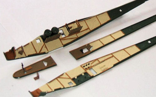 door there. You will also
need a seat for the navigator/gunner next to the pilot (it folded up to the port
(left) fuselage side), a rudder bar, a small instrument panel in the front
cockpit, seat belts, other controls as desired and ammunition holders for Lewis
gun drums in the rear cockpit: these were small pieces of thin card and were
glued to the fuselage sides when ready: use the mouldings in the kit as a guide
for the size and shape of the drum holders. Cut a triangular aperture in the
rear fuselage floor (part 63) just aft of the gunner's hatch and insert a small
piece of clear acetate to represent the window. I painted the interior clear
doped linen, light brown for the wood frames and dark wood for the slatted
floors and gunner's hatch cover (part 64). The fuel tanks cannot be seen but
need to be put in as they help to keep the fuselage square - I painted them
black. Replace all the window transparencies with clear acetate sheet. Before
you put the tail unit together you will need to sand down the over heavy rib
detail: do this now while you are waiting for paint or sub-assemblies to dry.
door there. You will also
need a seat for the navigator/gunner next to the pilot (it folded up to the port
(left) fuselage side), a rudder bar, a small instrument panel in the front
cockpit, seat belts, other controls as desired and ammunition holders for Lewis
gun drums in the rear cockpit: these were small pieces of thin card and were
glued to the fuselage sides when ready: use the mouldings in the kit as a guide
for the size and shape of the drum holders. Cut a triangular aperture in the
rear fuselage floor (part 63) just aft of the gunner's hatch and insert a small
piece of clear acetate to represent the window. I painted the interior clear
doped linen, light brown for the wood frames and dark wood for the slatted
floors and gunner's hatch cover (part 64). The fuel tanks cannot be seen but
need to be put in as they help to keep the fuselage square - I painted them
black. Replace all the window transparencies with clear acetate sheet. Before
you put the tail unit together you will need to sand down the over heavy rib
detail: do this now while you are waiting for paint or sub-assemblies to dry.
When you are satisfied with the interior detail assemble the front and rear
cockpit parts, adding small items such as the wires on the rear gunner's seat,
etc. Then glue the fuel tanks, cockpit floors, bomb rack (with bombs if
required), on to one fuselage s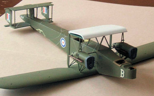 ide and cement the other side and rear fuselage
bottom plate (part 63), making sure that all is square. Leave to dry out
thoroughly. Fix the top of the rear and front fuselage, tail unit and wing stub
ensuring that the two latter parts are correctly aligned: this is very important
as it affects the wings and tail unit later. Leave the whole to dry out properly
and then fill any gaps and holes. On my kit one of the fuselage sides had
distorted a little so I had to use some weight to hold things in shape while it
dried out - it worked. Add the protection around the pilot's cockpit but do not
put on the fuselage rails or generators at this stage. The holes for the struts
of the tail unit in the rear fuselage are in the wrong place - they will not
line up as required so fill them and drill new ones so that they line up with
the holes in the horizontal tail unit. The tab on the centre fin (part 72) is
also too long and needs to have the front end cut off so that the fin leading
edge is about 0.5mm ahead of the front struts. The lugs on the fin also need
shortening so that there is a tiny gap (about 1mm) between the fin and the upper
horizontal tail surface. The kit rudders are too small so I cut new ones from 20
thou plastic card. I now glued the central fin and tail skid support (part 151)
to the fuselage and filled the gaps.
ide and cement the other side and rear fuselage
bottom plate (part 63), making sure that all is square. Leave to dry out
thoroughly. Fix the top of the rear and front fuselage, tail unit and wing stub
ensuring that the two latter parts are correctly aligned: this is very important
as it affects the wings and tail unit later. Leave the whole to dry out properly
and then fill any gaps and holes. On my kit one of the fuselage sides had
distorted a little so I had to use some weight to hold things in shape while it
dried out - it worked. Add the protection around the pilot's cockpit but do not
put on the fuselage rails or generators at this stage. The holes for the struts
of the tail unit in the rear fuselage are in the wrong place - they will not
line up as required so fill them and drill new ones so that they line up with
the holes in the horizontal tail unit. The tab on the centre fin (part 72) is
also too long and needs to have the front end cut off so that the fin leading
edge is about 0.5mm ahead of the front struts. The lugs on the fin also need
shortening so that there is a tiny gap (about 1mm) between the fin and the upper
horizontal tail surface. The kit rudders are too small so I cut new ones from 20
thou plastic card. I now glued the central fin and tail skid support (part 151)
to the fuselage and filled the gaps.
| COLORS & MARKINGS |
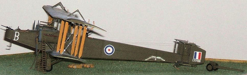
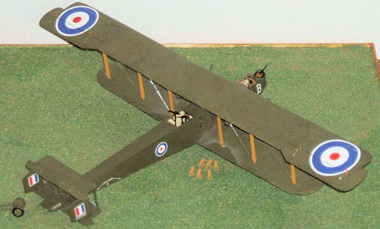
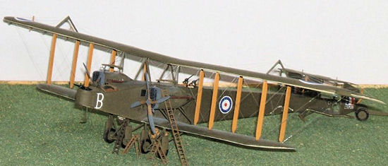
My model represents an RNAS machine from early 1918 in day finish with PC10 upper surfaces and clear doped linen undersides, so I decided to paint the fuselage and tail surfaces at this stage. I also had to paint the rudder flashes, fuselage roundels and individual letter on the nose, and I also added the serial (from the spares box) and lift here signs (from the kit), as they are much easier to apply now rather than later. I will explain later how to paint roundels if you do not want to use those provided in the kit.
| MORE CONSTRUCTION |
Drill the holes for the tail rigging: on the original machines these were double
wires throughout and ran across the tail unit between the forward struts, rear
struts and rudders and the fuselage struts where they passed through the fin.
They also ran fore-aft between the fuselage struts. The box art is of some help
but also look at drawings if you can: the Datafile no 116 on the 0/400 has
excellent sketches which are very clear. Single wires ran from left to right
across the front struts, between the leading edges
 of the rudders through the
fin and from the centres of the rudders via the rear of the fin. In all quite a
birdcage - if you do not have access to the drawings or do not feel up to the
challenge just put in the bracing between the struts and rudders. When you have
drilled the holes you need to assemble the tail unit. Glue the fuselage struts
first, then the two on the lower tail surface and while these are still moveable
carefully lower the upper tail surface and glue into place. Allow this assembly
to dry out thoroughly. If you have cut new rudders add these when the assembly
has dried out: if you use those from the kit you will have to glue them in place
before putting on the upper tail unit. When the tail is dry add the rigging.
This is a time consuming process but is best done now as there is little else of
the kit to get in the way or be damaged. Remember if you decide to rig as per
the original aeroplane you are taking on the equivalent of a small biplane! Make
the elevator horns but do not put them on yet, nor the control wires to the tail
as all of these will be added later.
of the rudders through the
fin and from the centres of the rudders via the rear of the fin. In all quite a
birdcage - if you do not have access to the drawings or do not feel up to the
challenge just put in the bracing between the struts and rudders. When you have
drilled the holes you need to assemble the tail unit. Glue the fuselage struts
first, then the two on the lower tail surface and while these are still moveable
carefully lower the upper tail surface and glue into place. Allow this assembly
to dry out thoroughly. If you have cut new rudders add these when the assembly
has dried out: if you use those from the kit you will have to glue them in place
before putting on the upper tail unit. When the tail is dry add the rigging.
This is a time consuming process but is best done now as there is little else of
the kit to get in the way or be damaged. Remember if you decide to rig as per
the original aeroplane you are taking on the equivalent of a small biplane! Make
the elevator horns but do not put them on yet, nor the control wires to the tail
as all of these will be added later.
I rigged this model with invisible thread because it is large and easy to drill all of the necessary holes in addition to the ones already in the kit. I discovered why it is called invisible thread on many occasions: trying to find ends or dropped pieces was very frustrating at times - next time I will use grey thread as it is easier to see and has approximately the right colour. It will also mean fewer grey hairs for me. I attached the thread at one end by glueing it down with superglue and then reinforced it by cementing the end with plastic cement and a small piece of scrap plastic if the end was concealed, as in the wings. This was probably overkill but I did not want any pieces breaking free when pulled threads taut - it certainly worked.
The wing ribs are too heavy and need rubbing down: this can also be done while
work on the fuselage is in progress and you are waiting for sub-assemblies or
paint to dry. Airfix conveniently provide holes for rigging in the wings but
there is a problem as they only provide holes for flying and lift wires between
the struts: there are none fore and aft between the struts. Therefore drill the
necessary holes in the upper and lower wing halves for both top and bottom
wings. If you want to put in the double rigging wires these ran outwards from
the fuselage from bottom to top between the all of the struts and the engines.
The bracing wires which stabilised the upper wing overhang were also double. Do
not forget the holes for the aileron control wires which ran above and below the
top wing. If you want to simulate the fabric of the folding sections of the
wings using tissue paper you will need to carefully cut the wedge shaped pieces
from the trailing edges of the wings, making sure that they are symmetrical and
of equal size. After the wings are assembled the tissue paper can be glued into
place and then painted to stretch it. I tried to do this on my model but the
result was awful and I resorted to replacing the cut outs with card and filler.
Unfortunately the paint mix for the
 repair did not match exactly and the repair
area shows a little on the photos. If I were to do this again I would not bother
with this particular detail as it is difficult to get it to look right. When you
are happy with the wings put the rigging wires through the upper halves of the
lower wings (parts 9 and 10). The upper parts of the inner wing units can be
glued to the stubs and fuselage and any gaps filled and rubbed down. Now add the
handrails to the fuselage.
repair did not match exactly and the repair
area shows a little on the photos. If I were to do this again I would not bother
with this particular detail as it is difficult to get it to look right. When you
are happy with the wings put the rigging wires through the upper halves of the
lower wings (parts 9 and 10). The upper parts of the inner wing units can be
glued to the stubs and fuselage and any gaps filled and rubbed down. Now add the
handrails to the fuselage.
Assemble the engines if you have not already done so. I found that the fit of parts was very good but the joints need rubbing down and cleaning up. Paint the interior of the rear (parts 95-98) matt black before assembly. Leave the propellers off as these only get in the way and can easily be added later. Glue the top and bottom engine struts (parts 110, 112, 116, 118,) into place making sure that they are properly aligned and when dry fill the joints which I found to be poor. When the engine assemblies are dry they can be painted as they are difficult to paint when the model is assembled. The nacelles were PC10 or NIVO depending on the aircraft modelled, the radiator fronts black but the sides were dark grey on my model, and the exhausts were painted using a mixture of copper and rust. Finally add the exhausts but do not put on the engine platforms until later.
Now we diverge again from the kit instructions because the fit of the wings is not good and problems can arise with alignment and filling of gaps if you follow their method. First check carefully the alignment of the upper sections of the bottom wings (parts 3 and 13) and file down and adjust as necessary. Glue the upper wing sections to the inner wing stubs making sure that you have the correct dihedral by supporting the wing tips while they dry out. Fill any gaps and sand down making sure that you do not damage the rigging wires on the inner wing sections. Fit the fuselage cabane struts (123 and 124) to the fuselage. If you want to, drill two small holes in the fuselage just in front of the cabane struts and under the centre-section of the top wing for fuel pipes: the pipes ran in front of the forward struts. I now painted the upper surfaces of the bottom wing and the cabane struts. Attach one engine at a time to the lower wings. Do this by glueing the forward bottom strut (109 on the port - left engine), and rear strut (111 on the same engine), to the nacelle and then glue the sub-assembly to the holes n the bottom wing. Now cement the control bar (part 114) and the inner engine strut (113) between the engine nacelle and the fuselage, making sure that the alignments are correct. This may need a little support while it is drying out. If you have been careful in attaching the top and bottom engine struts struts as described above these should give you more rigidity when putting the nacelles into place and make this assembly easier. Only assemble the second engine when the first is completely dry. Now fit the large wing struts (121 and 122) into the holes in the lower wing at the rear of the engine and carefully lower and cement the lower part of the upper wing centre section (125) into place, again taking care with alignment. Leave this assembly to dry completely before rigging or you may pull the alignment out of true. Complete the rigging of the centre section including the engine bays, making sure that the thread is tight but does not distort the wings.
 I now had a problem because the kit is supposed to have 167 parts but mine only
had 166 - part number 126, the upper wing centre section, was missing! I moulded
a new one from plastic card and added strips of card to the leading and trailing
edges of part 125. In any event do not glue part 126 in place yet because there
is work to do on alignments first. Hold one of the upper wing bottom pieces
(part 6 or 16) to the edge of the top wing centre-section and test the fit of
the main wing struts. This is fiddly but by inserting the struts into the
location holes it can be done and the alignment of the wing sections can be
checked. In my case the rear inner strut was too long and needed to be shortened
by a couple of mm or 1/16 inch. The wings are different so make sure that you
measure both wings and sets of struts. When you are happy that the wing joints
will be flush and you have the correct dihedral, glue the wing struts into the
top of one of the lower wings. Place a small drop of cement into the front holes
on the upper wing and place these on on the ends of the forward struts, then
place a small drop of cement on the tops of the rear struts and ease these
forward into the holes on the rear of the wing. Run some glue along the joint
between the two wing sections and bring the sections together. Support this
assembly firmly and allow it to dry overnight, making sure that the struts are
vertical. Repeat this operation on the other wing. Now you can fill and rub down
the joints on the underside of the wings. When you are satisfied with the joints
you can rig the wings as required and put the top sections of the top wings and
bottom sections of the lower wings into place. Do not forget to add the king
posts and rig these on the top wing first. More filling will be needed on the
undersides of both of the wings and probably on the top sides along the centre
section and the undersides of the lower wing too. Make sure that you do not
damage the rigging when sanding down the filler and joins. This may sound a
tricky set of operations and they are, but they will give you good joints and
get around the alignment problem which seems to mar so many attempts with this
model and give a much better result overall. Just take your time and be patient
and careful, and you will reap the rewards of your efforts. I now painted the
top and bottom of the upper wing and the cockades as the kit transfers were
unusable and in any case not suitable for the aircraft depicted in my model.
Painting cockades is not difficult. First scribe on the outer circle of the
cockades with a sharp pair of dividers and then painted the circle in with white
paint. As the white appears in the cockades two coats may be needed to achieve
the correct density. With care, thin paint and a fine brush the paint can be
allowed to run into the groove made by the dividers and a neat outline will
result. When the white paint is dry scribe on circles for the red and blue
colours, again using dividers, and complete the painting as described above.
I now had a problem because the kit is supposed to have 167 parts but mine only
had 166 - part number 126, the upper wing centre section, was missing! I moulded
a new one from plastic card and added strips of card to the leading and trailing
edges of part 125. In any event do not glue part 126 in place yet because there
is work to do on alignments first. Hold one of the upper wing bottom pieces
(part 6 or 16) to the edge of the top wing centre-section and test the fit of
the main wing struts. This is fiddly but by inserting the struts into the
location holes it can be done and the alignment of the wing sections can be
checked. In my case the rear inner strut was too long and needed to be shortened
by a couple of mm or 1/16 inch. The wings are different so make sure that you
measure both wings and sets of struts. When you are happy that the wing joints
will be flush and you have the correct dihedral, glue the wing struts into the
top of one of the lower wings. Place a small drop of cement into the front holes
on the upper wing and place these on on the ends of the forward struts, then
place a small drop of cement on the tops of the rear struts and ease these
forward into the holes on the rear of the wing. Run some glue along the joint
between the two wing sections and bring the sections together. Support this
assembly firmly and allow it to dry overnight, making sure that the struts are
vertical. Repeat this operation on the other wing. Now you can fill and rub down
the joints on the underside of the wings. When you are satisfied with the joints
you can rig the wings as required and put the top sections of the top wings and
bottom sections of the lower wings into place. Do not forget to add the king
posts and rig these on the top wing first. More filling will be needed on the
undersides of both of the wings and probably on the top sides along the centre
section and the undersides of the lower wing too. Make sure that you do not
damage the rigging when sanding down the filler and joins. This may sound a
tricky set of operations and they are, but they will give you good joints and
get around the alignment problem which seems to mar so many attempts with this
model and give a much better result overall. Just take your time and be patient
and careful, and you will reap the rewards of your efforts. I now painted the
top and bottom of the upper wing and the cockades as the kit transfers were
unusable and in any case not suitable for the aircraft depicted in my model.
Painting cockades is not difficult. First scribe on the outer circle of the
cockades with a sharp pair of dividers and then painted the circle in with white
paint. As the white appears in the cockades two coats may be needed to achieve
the correct density. With care, thin paint and a fine brush the paint can be
allowed to run into the groove made by the dividers and a neat outline will
result. When the white paint is dry scribe on circles for the red and blue
colours, again using dividers, and complete the painting as described above.
 The undercarriage is next. First all of the parts will need cleaning of bad
mould joints and the tyres will need similar treatment. Paint the tyre walls
black and the treads dark grey: you could add a little "mud" along the edge of
the treads if you wish. Assembly of the undercarriage is again a little fiddly
but if you have got this far it should not be a problem. Just make sure that
everything is properly aligned while it dries out. Glue the sub-assemblies into
place and allow them to dry thoroughly. Add the wind pumps to the sides of the
fuselage, fuel pipes, engine platforms (and their supporting wires), ailerons
and all of the control surface horns. Complete the rigging by adding all of the
control cables. The trolley can be assembled and painted and final details
added: propellers, pitot tube, crew entry hatch, gun pillars and guns, forward
gun ring, windscreens and the tail skid, etc. The tail skid had two springs, one
on each side, which can be simulated with a ring of stretched sprue. I added a
crew ladder and two maintenance ladders to my model just for effect - they were
made from thin microstrip.
The undercarriage is next. First all of the parts will need cleaning of bad
mould joints and the tyres will need similar treatment. Paint the tyre walls
black and the treads dark grey: you could add a little "mud" along the edge of
the treads if you wish. Assembly of the undercarriage is again a little fiddly
but if you have got this far it should not be a problem. Just make sure that
everything is properly aligned while it dries out. Glue the sub-assemblies into
place and allow them to dry thoroughly. Add the wind pumps to the sides of the
fuselage, fuel pipes, engine platforms (and their supporting wires), ailerons
and all of the control surface horns. Complete the rigging by adding all of the
control cables. The trolley can be assembled and painted and final details
added: propellers, pitot tube, crew entry hatch, gun pillars and guns, forward
gun ring, windscreens and the tail skid, etc. The tail skid had two springs, one
on each side, which can be simulated with a ring of stretched sprue. I added a
crew ladder and two maintenance ladders to my model just for effect - they were
made from thin microstrip.
| CONCLUSIONS |
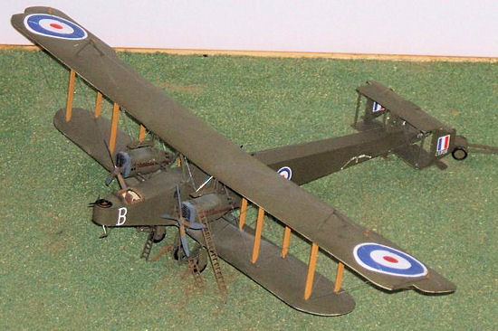
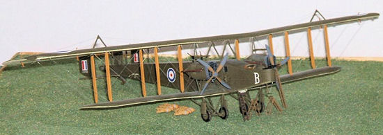
This model is a major undertaking - when I started it I was looking for a challenge and I certainly found it with this one. Large biplanes, and this has a span of nearly 17 inches, are not quick or easy to build but the effort is, in my opinion, well worthwhile. The rigging was not as difficult as some biplanes that I have tackled, except for the tail unit. Overall it could have been easier if I had used single rather than double rigging, but on an aeroplane this size I wanted to be as authentic as possible. Considering how old this kit is I think that Airfix made an excellent job of it - it has stood the test of time well. There is always scope for even more detailing if you really want to, but I was satisfied with the few extras that I added. Overall I enjoyed the challenge that it offered but would only recommend it to the experienced biplane modeller.
| REFERENCES |
Windsock Datafile nos. 116 and 121 Handley Page 0/400.
The British Bomber Since 1914 by P. Lewis.
Blandford Colour Series: Bombers 1914-19, K. Munson.
Stephen Foster
December 2012 If you would like your product reviewed fairly and fairly quickly, please
contact
the editor or see other details in the
Note to
Contributors.