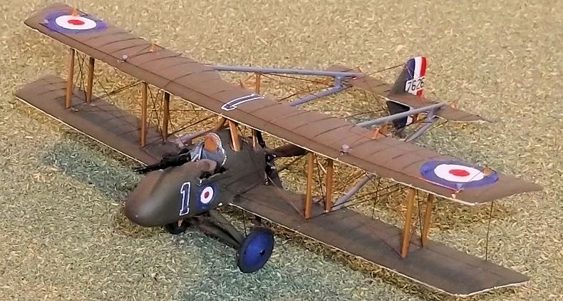
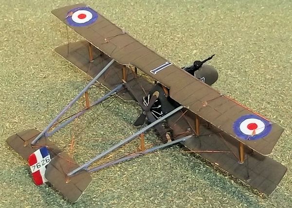
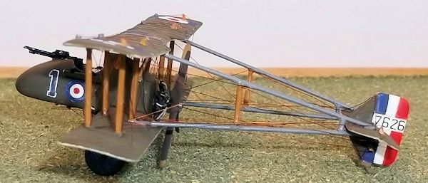
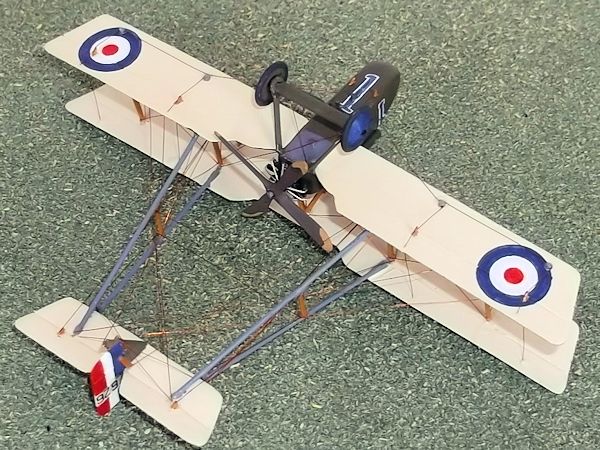
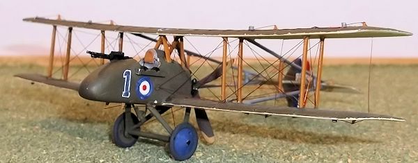
Airfix 1/72 R.A.F. F.E.8 (conversion)
| KIT #: | 1048 |
| PRICE: |
£5.00 |
| DECALS: | One option |
| REVIEWER: | Stephen Foster |
| NOTES: | Conversion using Airfix Avro 504 |
| HISTORY |
The Royal Aircraft
Factory FE 8 was designed in 1915 and first flew in October of that year. It was
an exact contemporary of the de Haviland D H 2 with which it shared several
design characteristics, including the pusher layout armament
of a single Lewis machine gun. The design was unusual in that it employed
the extensive use of steel tubing in its structure and the underside of the
nacelle was armoured. It was powered by a 100 hp Monosoupape rotary engine
driving a four bladed airscrew. The machine had a top speed of 98 mph which was
good for the time. Orders were placed with Vickers in Britain and Darracq in
France but production difficulties meant that there was a delay in service
machines reaching the front line squadrons until the summer of 1916. No 40 and
41 Sqdns were formed at Gosport in February 1916 to take these machines but
delays in deliveries meant that elements of 40 Sqdn were not able to go to
France until August, while 41 Sqdn did not receive FE 8s until September
 and it
did not become operational until October. Nos 5 and 29 Squadrons also operated
with the type but were never fully equipped with it.
and it
did not become operational until October. Nos 5 and 29 Squadrons also operated
with the type but were never fully equipped with it.
The operational history of the FE 8 has been obscured by its later unhappy history, when in fact it was able to contribute to Allied aerial successes in late 1916 and into early 1917: 40 Sqdn reporting 23 victories between the end of September 1916 and the beginning of March 1917 and 40 Sqdn reported 18 victories between January and June 1917. However there is no doubt that the pusher design was obsolete by the beginning of 1917 as the Germans introduced large numbers of Albatross and Halberstadt tractor scouts. However on March 7th von Richtofen was forced to make an emergency landing by having his fuel tank holed by FE 8's from 40 Sqdn., but on March 9 1917 six out of nine FE 8s from the same RFC unit were either shot down or badly damaged by von Richtofen's Jasta 11. The unit started to re-equip with Nieuport 17 scouts a few days later but the pilots of 41 Sqdn had to continue with the type until July 1917 by which time their machines were hopelessly obsolete. A small number were sent to training squadrons in Britain but their service history was limited. A good design that took too long being brought into service, and its use long after it had been superseded because there were no suitable replacements, was a frequent experience for the RFC for much of the First World War. This has contributed greatly to much of the unfair and ill-informed criticism of the Royal Aircraft Factory and its designs, but the fact remains that the FE 8 represented too little too late in the struggle for air supremacy in the mid -War years.
| THE KIT |
There is a kit of the
FE 8 in 1/72 scale currently available on the market but it is in resin and I
consider it to be expensive. In June 1972 A. Woollett published an article in
Airfix Magazine on how to
 convert an Airfix DH 4 to an FE 8 and it was this
article that gave me the idea to attempt a build of my own. However I chose to
use the Airfix Avro 504 as the starting point as I have a ready supply of these
and I would otherwise need a rotary engine from the spares box. I would still
need a four bladed propellor and Lewis machine gun however so it does not make a
great deal of difference which model you choose as both are the same price.
convert an Airfix DH 4 to an FE 8 and it was this
article that gave me the idea to attempt a build of my own. However I chose to
use the Airfix Avro 504 as the starting point as I have a ready supply of these
and I would otherwise need a rotary engine from the spares box. I would still
need a four bladed propellor and Lewis machine gun however so it does not make a
great deal of difference which model you choose as both are the same price.
| CONSTRUCTION |
I started by moulding
the fuselage from plastic card using the push mould technique which I have
described in the Vickers Gunbus conversions and on Airfix Tribute Forum/Modelling
tips and techniques. Do not try to mould the fairing behind the pilot's head as
this will be added later. When you have two halves of the nacelle cut them out
and sand the edges to achieve a good fit before cutting out the cockpit
aperture. Make a floor from card and add fuselage stringers from thin rod, a
control column, rudder bar, seat, and any other details you wish. I cut a piece
of 30 thou card and glued this on one side of the rear of the nacelle so that a
firm support is present to hold the engine later. When you have painted the
cockpit interior (which should be aluminium sides and floor), and are happy with
the cockpit
 sub-assembly you can glue everything together and leave to dry out.
The nacelle joints may need a little filler and rubbing down.
sub-assembly you can glue everything together and leave to dry out.
The nacelle joints may need a little filler and rubbing down.
The pilot's headrest
was made from a cut down DH 4 fuel tank which I had spare, but it could also be
built up from scrap card and filler. If you use the fuel tank you will need to
add a small piece of card to blank the open end behind the pilot's head: at the
same time add another smaller piece of card to represent the headrest. Cut two
ammunition boxes from 10 thou card and cement these either side of the cockpit
and cut four half discs to represent spare drums of ammunition. Drill out a hole
for the pin on the engine at the rear of the nacelle, and four holes under the
nacelle for the undercarriage legs. You will need a small piece of shaped card
for the air intake under the rear fuselage, a piece of rod for the compass
fairing under the cockpit and a generator and supports which also sit under the
cockpit (on some machines only - check photos if you are not sure). Leave the
generator off for the time being. Finally cut four small holes on the top of the
nacelle for the cabane struts. I used the engine from the 504 and added push
rods to the front of the cylinders from thin stretched sprue. The propellor was
a spare from a DH 4: the blades were reduced in size to the correct diameter and
the locating pin cut off. Then I drilled a hole through the centre of the
propellor and pushed the locating pin back in from the front so that a tiny
piece protruded from the rear to represent the new boss. When the engine and
propellor are painted they can be cemented together and set aside.
The wings are next. Measure
the scale span of the FE 8 carefully and mark this on to the top wing of the
Avro 504. Cut off the wing tips but leave them square for the moment. Now reduce
the chord of the wings by cutting off both the leading and trailing edges: I
laid the wings on a plan of the FE8 wings and used the aileron grooves as a
datum line to measure from. When the wing chord is correct shape the new tips
and then restore the aerofoil section of the wing by carefully filing and
sanding the leading and trailing edges. Now cut out the rear of the centre
section to the new shape and sand that down and score in the new aileron
grooves. Carefully bend the wing flat by using gentle but firm pressure with
your fingers, before bending the wings again so that the correct dihedral is
given to the outer wing panels. There is no need to score the wings to do this -
I found that gentle repeated bending was enough as the plastic is just soft
enough to take on the new shape.
The lower wing should have
the centre section removed first and then work on each half separately. Start by
reducing the chord of one wing half in the same way as the upper wing, and then
cut the new tip shape. File and sand the tip and aerofoil section of the whole
wing half: note it will be too long at this stage but it can be reduced to the
correct length later. Lay the nacelle on to the inner end of the wing and lay
the wing and nacelle on to the plan of the aircraft so that you can measure
where the wing will
 join the fuselage. Mark the wing carefully and check again
that you have the exact size needed to fit the plan. Now cut the inner section
of the wing to fit the fuselage nacelle. Finally cut out the rear of the wing to
match the shape of the trailing edge of the upper wing, sand and file the
aerofoil section and score the new aileron grooves. Repeat this set of
procedures for the opposite wing. When the lower wings are ready bend them
gently as already described to get the correct dihedral, then they can be glued
to the nacelle: support them while they dry out. Fill any gaps and rub down.
Mark accurately where the strut holes need to be on the top surface of the lower
wing and the under-surface of the top wing and drill small holes.
join the fuselage. Mark the wing carefully and check again
that you have the exact size needed to fit the plan. Now cut the inner section
of the wing to fit the fuselage nacelle. Finally cut out the rear of the wing to
match the shape of the trailing edge of the upper wing, sand and file the
aerofoil section and score the new aileron grooves. Repeat this set of
procedures for the opposite wing. When the lower wings are ready bend them
gently as already described to get the correct dihedral, then they can be glued
to the nacelle: support them while they dry out. Fill any gaps and rub down.
Mark accurately where the strut holes need to be on the top surface of the lower
wing and the under-surface of the top wing and drill small holes.
The tail unit was made
from 20thou card shaped to aerofoil section with the elevators and rudder scored
in. The booms were made from florists wire as this was of the correct diameter
and could be obtained at little cost from a local shop! It was much cheaper than
brass wire and is rigid enough to provide a stronger model than if plastic rod
were used. Having carefully measured and cut the boom wires I then cut small
indents into the top of the lower wings and bottom of the top wing. Lay the
wings on the plan and lay the boom wires so that are aligned with the plan and
the ends are on the wing surface. Mark careful with a pencil where the booms
need to be attached and then use the end of a needle file to grind out a small
indent. I find that slowly but carefully twisting the file between my fingers is
enough to gouge out the groove of the required size: these should be deeper
forward and very shallow at the rear as the angle of the boom to the wing is
quite high - check the plans. Whether you attach the booms to the wings now or
wait until you have assembled the top wing to the lower is up to you. If you use
plastic rod it may be easier to wait, but because I used wire and epoxy glue I
had to attach mine at this stage, which meant that getting the angle right would
be a challenge. I solved the problem as follows. The horizontal distance between
the trailing edge of the wing and the leading edge of the horizontal tail unit
is 44mm. The vertical distance between a line drawn horizontally from the top
surface of the trailing edge of the lower wing to where the boom crosses the
leading edge of the horizontal tail surface is 8mm. I placed the lower wings and
nacelle on the plan so that the angle of the booms would be correct in plan, and
the booms were glued to the wing. While the booms were setting I place a support
8mm thick exactly 4.4cm from the tailing edge of the wing and let the booms rest
on this while they dried out. I repeated this operation for the upper wing and
booms. This sounds more complicated than it is in practice: when the top wing
was finally assembled the booms were in their correct positions.
| COLORS & MARKINGS |
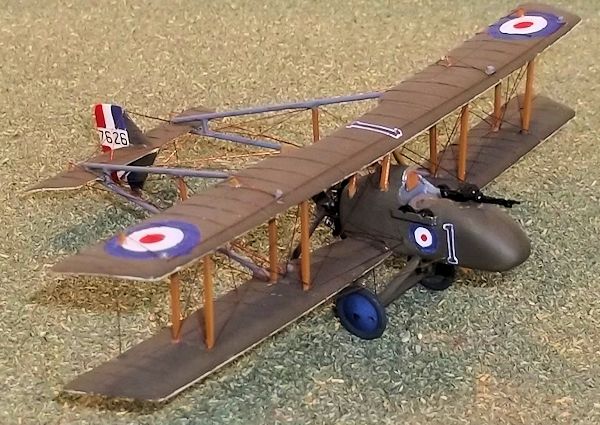 The upper surfaces of this
model were PC10 (mix 5 parts Humbrol 155 matt olive green and 1 part dark earth
or any dark brown; if you want a browner shade of PC 10 just reduce the
proportion of olive green and increase the brown). The lower surfaces were clear
doped linen (3 parts white, 1 part matt 74 and 1 part light grey - again the
shades varied considerably on the real machines so allow for some variation).
The roundels and fin flashes were hand painted - I am not sure where you would
find roundels of suitable size especially for the nacelle, as these are every
small. The serial came from an old set of Almarks transfers. The numerals on the
nacelle and top wing were also hand painted with a fine paintbrush. I have
described the hand painting method for roundels in my article on the Vickers FB
9 Gunbus. The wheel covers were dark blue and the tyres dark grey. The booms
were medium grey, the engine and gun was black and the propellor dark wood with
brass tips. To get a weathered brass look I mixed some Humbrol 8th Army Sand
with yellow (24) until I had the correct shade. I paint my biplanes before
fixing the top wing because they are almost impossible to paint properly
otherwise.
The upper surfaces of this
model were PC10 (mix 5 parts Humbrol 155 matt olive green and 1 part dark earth
or any dark brown; if you want a browner shade of PC 10 just reduce the
proportion of olive green and increase the brown). The lower surfaces were clear
doped linen (3 parts white, 1 part matt 74 and 1 part light grey - again the
shades varied considerably on the real machines so allow for some variation).
The roundels and fin flashes were hand painted - I am not sure where you would
find roundels of suitable size especially for the nacelle, as these are every
small. The serial came from an old set of Almarks transfers. The numerals on the
nacelle and top wing were also hand painted with a fine paintbrush. I have
described the hand painting method for roundels in my article on the Vickers FB
9 Gunbus. The wheel covers were dark blue and the tyres dark grey. The booms
were medium grey, the engine and gun was black and the propellor dark wood with
brass tips. To get a weathered brass look I mixed some Humbrol 8th Army Sand
with yellow (24) until I had the correct shade. I paint my biplanes before
fixing the top wing because they are almost impossible to paint properly
otherwise.
| FINAL CONSTRUCTION |
Start by measuring and cutting
the 504 main struts to the correct length as shown on the plans. Then cement the
four outer wing struts to the lower wing and line them up so that they are
vertical while they dry for a few minutes. Put small drops of glue into the
outer strut holes on the underside of the top wing and lower the wing gently on
to the struts. Now you will need to align the wings and booms and support them
while they dry out - have your supports ready as the wings will droop around
easily and could damage the struts. When this sub-assembly is dry add the
remaining wing struts and the cabane struts, taking care not to damage the
existing assembly. The tail unit should be assembled and allowed to dry before
assembling the wings so that it can be slipped between the ends of the booms at
this stage and glued into place with superglue. An alternative method would be
to leave the booms off the wings until you have glued the top wing into place
and then glue the booms and tail unit as a separate operation, but I think that
this involves manoeuvring too many pieces simultaneously. When the tail assembly
is complete the bo om struts can be glued into place - mine were cut from 20thou
card, and the horizontal tail unit adjustors were short pieces of thin rod. The
undercarriage legs were cut from 20thou card and shaped to aerofoil section. I
allowed a small extension on the lower end to be able to drill a hole for the
axle which was a spare taken from a DH 4 and suitably cut down. Assemble the
legs and axle and glue into the holes under the nacelle. Also glue the generator
and control horns into place now. You will now need to paint the struts,
undercarriage legs and generator, and control horns.
om struts can be glued into place - mine were cut from 20thou
card, and the horizontal tail unit adjustors were short pieces of thin rod. The
undercarriage legs were cut from 20thou card and shaped to aerofoil section. I
allowed a small extension on the lower end to be able to drill a hole for the
axle which was a spare taken from a DH 4 and suitably cut down. Assemble the
legs and axle and glue into the holes under the nacelle. Also glue the generator
and control horns into place now. You will now need to paint the struts,
undercarriage legs and generator, and control horns.
Rigging biplanes can
be a problem - it certainly requires patience but if you have got this far it
should not be beyond you to complete this operation. Start with the fuselage
wires, followed by the wings except aileron wires, booms and then the rudder
control wires and undercarriage bracing. Now the tail bracing and elevator
control wires are fixed, followed by the horizontal boom supports and the
anti-drag wires from the rear of the booms to the forward outer struts. The
aileron control wires under the wings followed by the connectors between the
ailerons and the anti-drag wires on the front, will leave you to finish with the
control wires on the top wing. I used copper wire as I find that this is rigid
and gives the model more strength. Finish the model by cementing the engine and
wheels into place and lastly the machine gun in the nose.
| CONCLUSIONS |
 I am aware that
pusher biplanes are not the most popular models but they do offer a very
different aspect to any collection and they are very important in early RFC
collections. That very few are available in kit form leaves the modeller with no
choice but to build your own and surprisingly they are not as difficult as many
people imagine. They are not for beginners it is true, but considering how much
time and skill people put into super detailing their models, these aircraft
should be within the skill range of many if only they would be prepared to have
a go. This being a small aircraft, it can be a bit fiddly at times, but equally
it is relatively quick and easy (by pusher standards) to build. It is certainly
worth the effort.
I am aware that
pusher biplanes are not the most popular models but they do offer a very
different aspect to any collection and they are very important in early RFC
collections. That very few are available in kit form leaves the modeller with no
choice but to build your own and surprisingly they are not as difficult as many
people imagine. They are not for beginners it is true, but considering how much
time and skill people put into super detailing their models, these aircraft
should be within the skill range of many if only they would be prepared to have
a go. This being a small aircraft, it can be a bit fiddly at times, but equally
it is relatively quick and easy (by pusher standards) to build. It is certainly
worth the effort.
| REFERENCES |
RAF FE 8
by J M Bruce, Windsock DataFile no 74.
Pusher Aces of World War 1 by J Guttman, Osprey Aircraft of the Aces no 88.
September 2013
If you would like your product reviewed fairly and fairly quickly, please contact the editor or see other details in the Note to Contributors.