Gustav Otto was a Bavarian engineer who established a factory for
building aircraft in Munich in the years just before WW1. Unusually
for German designers he focussed on pusher machines, and according
to contemporary British sources these were copies of Farman designs.
In fact this was a little unfair as it would be more accurate to say
that he was inspired by the Farman designs as his machines were
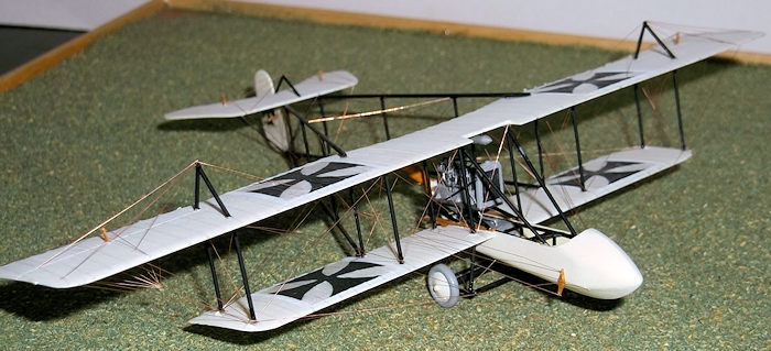
considerably different in outline and construction. Whereas most
contemporary machines were built with wooden frames, Otto used
steel. This was a very marked innovation for the time as was his use
of elevators rather than wing warping which was common on most
contemporary French and British designs. The engine was mounted on a
platform above the rear of the nacelle and was an Argus of 100hp,
again a more powerful plant than most of its non-German
contemporaries. However the basic design went through many
variations over time, as did many other contemporary designs, as
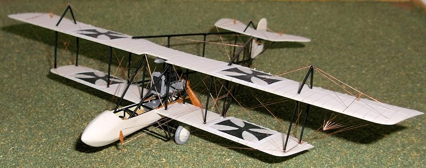
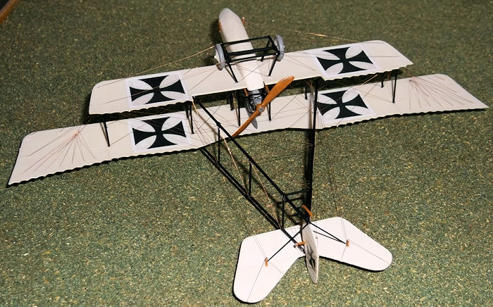
Otto tried to refine and improve the basic idea. There were
variously machines with four fins and rudders, twin two-wheel
undercarriage units and various shapes to the nacelle. One
photograph shows an Otto without any nacelle at all as on the
Bristol Boxkite, with the pilot sitting fully exposed in the front
of the aircraft and the passenger equally exposed behind. It would
seem that by 1914 the design had settled to something like what I
have tried to represent in my model, but I cannot be certain of all
the details as there is little reliable information published in
English. Otto was also the owner of the Ago company which built the
C class of aircraft which was the subject of another scratch build
that I have posted on this site.
 An interesting part of the story of this design involved Flying
Instructor Bruno Büchner who organised demonstration flights to
rally interest in aviation in South-West Africa, then a German
colony, now Botswana. He was given a biplane from the Pfalz-flugzeugwerke,
caller Doppelfalz, and told that after completing his displays he
was to fly overland to East Africa (also a German colony at the time
- now Tanzania), to give shows there. In May 1914, Büchner, his
wife, and a newspaper reporter arrived in Swakopmund with the
Doppelpfalz. He assembled and tested the plane at the coast and flew
to Windhoek. Conditions were far from ideal - the air was too thin
at that altitude and the aircraft was not really suitable for a
tropical environment. It was therefore decided that Büchner should
not fly to East Africa. He continued to performe at a few shows in
the South-West colony and undertook what was for those days long
distance flights to Usakos and Karubib, carrying post bags and even
a passenger. Eventually, the party arrived in Lüderitz by train. The
shows ceased in July when he had the aeroplane shipped in crates to
Dar-es-Salaam.
An interesting part of the story of this design involved Flying
Instructor Bruno Büchner who organised demonstration flights to
rally interest in aviation in South-West Africa, then a German
colony, now Botswana. He was given a biplane from the Pfalz-flugzeugwerke,
caller Doppelfalz, and told that after completing his displays he
was to fly overland to East Africa (also a German colony at the time
- now Tanzania), to give shows there. In May 1914, Büchner, his
wife, and a newspaper reporter arrived in Swakopmund with the
Doppelpfalz. He assembled and tested the plane at the coast and flew
to Windhoek. Conditions were far from ideal - the air was too thin
at that altitude and the aircraft was not really suitable for a
tropical environment. It was therefore decided that Büchner should
not fly to East Africa. He continued to performe at a few shows in
the South-West colony and undertook what was for those days long
distance flights to Usakos and Karubib, carrying post bags and even
a passenger. Eventually, the party arrived in Lüderitz by train. The
shows ceased in July when he had the aeroplane shipped in crates to
Dar-es-Salaam.
Büchner heard about the outbreak of the First World War in
Zanzibar Harbour. He returned to Dar-es-Salaam met the cruiser Königsberg.
On arrival he offered his aircraft to Oberstleutnant Paul von
Lettow-Vorbeck, the commander of the defence forces in German
East Africa. Von Lettow-Vorbeck ordered Büchner to undertake a
scouting mission in the direction of Zanzibar and Bagamoyo.
Flying along the coast he spotted two gunboats which immediately
opened fire and was wounded in the arm. On landing, the plane
struck deep sand and somersaulted. Büchner was thrown clear but
injured; he arrived at his base late in the evening and utterly
exhausted. While he was still in hospital, another officer,
Leutnant Henneberger, had the plane repaired and took off.
However, when he was attempting to la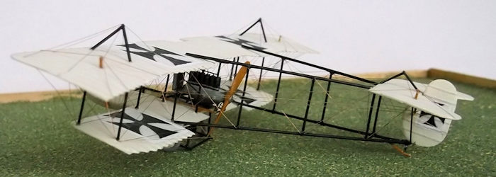 nd the aircraft clipped the
tops of palm trees and crashed killing the pilot even though the
plane was only lightly damaged.
nd the aircraft clipped the
tops of palm trees and crashed killing the pilot even though the
plane was only lightly damaged.
After his recovery Büchner was ordered to fit floats to his
plane and to support the Königsberg, which was then lying
disabled in the Rufiji Delta. The aircraft was rebuilt and
sheet-metal floats were attached. It was then found that there
was insufficient petrol available, and the project was
cancelled. The inventive Büchner fitted the aircraft's engine to
a small-gauge railway goods truck and, with this much admired Schienen-Zepp(Rail-Zepp[elin]),
undertook two goods transport trips to the inland town of
Morogoro. Following the occupation by the British, Büchner and
his wife were interned.
The military service career of these aircraft at home seems
to have been limited to reconnaissance on the Eastern front
by a very few machines. The Army did not like them because
they were considered to be badly constructed and the Navy
ordered several but these seem to have suffered from poor
construction too. However some machines do seem to have been
employed at least in the early months of the war before they
were withdrawn from service.
I started as usual by making a mould for the fuselage
nacelle using the standard push-mould technique. The
frame of the fuselage was thin rod and a simple
instrument panel added with a couple of dials was from
card. A compass from a thick piece of rod was cut and
mounted on the port side of the fuselage, together with
a control column, rudder bar and some seats. A fuel tank
was made from laminated card - this fits under the
engine platform in the rear of the nacelle. A gravity
tank which was under the top wing was made from a
cocktail stick. The engine was constructed from
laminated card for the sump and rod for the cylinders
with various bits of pipework from thin rod or stretched
sprue. The radiator was 40 thou card with the front and
rear scribed to give a pipe effect. The propellor was
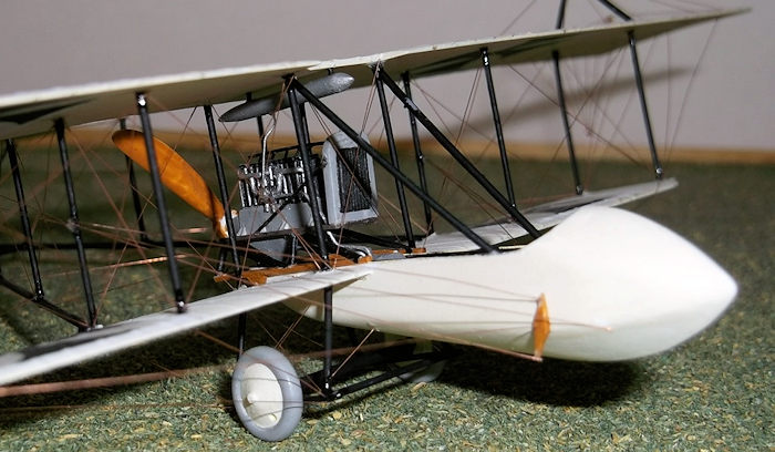 carved from 60 thou card. The engine platform was made
from card and rod and glued to two strips of Evergreen
strip on the sides of the nacelle and top of the lower
wing. This can only be fitted after the lower wings are
in place.
carved from 60 thou card. The engine platform was made
from card and rod and glued to two strips of Evergreen
strip on the sides of the nacelle and top of the lower
wing. This can only be fitted after the lower wings are
in place.
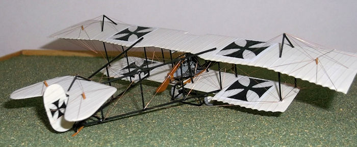
I cut the wings from bent 40 thou card and put on the
ribs from 1mm masking tape, varnished and slightly
rubbed down. Before putting on the ribs the wings were
sanded to an aerofoil section by thinning the trailing
edges and rounding off the leading edges. The shape of
the cut-out of the top wing seems to have varied a
little, as did the location of the gravity tank. The
trailing edge of the lower wing also varied from one
machine to another - I have modelled a simpler style but
there were also curved ones. Ailerons were on the top
wing only. These hung down when the aircraft was on the
ground and the control wires hung loose but as I use
copper wire for rigging this would have been impossible
for me to reproduce so I left my ailerons in the
horizontal position. I also cut the tail surfaces at
this stage.
I joined the lower wings to the fuselage one at a time.
This part is critical because the nacelle tapers so the
wing to fuselage joint must reflect this or the
alignments will be wrong and the model will look
horrible. The inner strut holes go right through the
wing because the undercarriage legs will fit into them
later. On the top wing the outer holes go right through
to mount king posts later. Mark on very carefully the
places where the booms will attach to the wings and
using the end of a round file grind out shallow grooves
that will later take the ends of the booms. The wooden
frames that support the engine platform to the fuselage
and lower wing were fixed next followed by the supports
for the platform. Glue the platform to the supports but
do not put on the engine until the platform and supports
are painted.
I painted the model at this stage. The scheme was
overall clear doped linen with black for the engine
platform. I also put on the markings on both wings and
the rudder. I printed my transfers on clear transfer
sheet having first painted the white square backgrounds
on the wings. I should have printed the crosses on to
white transfer sheet really, but then we can all be
wiser after the event.
The two struts which extend from the leading edge of the top wing to
the nacelle were from rod as was the undercarriage. Wheels from the
spares box, but they could easily have been made from card discs and
rod tyres. The tail skid was made from card, as were the control
horns on the flying surfaces. The
 wing and tail king posts were rod.
Paint all of the struts, booms, king posts and
undercarriage black, tyres light grey and propellor natural wood. Leave
the propellor and wheels off for the moment.Paint all of the struts,
booms, king posts and undercarriage black, tyres light grey and
propellor natural wood. Leave the propellor and wheels off for the
moment.Paint all of the struts, booms, king posts and undercarriage
black, tyres light grey and propellor natural wood. Leave the propellor
and wheels off for the moment. Paint all of the struts, booms, king
posts and undercarriage black, tyres light grey and propellor natural
wood. Leave the propellor and wheels off for the moment.
When the painting and markings were complete I added
the engine and radiator and a fuel pipe from the engine
to the fuel tank in the nacelle. I also added the side
braces between the sides of the radiator and the
platform and a pipe from the rear of the engine to the
rear of the radiator - this goes along the top of the
engine. There are other pipes on the sides of the egine
which can be added now or later. Fixing the wings can be
difficult but life becomes easier if you glue the four
inner struts into the holes in the lower wing and put
small blobs of glue into the inner holes on the
underside of the upper wing. Then gently lower the
upper wing and align the struts so that they are
vertical. Support the wings while this dries out
thoroughly. If this is done properly there should be no
problems with alignment and gap between the wings. When
the structure is dry the other struts can be added
carefully and the structure should be strong enough to
allow this procedure to proceed without problems. Many
people seem to think that building biplanes in this way
is difficult because the structure would be weak but
experiences proves otherwise. I cut my booms from
florists wire as this is stiff enough to hold the model
together and is completely straight, which I do not find
is the case with plastic rod. Fix the booms to the lower
wing first. I placed the model on a plan so I could
align them correctly in the horizontal plane. I then
measured from a side elevation of the plans the vertical
distance between the trailing edge of the wing and the
rear end of the boom. This gives the height of the
support that has to be put under the tail end of the
boom while the glue dries. I use epoxy as it gives me
time to make last moment adjustments and get everything
into the correct position before it hardens. The two
small bracing struts at the rear of the V were from
plastic rod held with superglue. I had drilled a small
hole in the base of the rudder and inserted a small pin
which I now placed into the V of the lower boom, again
with superglue to hold it. Hold the rudder in the
correct position while the
 superglue dries. Then I can
add the upper booms to the top wing joints and brought
the rear ends to form a V on a small nick cut out in the
leading edge of the rudder - this latter joint was superglued. Note that in the horizontal plane the booms
converge towards the rear. The boom struts were be
measured individually with dividers and cut from rod and
put into place with superglue. This structure is strong
when it is all in place.
superglue dries. Then I can
add the upper booms to the top wing joints and brought
the rear ends to form a V on a small nick cut out in the
leading edge of the rudder - this latter joint was superglued. Note that in the horizontal plane the booms
converge towards the rear. The boom struts were be
measured individually with dividers and cut from rod and
put into place with superglue. This structure is strong
when it is all in place.
Paint all of the struts, booms, king posts and undercarriage
black, tyres light grey and propellor natural wood. Leave
the propellor and wheels off for the moment.
For the rigging I used 40 SWG copper wire rolled straight and held
in place with superglue. Measure the distances on the model with a
pair of dividers and cut each length individually. Work
systematically around the model and you are unlikely to miss any.
Place the most inaccessible ones first, and leave the most prominent
and therefore most likely damaged until last. Glue on the propellor
after you have rigged the sides of the booms but before you put in
the cross bracing, and the wheels until after you have rigged the
undercarriage frame but before you put on the under-wing bracing.