Pegasus 1/72 Etrich Taube
| KIT #: | 4010 |
| PRICE: | approx £10 |
| DECALS: | None |
| REVIEWER: | Stephen Foster |
| NOTES: | Short run kit |
| HISTORY |
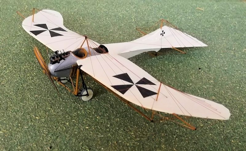
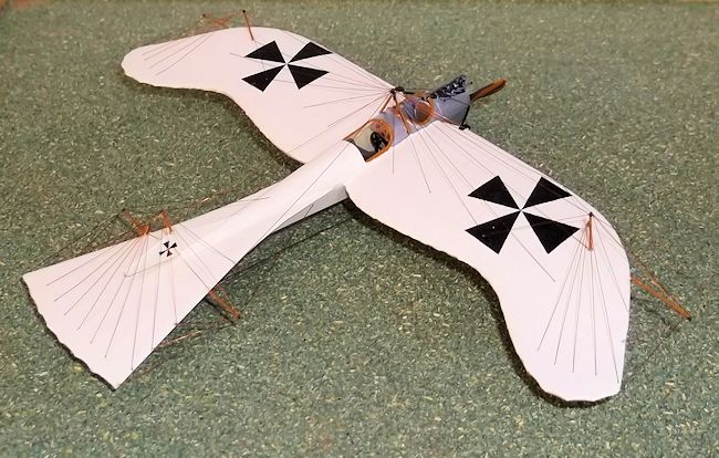
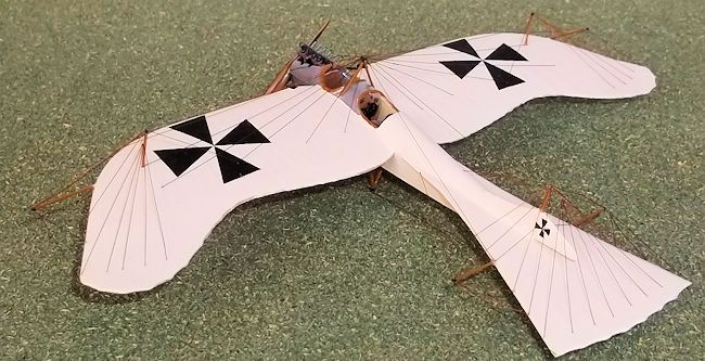
Taube means pigeon or
dove in German and the name is derived from the shape of the wings, although the
original inspiration for this planform came from the leaf of the Zanonia palm.
Igo Etrich was an Austrian who through a series of designs in the first decade
of the 20th century eventually built an aeroplane that became the forerunner of
the later Taube models. Although Etrich produced a number of prototypes, it was
the two seat design which was produced in significant numbers, although every
machine was different as each one was hand-built, and each was an attempt to
improve on its predecessor. Later other companies in Germany produced similar
aircraft, also called Tauben, but many of these were of simpler construction and
had the underwing spar and spar extensions deleted and a markedly reduced amount
of rigging, all of which reduced drag and increased speed.
 and
warping of the wing tips and horizontal tail surface. It was for this reason
that the trailing edges of these machines were very thin: only the forward
three-quarters of the wing had a double thickness of fabric covering while the
the trailing section was a single surface. The undercarriage was in the form of
a twin-forked structure similar to the contemporary designs of L. Bleriot. The
engines varied from 70 to 120 hp, the most numerous being built by Mercedes or
Argus. Radiators were mounted on the front sides of the fuselage and machines
were unarmed. Taube types were used in the early months of the Great War but
were withdrawn in early 1915. Those that were used operationally had for the
most part the simplified structure of the later designs with the underwing spar
removed and a simpler V undercarriage. Lt. von Hiddesen dropped some very small
bombs on Paris in September 1914 from a Taube, and it was a Taube machine that
brought news of the Russian armies movements in East Prussia that led to the
Battle of Tannenburg in 1914. A Taube also carried out reconnaissance sorties
for the German garrison at the siege of Tsingtao in Eastern China in 1914.
Tauben also served in the air units of the Austro-Hungarian armies, although
like their German counterparts they were withdrawn from front line service in
the spring of 1915 but continued to be used for training for about a year
afterwards.
and
warping of the wing tips and horizontal tail surface. It was for this reason
that the trailing edges of these machines were very thin: only the forward
three-quarters of the wing had a double thickness of fabric covering while the
the trailing section was a single surface. The undercarriage was in the form of
a twin-forked structure similar to the contemporary designs of L. Bleriot. The
engines varied from 70 to 120 hp, the most numerous being built by Mercedes or
Argus. Radiators were mounted on the front sides of the fuselage and machines
were unarmed. Taube types were used in the early months of the Great War but
were withdrawn in early 1915. Those that were used operationally had for the
most part the simplified structure of the later designs with the underwing spar
removed and a simpler V undercarriage. Lt. von Hiddesen dropped some very small
bombs on Paris in September 1914 from a Taube, and it was a Taube machine that
brought news of the Russian armies movements in East Prussia that led to the
Battle of Tannenburg in 1914. A Taube also carried out reconnaissance sorties
for the German garrison at the siege of Tsingtao in Eastern China in 1914.
Tauben also served in the air units of the Austro-Hungarian armies, although
like their German counterparts they were withdrawn from front line service in
the spring of 1915 but continued to be used for training for about a year
afterwards.
| THE KIT |
I have built a large
number of conversions recently, particularly pusher types and I wanted to try
something a little different so I thought that a tractor monoplane would be a
good idea. There is a vacuform of the Taube which was released in the 1970's
which is now a very rare bird, but I am not a fan of vacuforms so I bought a
Pegasus injection moulded kit instead. The notice on the box says that this kit
is not a toy and is only recommended for experienced modellers
and collectors: I had been warned. The kit consists of
some trees with plastic parts and some white metal parts for the fuselage
bulkheads, control column, fuselage pylons and undercarriage legs and what
passes for an engine. The spar extensions and struts, axle and exhaust pipes
have to be cut from plastic rod and strut material provided.
 Instruction
number one states remove all parts from the trees and clean them up. The plastic
in this kit is fairly soft so this procedure needs care but is straightforward
with a sharp knife. In some cases I cut the trees with a saw and then removed
the part with a knife before finishing with a file and glass paper: stage one
took an evening to complete. This may be a relative small model with a limited
number of parts but is certainly not a quick build. The parts are well moulded
for a limited run kit, and except for the engine the white metal parts are a
good idea as they add strength to the model and provide better pieces to work
with. The engine is a bit crude but as it is mostly concealed this can be
overlooked by all except the most fastidious modeller. There is a problem with
the wings and tail surfaces however as they are much too thick, especially the
trailing edges, but unless you are prepared to spend another evening sanding
them down this problem is best treated by sanding some of the plastic and
leaving the rest, as much for strength as any other reason. I did replace the
vertical tail surfaces as these were too thick and not really of the correct
shape.
Instruction
number one states remove all parts from the trees and clean them up. The plastic
in this kit is fairly soft so this procedure needs care but is straightforward
with a sharp knife. In some cases I cut the trees with a saw and then removed
the part with a knife before finishing with a file and glass paper: stage one
took an evening to complete. This may be a relative small model with a limited
number of parts but is certainly not a quick build. The parts are well moulded
for a limited run kit, and except for the engine the white metal parts are a
good idea as they add strength to the model and provide better pieces to work
with. The engine is a bit crude but as it is mostly concealed this can be
overlooked by all except the most fastidious modeller. There is a problem with
the wings and tail surfaces however as they are much too thick, especially the
trailing edges, but unless you are prepared to spend another evening sanding
them down this problem is best treated by sanding some of the plastic and
leaving the rest, as much for strength as any other reason. I did replace the
vertical tail surfaces as these were too thick and not really of the correct
shape.
| CONSTRUCTION |
Before assembling the
fuselage the interior needs to be painted. The front end forward of the pilots
cockpit was bare metal, but the bulkheads were plywood, The seats (which are a
little crude but with cleaning up and thinning, passable), should be attached to
the bulkheads with superglue but only after the bulkheads have been filed to fit
the fuselage interior, and thin card strips used to make a slatted cockpit
floor. A bulkhead from card has to be fitted behind the pilot's seat and between
the engine and front cockpit. The hole under the pilot's cockpit, where the
control column extended below the fuselage floor needs to be cleaned up too. The
biggest problem was the engine which does not fit the hole in the front fuselage
as the latter is too small. This can only be resolved by extending the hole to
just in front of the observer's cockpit and putting a piece of 10thou card under
the engine platform to lift it a little. Joining all of the interior parts to
one fuselage half is tricky as the bulkheads have to be filed to make them fit
properly, the engine has to be centred properly on its little platform and the
engine intake on the left side have to fit into the recesses in the fuselage. In
addition superglue is needed to hold the white metal parts and plastic cement
the plastic additions, so a lot of juggling is required. Once you have got the
interior parts to go into the correct places the fuselage halves can be joined
and when dry the joint filled and cleaned up. I replaced the vertical tail
surfaces with pieces cut from 20thou plastic card, using a scale plan to get the
correct shape. Do not cement the upper surface until you have painted the cross
as this is very small and the rudder is inaccessible once it is fitted. The
horizontal tail surface recess will need to be opened with a knife and file: do
this carefully to keep the opening symmetrical and so that you do not
 remove too
much plastic. When you are satisfied with the fit thin down the trailing edge
and then glue into place and when dry fill and sand down the joints. Drill a
hole in the nose to take a pin on the propellor later.
remove too
much plastic. When you are satisfied with the fit thin down the trailing edge
and then glue into place and when dry fill and sand down the joints. Drill a
hole in the nose to take a pin on the propellor later.
The wing trailing edges need thinning - it is up to you how much plastic you remove but the more the better really. Now drill the holes on the undersides of the wings to take the spar support struts, and drill two holes right through the wings for the king posts. Also drill a hole in the end of each wing for the spar extensions and in the horizontal tail surfaces at the same time. I decided to strengthen the wing joints by adding a thin piece of wire which acted as a spar between the cockpits. Accurately measure the wings and drill a shallow horizontal hole in each, making sure that they are directly opposite each other. The hold the wing to the fuselage and mark on the positions of the holes on the fuselage sides before drilling the holes. Insert a short piece of wire into the fuselage and superglue into place. Trim the ends of the wire if they are too long before putting superglue on one end. Take a wing and add a small amount of cement to the edge which will attach to the fuselage side and push the wing on to the end of the wire and against the fuselage side. Get everything properly aligned and support this wing while it dries out thoroughly. Repeat this operation on the other wing. When the wings are dry fill the joints and rub down.
| COLORS & MARKINGS |
Now is the time to paint
the model, especially if you want to put on markings as the wings will not be
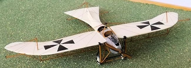
accessible when the underwing spar is added. These aircraft were overall clear
doped linen with bare metal panels around the nose and upper fuselage between
the cockpits. I used a mixture of white with a little Humbrol 81 (ratio of about
3:1 but the exact proportions are not terribly important). A small amount of
light grey also helps to give a slightly darker tone of dirty linen. The metal
was Humbrol silver with medium grey mixed in - about 3 parts silver to one part
grey. The radiators were brass, tyres light grey (or off-white on some early
machines), undercarriage legs, forks and axle black, and the remaining struts
and pylons brown. I hand painted the crosses as I did not have a suitable source
for them. I chose the simpler early straight sided crosses - painting crosses
with curved sides was a step too far! Measure carefully where the centre of the
cross should be and mark it with the point of a divider. Now draw a cross the
arms of which are the exact size of the finished cross, centred on the hole from
the divider. At the end of each of the four lines draw a second line at 90
degrees which is the exact length of the outer edge of the cross:
 make sure
that the original cross arm bisects the new line exactly. When this has been
done on each of the ends of the original cross, the sides of the cross arms can
be drawn from the ends of short outer lines through the hole at the centre. This
will give you four equal sided triangles with their apexes at the centre. I
scribed these lines with the point of a divider and then painted the black with
a fine paintbrush and slightly thinned paint. The cross on the upper rudder was
the most difficult because it was so small but it can be done if it is not
attached to the model. If you choose to model a later machine with the white
squares and Maltese cross form I suggest that you try to print your own or use
the transfers from the Revell Fokker E 111 for the wings. Alternatively you
could use the Pegasus German WW1 crosses sheet if you can find a set on the
internet. Strictly the crosses form the Revell EIII are fractionally too small
but only the purist would notice. However you will need a cross and white square
on both the upper and lower rudders and I do not know where such small crosses
can be obtained, apart from home-made sources. Note too that if you present your
model with crosses on white squares then it will not be an Etrich taube but one
from another manufacturer and some minor alterations to the kit will have to be
made which are not covered here.
make sure
that the original cross arm bisects the new line exactly. When this has been
done on each of the ends of the original cross, the sides of the cross arms can
be drawn from the ends of short outer lines through the hole at the centre. This
will give you four equal sided triangles with their apexes at the centre. I
scribed these lines with the point of a divider and then painted the black with
a fine paintbrush and slightly thinned paint. The cross on the upper rudder was
the most difficult because it was so small but it can be done if it is not
attached to the model. If you choose to model a later machine with the white
squares and Maltese cross form I suggest that you try to print your own or use
the transfers from the Revell Fokker E 111 for the wings. Alternatively you
could use the Pegasus German WW1 crosses sheet if you can find a set on the
internet. Strictly the crosses form the Revell EIII are fractionally too small
but only the purist would notice. However you will need a cross and white square
on both the upper and lower rudders and I do not know where such small crosses
can be obtained, apart from home-made sources. Note too that if you present your
model with crosses on white squares then it will not be an Etrich taube but one
from another manufacturer and some minor alterations to the kit will have to be
made which are not covered here.
| MORE CONSTRUCTION |
When you have completed
the painting cut the under-wing spars from the strut material and the support
struts and king-posts from the rod, and fix the underwing spars into place. I
did this by measuring the king post accurately and inserting as one piece into
the wing. Then I cut the spar and glued it to the end of the king post and the
fuselage and finished by measuring the support struts with dividers and cutting
them to fit before gluing into place. This exercise is also tricky and should be
done carefully. The radiators can be fixed to the fuselage using superglue at
this stage. The undercarriage is next and the diagram in the instruction sheet
is misleading. This is a complex structure to describe but it consists of two
forks which hold the axle, two vertical posts in front with a cross-bracing
between them at the bottom, and two arms between the ends of the axle and the
forward posts. Two V struts attach to the fuselage and a joint at the bottom of
the forward vertical posts. Start by opening the arms on the undercarriage forks
until the wheels will fit properly: these are white metal and bend easily. Add
the cross bracing between the arms of the forks of the main undercarriage legs,
using two short lengths of rod supplied in the kit. I replaced the forward white
metal vertical posts with thick plastic rod. Cut an axle and forward cross
bracing member from rod supplied in the kit. Now cement the vertical posts to
the plates on the leading edges of the wings and the V struts (also in white
metal) between the fuselage and the base of the posts. Fix the cross bracing
between the bottoms of the posts and ensure that all is square and allow to dry.
Superglue the main undercarriage legs to the plates on the wing and angle them
back a little so that the small horizontal forks (white metal) can be attached
to the base of the vertical posts, and glue the base of the forks on to the main
legs. Insert the wheels into the forks and finally glue the axle into place and
allow the whole assembly to dry out thoroughly. This is another tricky set of
operations but if they are tackled systematically and carefully a neat job can
be achieved and it is stronger than it looks. Finally add the tail skid (also
white metal), the spar extensions and exhaust pipes (cut from rod supplied in
the kit), and lower fuselage pylon and nose bracing struts (white metal). Drill
a hole in the rear of the propellor and glue a short piece of rod into the rear
to make a pin. Leave the upper pylon and the upper rudder post until later. I
now painted the wooden parts of the undercarriage assembly and the spar
extensions, pylon, skid and propellor. (I had painted the undercarriage forks
and wheels prior to assembly).
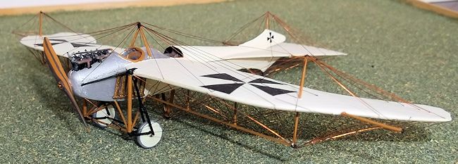
There is a great deal of
rigging on this model: I have made several pushers and even the Sopwith Gunbus
did not have as many wires as this one! However the pattern is repetitive so it
is not as difficult as
 it may
first appear. Before you start decide whether you wish to put in in all of the
wires or only representative ones. Then work methodically on one part of the
model at a time, putting in the least accessible wires first and leaving the
most exposed, (the wing and tail bracing from the spar extensions, and the nose
bracing until last). I also started on the underside and rigged all of this,
leaving the upper fuselage pylon and upper rudder post off because these can be
easily knocked off. (I managed to knock off a tail and wing spar extension too -
great care is needed with this model as it seem to have parts sticking out in
all directions!) I used the following procedure which made sure that I did not
leave out any wires or do too much damage to the completed parts:
it may
first appear. Before you start decide whether you wish to put in in all of the
wires or only representative ones. Then work methodically on one part of the
model at a time, putting in the least accessible wires first and leaving the
most exposed, (the wing and tail bracing from the spar extensions, and the nose
bracing until last). I also started on the underside and rigged all of this,
leaving the upper fuselage pylon and upper rudder post off because these can be
easily knocked off. (I managed to knock off a tail and wing spar extension too -
great care is needed with this model as it seem to have parts sticking out in
all directions!) I used the following procedure which made sure that I did not
leave out any wires or do too much damage to the completed parts:
1. Mark on to the wing and tail surfaces the points
where the ends of a wire need to be attached and make a tiny hole with the sharp
point of a set of dividers. I use copper wire and superglue: a small drop of
glue on the end of the wire will attach the wire to the hole.
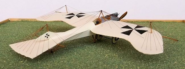
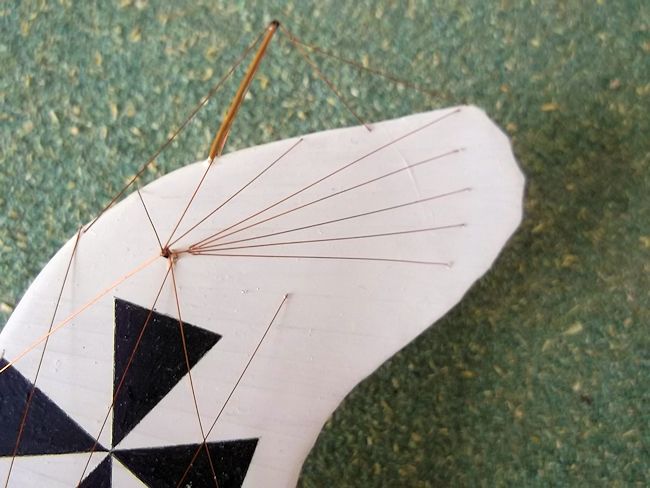
2. Rig the underwing spars - just the vertical wires;
3. rig the underwing spar supports from the wing
leading edge and to the rear spar;
4. put on the aileron control wires from the king
posts. Do this by gluing the centre wire first followed by the two inner and
then the two outer wires (see photos);
5. now the underwing spar extension wires;
6. tail unit control wires from the rudder post.
Start by accurately measuring the length of the two inner wires using dividers.
Glue the ends to the holes in the tail surface and bring the forward ends to the
point of a v and glue together. Cut a piece of wire approx. 5mm long and glue
one end to the rudder post and one to the apex of the v - hold it in place while
it dries. Now add the outer control wires one at a time working outwards and
ensuring that each wire attaches to the same place at the apex of the v. Tiny
drops of superglue on the ends of the wires are enough to hold them in place;
7. complete the remainder of the underside rigging
and control wires to the under fuselage pylon from the nose, tail and wings;
8. carefully turn the model over and glue the upper
fuselage pylon and upper rudder post into place. Repair any broken spar
extensions!
 . start
on one wing and rig the bracing from the pylon to the rear wing spar, starting
with the shortest wire, and put in each wire until you reach the king post and
then rig the leading edge of the wing, also starting with the shortest wire;
. start
on one wing and rig the bracing from the pylon to the rear wing spar, starting
with the shortest wire, and put in each wire until you reach the king post and
then rig the leading edge of the wing, also starting with the shortest wire;
10. then rig the control wires from the king post,
and the bracing wires to the wing edges from the king post;
11. repeat the above for the other wing and put on
the forward bracing from the pylon to the nose;
12. rig the upper tail surface starting with the
control wires from the rudder post, then the bracing wires from the fin to the
horizontal surfaces, control wires from fuselage spine to rudder and bracing
from the pylon to the base of the spar extensions;
13. starting at the tail work your way around the
model adding all of the remaining spar extension bracing wires to the tail,
fuselage and wings. Last of all add the bracing from the base of the
undercarriage vertical posts to the nose.
This may not make much sense at first reading, but if
you are attempting to rig this model, things will become obvious as you proceed.
To complete the model
cement the propeller to the nose and touch in any paintwork as necessary, making
sure that you do not knock off or damage any wires in the process!
| CONCLUSIONS |
This was not an easy
model to build and I would not recommend it unless you have experience with
conventional kits and perhaps some experience with detailing, conversions or
scratch building as it is not one for those who are faint heated or want a quick
finish. Although it looks simple it took me nearly two months to complete, as
long in fact as a pusher conversion. You do not have to complete all of the rigg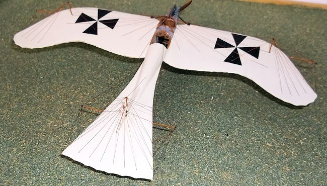 ing
of course - add what you want to, but the effort was worthwhile in my opinion
even though it took a long time. In fact it was actually easier than some
pushers and other biplanes because all of the points of attachment are easily
accessible and most of the operations are repetitive and straightforward. Only
the control wires gave any real challenge which was overcome by a little care, a
lot of patience, accurate measurement from the model, some bad language (but
less than you might expect), and an eye loupe (magnifier) on my spectacles. In
terms of accuracy and time spent making it I think that this offers good value
for money. In my opinion this is a much more interesting and eye-catching
subject than the standard WW1 or WW2 subjects, or even post WW2 models that sit
in so many cabinets, striking though many of those models are. I like a model
that is challenging and different - this was a real challenge and it is very
different.
ing
of course - add what you want to, but the effort was worthwhile in my opinion
even though it took a long time. In fact it was actually easier than some
pushers and other biplanes because all of the points of attachment are easily
accessible and most of the operations are repetitive and straightforward. Only
the control wires gave any real challenge which was overcome by a little care, a
lot of patience, accurate measurement from the model, some bad language (but
less than you might expect), and an eye loupe (magnifier) on my spectacles. In
terms of accuracy and time spent making it I think that this offers good value
for money. In my opinion this is a much more interesting and eye-catching
subject than the standard WW1 or WW2 subjects, or even post WW2 models that sit
in so many cabinets, striking though many of those models are. I like a model
that is challenging and different - this was a real challenge and it is very
different.
September 2014
Copyright ModelingMadness.com. All rights reserved. No reproduction in any form without express permission from the editor.
If you would like your product reviewed fairly and fairly quickly, please contact the editor or see other details in the Note to Contributors.