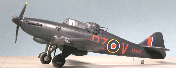
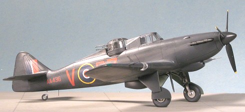
Classic Airframes 1/48 Defiant NF.II
| KIT #: | 481 |
| PRICE: | $49.95 MSRP |
| DECALS: | Two options |
| REVIEWER: | Scott Van Aken |
| NOTES: | Multimedia kit with resin parts. |
| HISTORY |
As many of you already know, the
Boulton Paul Defiant was a test of the idea of a 'turret fighter' whose
offensive armament was located in a powered turret. The theory was that
this would make for a much more effective aircraft, especially against
bombers, as the guns would be free to fire on whatever enemy plane was
around and not just the one in front. When first set upon by the Luftwaffe,
the result was a lot of German planes knocked out of the skies. They just
weren't expecting to be fired upon when sneaking up from the rear. After a
few similar events, the Germans got wise and it was all over for the
Defiant as 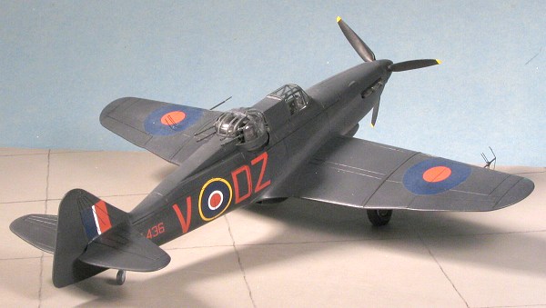 a day fighter for they just weren't up to the task when set upon
by an enemy who knew what to expect. The plane was just too slow and not
maneuverable enough to cope. When attacking bombers, it needed escort so
what was the point.
a day fighter for they just weren't up to the task when set upon
by an enemy who knew what to expect. The plane was just too slow and not
maneuverable enough to cope. When attacking bombers, it needed escort so
what was the point.
It was decided that perhaps it would make for a good night fighter. No worries about marauding 109s and by that time major part of the Battle for Britain was over and the Germans has switched to a night bombing campaign so why not put the Defiant to some use. Defiant I airframes equipped with an early AI Mk IV radar system were sent into the night skies. While not exactly the outstanding success that all had hoped, it did achieve a modicum of success with the first kill being in December of 1940.
Meanwhile, the more powerful Defiant II with a Merlin XX in place of the earlier Merlin III was coming off the production lines. Though the Defiant was a hopeless day fighter, the thought was that it was better to have an inadequate aircraft rather than none at all so production continued. The Mk II had a larger lower cowl intake, a larger radiator and a larger fin/rudder. Those used for night fighting were originally outfitted with the AI. Mk IV radar but soon switched to the improved AI Mk. VI. Eventually the Defiant was removed from all night fighting duties by the coming of the Beaufighter and Mosquito to handle that task. However, the NF Defiants were the among the first and helped to develop tactics and train crews who were much more successful in later years.
| THE KIT |
Please visit the preview for a description of what is in the kit.
| CONSTRUCTION |
 With kits that include resin parts,
the first thing I do is to get all the major resin pieces together and
remove the resin mold sprues. This gets what is probably the most tedious
part of the construction out of the way. I usually wait on the smaller
resin bits until I need them as it keeps me from having them disappear (the
carpet gnomes are much more attracted to loose parts than those on sprues).
With kits that include resin parts,
the first thing I do is to get all the major resin pieces together and
remove the resin mold sprues. This gets what is probably the most tedious
part of the construction out of the way. I usually wait on the smaller
resin bits until I need them as it keeps me from having them disappear (the
carpet gnomes are much more attracted to loose parts than those on sprues).
Once I had sawn free the wheel wells,
cockpit, instrument panel, seats and side panels, I started into a bit of
assembly by gluing together the wheels and the tail plane inserts. Then I
glued the seat and control stick to the cockpit floor. I didn't see
anything that would be a mounting point for the control stick so once the
seat was in place, I selected a spot and glued in the control. Then it was
time to test fit the interior bits. The side panels are shown in the
instructions as going the length of the cockpit, but the actual parts are
only about 2/3rds of that length, making proper positioning a bit of a
quandary. Rather than screw things up, I'll pa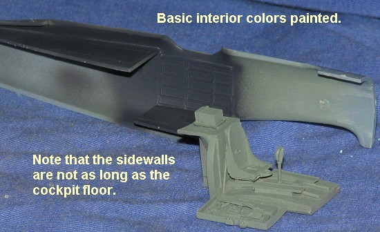 int all the bits and then
when it comes time to actual installation, make up my mind on where things
go. It isn't as big a problem as one would think as the main interior can
be properly situated by aligning the back of the turret housing.
int all the bits and then
when it comes time to actual installation, make up my mind on where things
go. It isn't as big a problem as one would think as the main interior can
be properly situated by aligning the back of the turret housing.
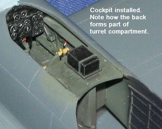
Meanwhile, the gunner's floor and the
upper rear section were glued in place. Test fitting the fuselage halves
showed that the floor is too narrow to fit between the two mounting areas
in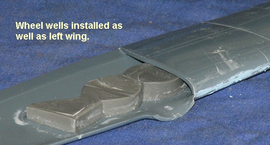 the fuselage so I glued one side in place and got it as flat as I could.
This part will nearly disappear once the turret is installed. I also glued
the wheel wells in place. The left well fit beautifully, but the right one
is a tad short (or the opening isn't the exact same size). Super glue was
used in this case. I also glued on one of the wings just to see how well it
fit and the fit is really quite good. No need to sand on the well to get it
to fit. At this time I did a bit of preliminary painting by painting the
cockpit section, wheel
the fuselage so I glued one side in place and got it as flat as I could.
This part will nearly disappear once the turret is installed. I also glued
the wheel wells in place. The left well fit beautifully, but the right one
is a tad short (or the opening isn't the exact same size). Super glue was
used in this case. I also glued on one of the wings just to see how well it
fit and the fit is really quite good. No need to sand on the well to get it
to fit. At this time I did a bit of preliminary painting by painting the
cockpit section, wheel 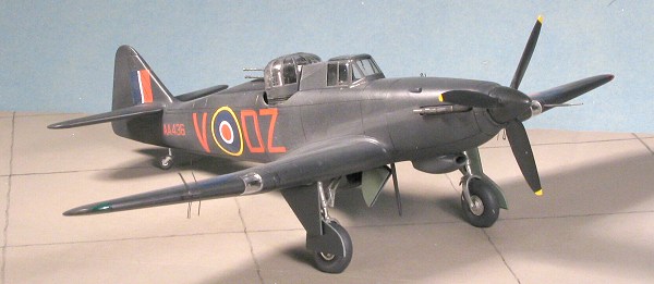 wells and inside gear doors with RAF Interior Green.
The rear gunners section is supposed to be matte black-grey so I uses Floquil's weathered black for this section. As a note, the instructions
state that the wheel wells could be either Interior Green, Aluminum or the
underside color, so there are a number of options in this regard.
wells and inside gear doors with RAF Interior Green.
The rear gunners section is supposed to be matte black-grey so I uses Floquil's weathered black for this section. As a note, the instructions
state that the wheel wells could be either Interior Green, Aluminum or the
underside color, so there are a number of options in this regard.
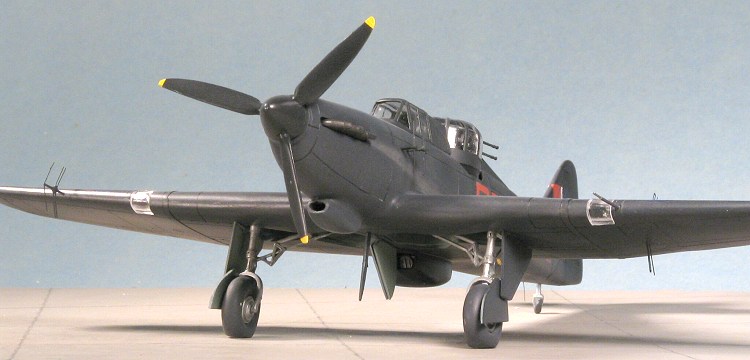
While all that was drying, I decided
to do a few more subassemblies. The Mk II variant uses a broader set of
prop blades and a shorter spinner than the Mk.I. All this is taken care of
in the kit so, since the prop and spinner were to be black, I assembled
them. This, so much like other short run kits, has a separate prop and
spinner. The spinner needs to have the prop openings enlarged as they are
too small. A circular file works well for this. Once I was sure all the
parts would fit, gluing them was not a problem. Getting the blades aligned
was. I know that building an alignment board for these isn't difficult, but
it would be nice to have on included in the kit instructions. Just a
suggestion.
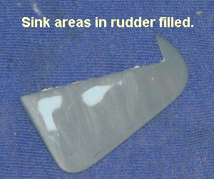
I had also filled in the sink areas on the larger rudder so sanded those off. Took off some of the rib detail as well, but I don't think it will be very noticeable. Using the slightly smaller rudder won't help as it was similarly afflicted. I also installed the radiator grilles into the larger housing. Forward one fit very well, but the aft one was too wide and needed to be trimmed down to fit. I cleaned up several parts on the sprue and painted those that were to be aluminum (wheels, struts, landing lights) with Alclad II Aluminum. I also took this opportunity to spray the prop. Starting with the tips, these were sprayed Floquil Reefer White and when dry, a suitable yellow was sprayed over them. The tips were then masked when the paint had cured and the rest of the prop and spinner sprayed black.
Returning to the rest of the kit, I
then painted on some detail, gave the parts a wash of dirty thinner and
then a light dry-brush with some aluminum. In the nose section, I installed
the rad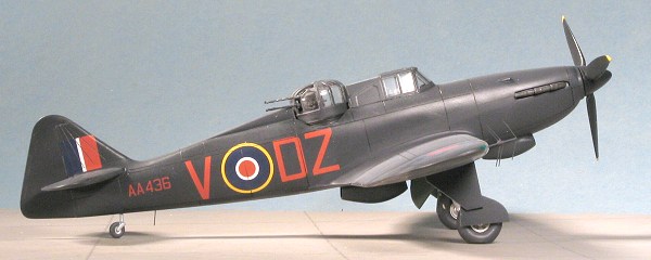 iator screen and the
backing strips for the exhaust. I suggest attaching these strips only at
the ends rather than getting them flush or they will end up curved and give
fit problems when you put in the exhaust.
iator screen and the
backing strips for the exhaust. I suggest attaching these strips only at
the ends rather than getting them flush or they will end up curved and give
fit problems when you put in the exhaust.
I then sawed the major pieces for the turret from their resin pour stubs. This is basically four parts; the main turret, the gunner's seat and the two main gun sections (minus the barrels which are separate). One of my guns had a small bit broken during shipment, but I don't think it will be that noticeable. Assembly of the turret bits is really quite simple. I also test fit the radiator bath to the underside of the wing. There are some raised guide sections on the lower wing, but they are too wide and too short for the Mk.II radiator so those raised sections were sanded off. I also noted that the grilles are too short as there is a gap at the top that will let you see through the radiator section. That will be blocked with a small section of card prior to gluing it on. I also cut the already painted landing gear legs and retraction struts. A lot more clean-up was needed in preparation for re-painting in aluminum.
 At
this time it was to the point of installing the interior. I discovered
through some intensive head-scratching that the side panels need to fit up
against the rear bulkhead of the cockpit floor. If not, there will not be
sufficient room for the instrument panel to be glued in place due to the
bits that stick up from one of the side panels. To make sure that all fit
properly, I aligned the cockpit by the placement of the bit that forms part
of the turret housing.
At
this time it was to the point of installing the interior. I discovered
through some intensive head-scratching that the side panels need to fit up
against the rear bulkhead of the cockpit floor. If not, there will not be
sufficient room for the instrument panel to be glued in place due to the
bits that stick up from one of the side panels. To make sure that all fit
properly, I aligned the cockpit by the placement of the bit that forms part
of the turret housing.
With the cockpit in place, I flooded
a few areas with super glue to be sure it would fit. I then glued on the
other fuselage half. It fit fairly well though I did have to use filler on
the joins. I then glued in the instrument panel by inserting it through the
opening in the front. Next, I slid the fuselage onto the wing assembly. Fit
here was quite goo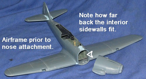 d
and by slightly spreading the forward fuselage, I was able to get a
filler-free join on the roots. This would haunt me a bit later. There was a
gap at the rear underside wing/fuselage join that was filled. Next, I glued
on the rudder (be sure to use the proper rudder for the night fighter. They
look the same but the Mk.II rudder is a bit larger. Then the tail planes
were butt joined onto their roots. The right side needed a bit of trimming
on the bit just aft of the root as it was too long. The join seams were
then filled.
d
and by slightly spreading the forward fuselage, I was able to get a
filler-free join on the roots. This would haunt me a bit later. There was a
gap at the rear underside wing/fuselage join that was filled. Next, I glued
on the rudder (be sure to use the proper rudder for the night fighter. They
look the same but the Mk.II rudder is a bit larger. Then the tail planes
were butt joined onto their roots. The right side needed a bit of trimming
on the bit just aft of the root as it was too long. The join seams were
then filled.
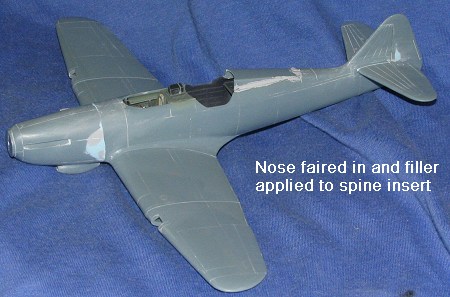
 I now moved to the front of the
aircraft. Though I shouldn't have been surprised, by widening the forward
fuselage to get a good wing root join, I made that area a bit wider than
the nose. Perhaps I should have glued the nose halves to the fuselage
halves, but I didn't and so have to deal with the diameter difference.
Having said that, I applied the first of what were undoubtedly to be
several layers of filler. It really wasn't as onerous as I'd originally
thought and about three applications were all that was needed. The
obliterated panel lines were rescribed and I turned to the radiator bath.
This had a small piece of card glued in to cut back on the 'see through'
and it was glued in place.
I now moved to the front of the
aircraft. Though I shouldn't have been surprised, by widening the forward
fuselage to get a good wing root join, I made that area a bit wider than
the nose. Perhaps I should have glued the nose halves to the fuselage
halves, but I didn't and so have to deal with the diameter difference.
Having said that, I applied the first of what were undoubtedly to be
several layers of filler. It really wasn't as onerous as I'd originally
thought and about three applications were all that was needed. The
obliterated panel lines were rescribed and I turned to the radiator bath.
This had a small piece of card glued in to cut back on the 'see through'
and it was glued in place.
Moving to the top of the airframe, I
masked all the transparencies. I put the turret greenhouse atop the rest of
the mount and then glued the two halves. Since the standard glue won't
stick to the resin mount, it made things quite a bit easier. At this
juncture, I noticed that the greenhouse on the turret seemed a bit high.
Digging through my copy of William Green's ancient 'Famous Fighters' books,
it was obvious that it was too tall. I also noticed that I had some room to
play with so I got a coarse sanding stick and in about 5 minutes had sanded
the greenhouse down to where the gun mount hit the top of it. Thanks to the
thickness of the clear bits, no worries about breaking it while sanding. I
then sanded on the seam between the two greenhouse halves and got it ready
to paint. In the meantime, I drilled out the barrel attachment areas on the
gun mounts
 and
then glued the gun barrels in place. These will easily slide through the
openings in the turret greenhouse so I drybrushed the turret assembly and
put it in a safe place until the end of the build.
and
then glued the gun barrels in place. These will easily slide through the
openings in the turret greenhouse so I drybrushed the turret assembly and
put it in a safe place until the end of the build.
The next item was the rear spine insert. This is a very loose fit and that is probably due to the width of the upper inner fuselage insert. I would suggest when doing this kit that you sand down one side of that inner piece just a tad so that the spine insert will be a tighter fit. The part was glued in and then all the more recent additions had some filler applied to the seams. Normally you'd see a thin gap on the spine insert, but on mine it would be way too large, hence the filler. With that done the canopy was glued in place. It would have been nice to have this be able to be displayed open without cutting it as much of the cockpit work will not be easily seen with it closed.
The wheel wells, turret well and aft part of the canopy were filled with tissue as it was time for the first round of painting.
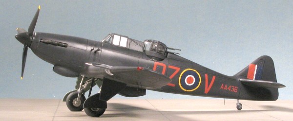
| COLORS & MARKINGS |
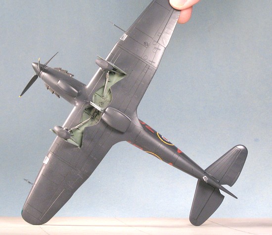 Black airplanes are difficult to
paint. That may seem like a contradictory statement at first, but really,
there is little that is as boring as a solid black plane. Monochrome
finishes are basically all that way, so the trick is to change the shade.
In this case, I took some Floquil Weathered Black, which is a bit darker
than RLM 66, and added black to it until I got an extremely dark grey.
Then, I proceeded to give the model a good coat of the stuff. It also acts
as a great primer so I was able to spot a few places that needed work.
While that was drying, I did a bit more fiddling on other parts and that
included getting the prop ready for installation. I was to have installed a
prop shaft then trapped the prop between the fuselage halves during that
stage of the construction, but I rarely do so. In this case, I also had to
drill the hole in the back of the spinner as it was filled. Once drilled
out, I installed the prop shaft and when it was dry, cut off the hold-back
so I could just slide it in place.
Black airplanes are difficult to
paint. That may seem like a contradictory statement at first, but really,
there is little that is as boring as a solid black plane. Monochrome
finishes are basically all that way, so the trick is to change the shade.
In this case, I took some Floquil Weathered Black, which is a bit darker
than RLM 66, and added black to it until I got an extremely dark grey.
Then, I proceeded to give the model a good coat of the stuff. It also acts
as a great primer so I was able to spot a few places that needed work.
While that was drying, I did a bit more fiddling on other parts and that
included getting the prop ready for installation. I was to have installed a
prop shaft then trapped the prop between the fuselage halves during that
stage of the construction, but I rarely do so. In this case, I also had to
drill the hole in the back of the spinner as it was filled. Once drilled
out, I installed the prop shaft and when it was dry, cut off the hold-back
so I could just slide it in place.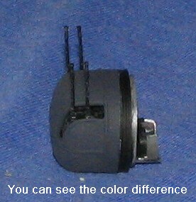
With the first round of painting dried, I filled and sanded the few additional glitches that I found. At this time, I also drilled some of the holes I'd need for bits later on. This included holes for the right radar antenna, the pitot tube (which I have to make), the radio mast between the wheels, the tail wheel and a small antenna just forward of that (which I have to make). I also glued the greenhouse on the turret and painted the base of the turret with flat black so that you can see the difference in my extremely dark grey and black. Going back through the instructions, I looked for other things I might have missed and found that I forgot the mud guards and the oleo scissors for the landing gear. These were then glued in place and the gear repainted once dry. I also gave the model a couple of coats of Future (clear acrylic gloss) in preparation for the decals later on.
 Back to the paint shop went I to
finish with the overall color and repaint the gear legs. When that had
dried, I brought the kit to the workbench again to install the landing
gear. I first glued in the tail wheel, then applied Bare Metal Foil Chrome
on the main gear oleos. Test fitting the gear to the mounting holes, it was
apparent that the gear legs were too large. I used a sanding stick to sand
down the diameter of the lower legs until they fit. These were then glued
in place along with the two support struts. Either the support struts are
too short or the gear legs too long as they don't match up directly to
where they are supposed to go according to the instructions. I'd recommend
making the struts a bit shorter than they are by about 1/16 to 1/8 inch so
that the support struts will fit as they should.
Back to the paint shop went I to
finish with the overall color and repaint the gear legs. When that had
dried, I brought the kit to the workbench again to install the landing
gear. I first glued in the tail wheel, then applied Bare Metal Foil Chrome
on the main gear oleos. Test fitting the gear to the mounting holes, it was
apparent that the gear legs were too large. I used a sanding stick to sand
down the diameter of the lower legs until they fit. These were then glued
in place along with the two support struts. Either the support struts are
too short or the gear legs too long as they don't match up directly to
where they are supposed to go according to the instructions. I'd recommend
making the struts a bit shorter than they are by about 1/16 to 1/8 inch so
that the support struts will fit as they should.
With the struts well in place and pretty solidly done, it was time for the wheels. I drilled the back of the resin wheels I bought (if you recall, I lost one of the kit wheels) and test fit them. Two things; one the axles are a touch long so those were trimmed back. Second is that the angle of the axles are not the same. The fix is quite easy. I struck a match, let it burn a bit then blew it out. The hot end was brought near the out of align axles (which had the wheels pressed on), and then when the plastic became a bit pliable, they were bent to where the wheels were properly aligned. I took great care not to get the plastic too hot as it would have spelt disaster. As it is, with the design of the lower gear, it is a bit wobbly for only a relatively thin strip of plastic holds up the model.
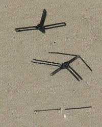 I next decided to build up some of
the radar antennas. You are given two of the three stand-off mounts; the
one on the right wing and one of the fuselage mounts. The third you need to
make from scrap. I built the wing tip one first. This is an 'arrowhead'
array and there seemed to be a small tab on the inside of the forward
antenna, so I drilled out the tip of the resin mount with a #80 drill bit
then glued on the antenna. Two other swept back antennas fit on the bulge
about half way down the mount. I then did the one fuselage mount. Again,
the antennas are butt glued so I have to be really careful handling them as
the antennas bend so very easily. The last one was building the mount for
the second fuselage antenna. This turned out to be pretty easy. I just cut
a square from 40 thousands card, held one end in a pair of tweezers and
filed the majority of it with a sanding stick until it was fairly thin.
Then a bit of trimming to get the right length, drilled hole in the square
end with a #80 drill bit and slid in the etched antenna elements. A lot
easier than I'd thought.
I next decided to build up some of
the radar antennas. You are given two of the three stand-off mounts; the
one on the right wing and one of the fuselage mounts. The third you need to
make from scrap. I built the wing tip one first. This is an 'arrowhead'
array and there seemed to be a small tab on the inside of the forward
antenna, so I drilled out the tip of the resin mount with a #80 drill bit
then glued on the antenna. Two other swept back antennas fit on the bulge
about half way down the mount. I then did the one fuselage mount. Again,
the antennas are butt glued so I have to be really careful handling them as
the antennas bend so very easily. The last one was building the mount for
the second fuselage antenna. This turned out to be pretty easy. I just cut
a square from 40 thousands card, held one end in a pair of tweezers and
filed the majority of it with a sanding stick until it was fairly thin.
Then a bit of trimming to get the right length, drilled hole in the square
end with a #80 drill bit and slid in the etched antenna elements. A lot
easier than I'd thought.
 I then stuck on the gear doors, and
noticed, to my horror, that once again, I'd put the landing gear on the wrong side. Haven't a clue why I did that as I
thought I'd made darn sure they went on the proper sides! I really had no
choice but to try to work them loose and put them on the proper sides. I
had success with one, but the other snapped off. That one had to be drilled
out and a small section of paper clip installed so that it could be
installed. The other side needed to have the well drilled. Once that had
been accomplished, the gear, support struts and the doors were re-glued
back into place.
I then stuck on the gear doors, and
noticed, to my horror, that once again, I'd put the landing gear on the wrong side. Haven't a clue why I did that as I
thought I'd made darn sure they went on the proper sides! I really had no
choice but to try to work them loose and put them on the proper sides. I
had success with one, but the other snapped off. That one had to be drilled
out and a small section of paper clip installed so that it could be
installed. The other side needed to have the well drilled. Once that had
been accomplished, the gear, support struts and the doors were re-glued
back into place.
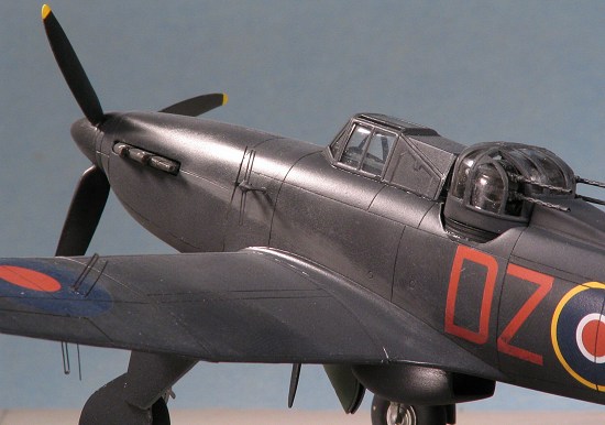
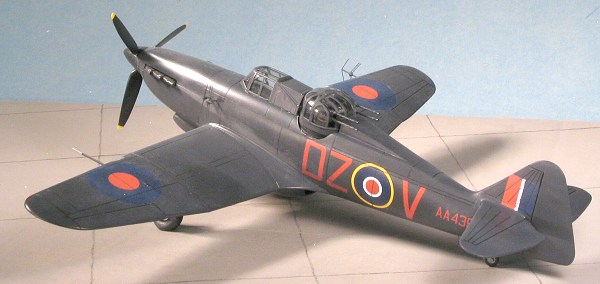
With that problem cured, I started putting on the decals. Nice thing about night fighters is that they don't have all those stencil markings. Not even underside roundels. Decals are superbly printed by Microscale and provided no problems at all to put in place. A dose of the Microscale system got them to snuggle down just fine. With all that solid color I had to do something to break things up a bit. With that in mind, I took my artist's pen and outlined most of the panel lines. The black ink doesn't jump out at you as it would with a lighter airplane and I think it turned out fairly well. Normally, I don't do this panel line darkening deal, but wanted to see what it looked like. It really turned out fairly well as it isn't the first thing that jumps out at you as it does on a lot of models I see so done at shows.
| FINAL CONSTRUCTION |
Unlike some other models, there
really wasn't much to the final construction on this one. Basically, I
glued in the exhaust and then figured out where the wing antennas were to
go (as I thought, they went where there was a roundel on the upper wing). I
drilled the upper holes and just continued through the bottom wing as well
so things would be properly aligned. The forward
 antenna on the wings needs
a larger hole than the back one. For the ones on the fuselage side, I
drilled holes just to have some sort of guide as to where these would go. I
then painted the wing tip lights using Vallejo transparent green and red
acrylics. I also removed the masking from the transparencies. I was
delighted to note that I could actually see the detail in the cockpit
through the rather thick plastic. This thickness also means that you can
install the landing light covers or the landing lights but not both. I
chose the covers. I had to sand them a teeny bit to get them to fit and
they are quite snug. I also took a couple of diameters of stainless steel
tubing to make the pitot tube.
antenna on the wings needs
a larger hole than the back one. For the ones on the fuselage side, I
drilled holes just to have some sort of guide as to where these would go. I
then painted the wing tip lights using Vallejo transparent green and red
acrylics. I also removed the masking from the transparencies. I was
delighted to note that I could actually see the detail in the cockpit
through the rather thick plastic. This thickness also means that you can
install the landing light covers or the landing lights but not both. I
chose the covers. I had to sand them a teeny bit to get them to fit and
they are quite snug. I also took a couple of diameters of stainless steel
tubing to make the pitot tube.
I next did the various antennas. It is a good idea to do these last as they are so easily damaged and bent. Once they were glued in place, I did the usual touch-up painting as the PE parts tend to shed paint as they are handled. I did a dirty thinner wash in the wheel wells, added some pastel exhaust stain using a darkish grey so that it would stand out against the background of the fuselage. The final steps were gluing on the prop and the turret. I was done.
| CONCLUSIONS |
Once again, a really fine model courtesy of Classic Airframes. I really enjoyed doing this one as there were a few challenges, but really, nothing beyond most modelers. Though I'd dreaded installing the radar antennas, it wasn't anywhere near as much effort as I'd originally thought. The key, I guess, is to work methodically and not get into a hurry. That is something I did throughout the entire build and after about a month of work, the end result is one that is most pleasing. I think that you'll be quite happy with it as well and can recommend this one for you to add to your collection.
December 2004
#1342 in a series
Copyright ModelingMadness.com. All rights reserved.
If you would like your product reviewed fairly and fairly quickly, please contact the editor or see other details in the Note to Contributors.