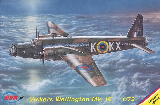
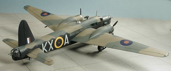
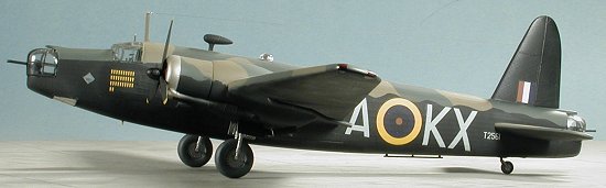
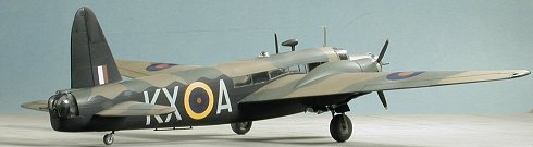
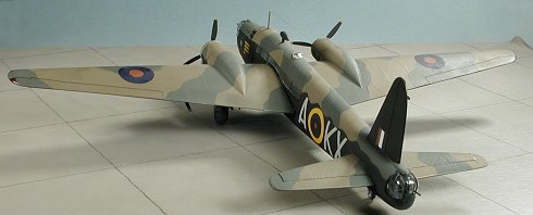
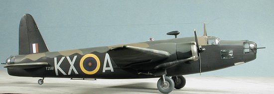
MPM 1/72 Wellington IC
|
KIT # |
72099 |
|
PRICE: |
$ |
|
DECALS: |
five aircraft |
|
REVIEWER: |
|
|
NOTES: |
|
BACKGROUND |
For a look at what is in the box and a brief history, please see the preview.
|
CONSTRUCTION |
As with most of my model building, I looked for subassemblies and started with them. This meant the wings, stabs and interior. For the wings, the first thing needed is to glue together the wheel wells. Once that was done, they were test fit. That brought out the need to do some sanding to the well join area. A few passes with a sanding stick were all that was needed. The join area was then flooded with Ambroid 'Pro Weld', my favorite 'hot' cement. The wells were then pressed down and the cement allowed to melt the plastic into place. If you are not using a cement such as this, you may want to consider it. It is water thin and bonds very well indeed.
Once that had dried, I cut away the plastic that had oozed out of the seams and dried. Then the upper wing was applied, or should I say I tried to apply it. On both sides, the wing would not fit flush as the wheel wells appear to be a bit too tall. Again, I grabbed my handy sanding stick and sanded the upper portion of the well until the wing would fit without any gaps. I found that by also sanding the edges, I was able to get it down far enough without worry about sanding a hole in the top of the wheel well.
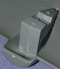 Wheel well installed |
 Gap caused by too tall a well |
 Well sanded down to fit. |
After that was done the upper wing was glued in place. While the fit was fine, I noticed on the first wing I did, that the trailing edge had a bit of a gap in it. This was filled with putty and later sanded smooth. On the other wing, I scraped the trailing edge of the wing and got a much better fit. It seems that while the actual trailing edge is nice and thin, just back from it a millimeter or so it is thicker. This thickness is what keeps the trailing edges from properly mating. I had similar things occur with the horizontal stabilizers. Not a disaster, but something that you should check and correct prior to gluing. Test fitting the fin/rudder, I found a very good fit without the gap.
I then turned my attention to the interior. Starting with the bulkhead, I glued on the two interior spaces that jutted out. There is no indication on the parts where they are to be glued, though the instructions do show the location. I made sure that all would properly fit by test fitting this part into a fuselage half before the glue had set. A more positive gluing area would be appreciated on the next kit as would a side view of the nose section with all the bits in their proper place. I next installed the right nose bulkhead items. Again, no positive location was given other than outlines shown in the instructions. None of the parts fit flush as the fuselage is curved and the lattice detailing keeps them above the surface so care is needed to attach them. Again, more positive locators for these parts would be appreciated in following kits. I also noted that some of the thicker parts had slight sink marks in them, but none were really that bad and easily filled.
 While building up the cockpit area, I noticed that the rudder
bar is too long and should be shortened if you want a good fit. Same with the
pilot' seat support. If left as is, the seat sits way to high. I ended up
removing most of the mounting peg. Once all
the interior bits were in place, it and both fuselage half interiors were
sprayed with RAF Interior Green using Testors Model Master enamels.
While building up the cockpit area, I noticed that the rudder
bar is too long and should be shortened if you want a good fit. Same with the
pilot' seat support. If left as is, the seat sits way to high. I ended up
removing most of the mounting peg. Once all
the interior bits were in place, it and both fuselage half interiors were
sprayed with RAF Interior Green using Testors Model Master enamels.
I then turned my attention to the turrets. The front and rear ones build the same but are slightly different in size so I marked an F for the forward one on the bottom of the turret to make sure I didn't get them mixed up. The gun mounts are shown as having one side as D23 and the other as D24. Well it doesn't work that way. Use both D23s for one mount and both D24s for the other. Again, no really positive locators for the parts so I decided to build one turret first to make sure there were no problems or if so, then they could be corrected on the other.
All of the plastic bits (sans guns) were glued to the turret
floor. I then removed all the clear bits for the turret and started cementing
them together as per the instructions. While doing this, I realized why I build
so few bombers. The clear parts for turrets just give me fits. This particular
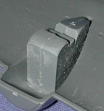
set is designed in a rather clever manner. There are two sides with a center
 section that fits between
them. A back piece will go on later. The design is quite good and offers
the rather unusual forward bulge that the turret has. It couldn't be done in one
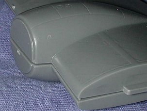
piece, that is for sure. Anyway, after butchering the gluing of the clear parts
and getting glue where it shouldn't be, I test fit the clear bits. They didn't
fit. I figure I may have gotten the gun mount parts too far forward and will see
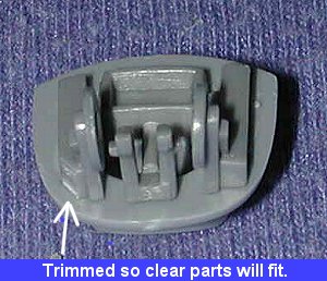
how the other turret goes. What I did have to do was trim the forward sections
as shown in the image to the right. The clear bits are rather thick so you'll
have to take that into account when doing the turrets.
section that fits between
them. A back piece will go on later. The design is quite good and offers
the rather unusual forward bulge that the turret has. It couldn't be done in one
piece, that is for sure. Anyway, after butchering the gluing of the clear parts
and getting glue where it shouldn't be, I test fit the clear bits. They didn't
fit. I figure I may have gotten the gun mount parts too far forward and will see
how the other turret goes. What I did have to do was trim the forward sections
as shown in the image to the right. The clear bits are rather thick so you'll
have to take that into account when doing the turrets.
After assembling the other turret (a job that went much smoother than the first), my attention was turned to the engines. The idea of gluing nine tiny cylinders onto a small engine block did not fill me with glee. I did manage to get them all assembled, but frankly, I'd much prefer the engine to be a single piece. Truly, I cannot see the reason for this exercise other than to increase the parts count. No way can I get things as well aligned as with a one-piece engine. Whining now over, I took the engine that I'd so carefully constructed and went to fit it into the cowling. Too big.........
Returning to the fuselage I painted all the interior parts, the wheel wells and the gun turrets RAF Interior green. I then picked out various boxes and bits in flat black and gave them a quick dry-brush. Now, this is contrary to the kit painting instructions in several areas. They state that most of the interior is in red brown with the lattice work painted aluminum. Sorry, but I'm not going to spend a lot of time doing this. It is a tedious job that is best left for others if they want absolute authenticity. For me, RAF Interior Green will do nicely, thank you.
When dry, I then started to install the fuselage transparencies. The fit is fairly good. The very long clear bits that go over the wing are the most difficult due to their length. Careful fitting will get them flush. I then noticed that something looked a bit odd. Checking many photos, I saw that all the pictures showed the lattice work prominently visible through the windows. This is not present on the kit bits. Perhaps a decal would be in order to simulate this as I'm sure that etching this on the clear parts is probably not possible. Be careful not to stress these parts too much. I did on a forward side window and the stress fractures are easy to see.
 With the transparencies in place, I glued
the fuselage. Fit is really quite good. There were a few places near the sprue
attachment points that needed filler, but overall it was a good deal. The
instructions show the turrets being installed at this time, but they will fit in
afterward and so were left off. I then masked the fuselage transparencies and
installed the horizontal stabilizers. Fit wasn't bad at all. There seems to be
no root fairing for the tail planes, so I guess this is normal for the type.
With the transparencies in place, I glued
the fuselage. Fit is really quite good. There were a few places near the sprue
attachment points that needed filler, but overall it was a good deal. The
instructions show the turrets being installed at this time, but they will fit in
afterward and so were left off. I then masked the fuselage transparencies and
installed the horizontal stabilizers. Fit wasn't bad at all. There seems to be
no root fairing for the tail planes, so I guess this is normal for the type.
I then went to glue on the wings. On both sides, I had to enlarge the fuselage slots to accept the wing tab. With no turrets installed, it was easy to blow out all the shavings that fell into the fuselage. The fit was really quite good. MPM has small wing roots that stick out from the side to allow for alignment of the wings to the fuselage. It would have been nicer to have had indentations in the fuselage for the wings to slot into, but that would have interfered with the interior detail work.
Attention was then turned to the rest of the fuselage transparencies. The lower bomb aimer's transparency was a tad too wide, so after it was installed, I sanded off the offending sections that jut out and polished them with finer and finer grades of sandpaper. Then it was on to the main transparency. At this time, I noticed that I'd forgotten to install in the instrument panel! Yikes! Getting this beast in place was not fun and not very well done. Take my word for it, you need to install this piece BEFORE gluing the fuselage halves together.
 The main canopy was a pretty tight fit. Some trimming was needed to get it in
place. Then you have the option of clamping it so it isn't too tall or too wide.
Your choice, as you can only do one of them. I chose the not too tall option and
when dry did some trimming on the sides. I figured that they'd jut out a bit
normally to allow the side windows to open. Anyway, that is my story and I'm
sticking to it!
The main canopy was a pretty tight fit. Some trimming was needed to get it in
place. Then you have the option of clamping it so it isn't too tall or too wide.
Your choice, as you can only do one of them. I chose the not too tall option and
when dry did some trimming on the sides. I figured that they'd jut out a bit
normally to allow the side windows to open. Anyway, that is my story and I'm
sticking to it!
It was then on to the engines. I've already mentioned the miserable separate cylinders thing. Fortunately, that will all be hidden behind the front cover, so no need to go nuts on the engine. The front cover seemed to have an attachment that was too small. I opened it up a bit more so that the small flange on the front of the engine would fit in there. This gave some positive gluing area. When dry, the cover was painted flat black.
Meanwhile, I glued the cowling front/exhaust collector onto the engine cowling. Fit is fairly good, but I had trouble getting it to be a perfect match. Next time, I'll file off the flange on the cowling and try a butt fit to see if the fit can be improved. When dry, the engines were inserted from the rear. The reference I used shows that the engine cover comes almost to the front of the cowling. There is no positive placement help in the cowling at all so you just have to fiddle with it until you get it where you think it should be. I did that and then glued the engine in place. That was followed by some superglue just to make sure nothing came adrift.
With the engines in the cowling, the cowlings were fit onto the nacelles. A touch of trimming was needed here, but the fit was quite good. You need to look at the construction drawings to properly align the engines. The single cowl panel line needs to be in a specific locale. Paying attention to this alignment will keep things looking good.
 The next step was to glue together the exhaust. Each side has a three piece
exhaust that is fiddly and there is no exact guide to show you how it fits. It
would be best if the exhaust were a single piece. That way there would be no
problems with alignment. There are other parts in the kit that are just as long
and just as complex so it is not beyond the abilities of the mold makers.
The next step was to glue together the exhaust. Each side has a three piece
exhaust that is fiddly and there is no exact guide to show you how it fits. It
would be best if the exhaust were a single piece. That way there would be no
problems with alignment. There are other parts in the kit that are just as long
and just as complex so it is not beyond the abilities of the mold makers.
While that was drying, I tackled the rear turret transparencies. Having made a mess of the front one, I went about this one a bit differently. Starting with the back piece, I glued the two side pieces to it and then to each other. When that was dry, the small insert for between the guns was glued in place. This worked out quite well and I suggest a similar approach when you do yours.
The glass parts were masked and it was time to do some more gluing. Starting with the front one, I glued the guns in place. Then I tried to fit the clear parts. Well, the guns were too close together and didn't fit through the slots worth a hoot. They eventually broke loose due to all the fiddling I did trying to get them to fit. Eventually, I was able to reglue them so that they protruded through the slots. Then I tried to install the turret in the nose. Despite all attempts at trimming and such, I couldn't get a good fit properly. The darn thing seemed too small. Taking the 'rear' clear bits, I test fit them into the rear. Too big! Trying to put them in the front....a perfect fit.
 Well this tells me one of two things. Either I misread the instructions
regarding which part numbers went where in regards to the turrets, or the
instructions have things backwards. With the parts off the sprue it is
impossible to tell, so a word of caution. Also, it seems as if the turret glass
needs to fit flush with the lip on the fuselage. That means that it doesn't
fit atop the turret base as I had assumed. Perhaps the base fits inside
the lower part of the turret greenhouse. The instructions are not very clear on
this. If that's the case, some trimming may be needed.
Well this tells me one of two things. Either I misread the instructions
regarding which part numbers went where in regards to the turrets, or the
instructions have things backwards. With the parts off the sprue it is
impossible to tell, so a word of caution. Also, it seems as if the turret glass
needs to fit flush with the lip on the fuselage. That means that it doesn't
fit atop the turret base as I had assumed. Perhaps the base fits inside
the lower part of the turret greenhouse. The instructions are not very clear on
this. If that's the case, some trimming may be needed.
What I did was to glue the base of each turret to the inside of the fuselage so that it was flush with the lip of the fuselage. Then I glued the turret to the fuselage and base at the same time. The fit was much better and looked as it should. There was some trouble getting the greenhouse over the guns and such so perhaps one should install these parts before the fuselage is glued together as the instructions show. Since the turrets don't rotate, it shouldn't be that much of a problem. I then masked off as much as I could and decided to start with some painting.
|
CAMOUFLAGE |
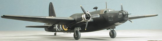
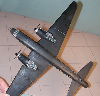
You can do your Wellington IC in any color you want as long as it is black on
the underside and dark green/dark earth on the upper surfaces. The black
(actually Night) is supposed to be a matte color. However, I decided to use a
gloss black. I had some gloss Tamiya acrylic sitting around not being used, so
chose that to paint the undersides first. It went on without any
 fuss at
all and covered quite well. I then masked some of it off to get ready for
the other colors. When I pulled off a section of tape to readjust it, off came a
lot of paint. GRR!! Now you know why I'd rather use enamels. I went over the
entire aircraft with tape to pull up any non-sticking paint. Then I repainted
the aircraft with gloss black enamel from the little square Testors
bottles.
fuss at
all and covered quite well. I then masked some of it off to get ready for
the other colors. When I pulled off a section of tape to readjust it, off came a
lot of paint. GRR!! Now you know why I'd rather use enamels. I went over the
entire aircraft with tape to pull up any non-sticking paint. Then I repainted
the aircraft with gloss black enamel from the little square Testors
bottles.
After that dried, the dark green (from Testors Model Master) was applied. Much masking later, the dark earth was shot, this time using Xtracolor. Fortunately, the Xtracolor dried very quickly and I was able to mask and paint the leading edges of the cowlings with light exhaust, another Alclad II color. The next day it was time to remove the masking and continue with adding some bits and pieces.
|
CONSTRUCTION CONTINUES |
Once all the masking was removed, I went to install the undercarriage. As
luck would have it, the main landing gear on my kit were too wide to fit into
the wheel well. Not sure just what the problem is on this as the edges of the
gear well are properly aligned with the opening in the nacelles. I fussed and
fidgeted until I got them crammed in there and then quickly doused them with
glue. I added an outer coating of superglue just to help hold them in place. The
retraction struts fit on their little posts just fine, but were too short and
too narrow to meet on the main gear just where they showed on the instruction
sheet. I placed them both in the same locale and hoped for the best. The tail
wheel strut mounting post was too wide for the too
 narrow tail wheel well. I
sanded on one side of it until I was able to get it to fit more or less centered
and then added glue and superglue to be sure it wouldn't move.
narrow tail wheel well. I
sanded on one side of it until I was able to get it to fit more or less centered
and then added glue and superglue to be sure it wouldn't move.
Among the other pieces that had to be added were the lower engine carb intakes (which were later painted black) and the exhaust. The engine exhaust pipes are three pieces that are butt joined together. Why this isn't done as a single construct is beyond me as it just needlessly adds to the chance of screwing something up. It also has to be constructed a specific way as it isn't just a straight pipe. There is no helpful drawing to show just exactly how this is to be aligned. Once the were built, they were painted and glued in place. There are two other long exhaust tubes that I'm not really sure just what they are, though I suspect fuel dump pipes. The instructions would have you paint them the same color as the exhaust, though that color is only listed by Humbrol number and there is no generic name given for it anywhere. These were glued onto the two spots that you can just make out on the underside of the wing.
The model was then able to stand on its gear and was given a coat of clear acrylic gloss in preparation for the decals.
|
DECALS |
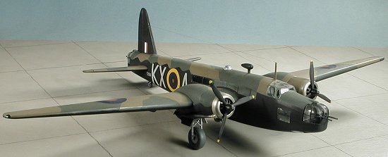
Having very little in the way of aftermarket decals, I used the kit decals and chose scheme C, one of the 311 Sq aircraft coded KX*A. The decals are made by Cartograph of Italy and are very well printed. The aircraft of the squadron in question all had large yellow surround fuselage roundels with the white blacked out. The decals appeared larger on the plane than they did in the placement drawings, but they fit well. There really is little to the markings other than roundels, codes and serial numbers as 311 Sq planes were rather non-descript at this time. There are no under wing markings as is typical for night bombers. However, they do the job and look very nice. I originally used Solvaset, but either my bottle is getting watered down or the decals are strong as they did not snuggle down as well as I'd have liked. A dose of Champ got their attention!
|
THE LAST BITS |
 With the decals now in place, it was time to add the final pieces. First were
the wheels. The main ones just barely fit so were glued in place. The tail wheel
just sort of fits in there and you have to glue the tire to the gear fork to get
it to hold. Moving to the gear doors, it would not be much of a surprise to say
that the forward ones don't fit well, and this is because of the too-wide main
gear legs that I had to sort of jam in there. A bit of trimming and they are
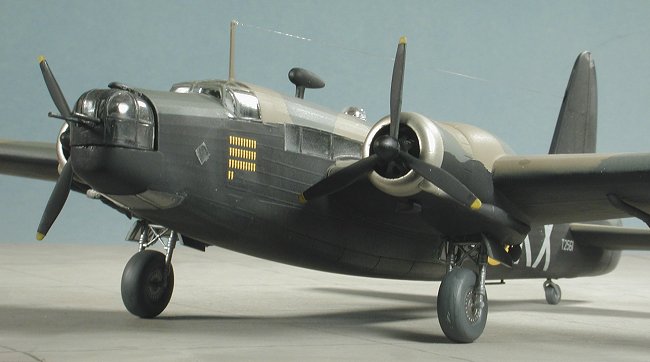
convincing enough. A 'towel rack' antenna was then glued to the underside.
With the decals now in place, it was time to add the final pieces. First were
the wheels. The main ones just barely fit so were glued in place. The tail wheel
just sort of fits in there and you have to glue the tire to the gear fork to get
it to hold. Moving to the gear doors, it would not be much of a surprise to say
that the forward ones don't fit well, and this is because of the too-wide main
gear legs that I had to sort of jam in there. A bit of trimming and they are
convincing enough. A 'towel rack' antenna was then glued to the underside.
Moving to the upper part of the plane, I drilled a hole to accept the upper direction finder 'football' antenna. The main antenna mast was just glued slightly behind the cockpit. It was then brush painted dark earth. The astrodome was also glued on at this time. Attention was now turned to the props. These were painted black with yellow tips. The spinners were also painted black and glued to the front of the props.
|
CONCLUSIONS |
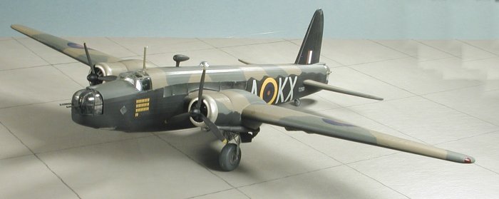
This kit is, indeed, a major step forward for MPM. They are serious about joining the 'big boys' and the Wellington is a positive move in that direction. I'd have to say, however, that they still have a bit to go before getting there. I had some fit problems to overcome, but in all fairness, a few may have been self induced. I also found the instructions a bit less than helpful in regards to the fitting of the turrets. If I had a gripe, it would be in the unnecessary complication of the engines and the exhaust. If parts cost money, then do us both a favor on the next one and make an effort to simplify some of these needlessly fussy constructs into a single piece. Overall, it is a very nice kit; one I'm glad I had the chance to build, and one that I'm sure will do well.
August 2002
Copyright ModelingMadness.com. All rights reserved.
If you would like your product reviewed fairly and fairly quickly, please contact the editor or see other details in the Note to Contributors.