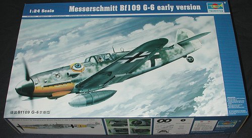
Trumpeter 1/24 Bf-109G-6
|
KIT # |
02407 |
|
PRICE: |
$110.00 MSRP |
|
DECALS: |
Two options |
|
REVIEWER: |
|
|
NOTES: |
Clear fuselage and control surfaces |
|
HISTORY |
I'll not go into this at all as I've pretty well covered this in a number of different reviews. However, I can go into some reason for buying this kit. First of all, I've always liked the 109 and am more than willing to build a model in just about any scale. Second, I knew that eventually I'd be getting this. Though I've not read any reviews on it, I have heard from others that it is basically well done and correct in most areas that it counts. For me that is fine as I'm not a rivet counter and 99% of other modelers wouldn't notice a minor glitch unless it was pointed out to them. Finally, I found one at a pretty good price so thought I'd go ahead and dive into it.
|
THE KIT |
 My first impression, after struggling to open the box, was that this is
much like the Hasegawa 1/32 109. Of course, it is equally probable that
there are only so many ways to do a 109 so many kits will have
similarities. After scoping out the many carefully bagged sprues, I thought
that this would end up being a very nice model when done. I'm not really
sure what benefit a clear fuselage and control surfaces would be and would
rather have taken a savings in cost than have them included. I'm also not
sure why there are two canopy sprues as I see no difference in the two.
My first impression, after struggling to open the box, was that this is
much like the Hasegawa 1/32 109. Of course, it is equally probable that
there are only so many ways to do a 109 so many kits will have
similarities. After scoping out the many carefully bagged sprues, I thought
that this would end up being a very nice model when done. I'm not really
sure what benefit a clear fuselage and control surfaces would be and would
rather have taken a savings in cost than have them included. I'm also not
sure why there are two canopy sprues as I see no difference in the two.
Instructions are quite complete and offer a very logical construction
sequence. I feel they don't have all the colors right and will attend to
the differences during building. I do have quite a few references for the
109 and find that the Model Art on the
 109G to be quite useful when
it comes to colors. In that edition are photos of a basically unrestored G
that is in Finland so will be using that one and a cockpit photo that I
have here on the website of a G interior from the NASM when it comes time
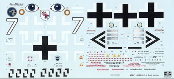
to do the cockpit. Aeromaster has done the decals and two options are
provided; one for White 7 from II./JG 51 and the other for Anton Hackl of
III./JG 11 (though no unit info in provided on the sheet). Both schemes are
not unique as they've been offered on many other aftermarket sheets. You
will note that the swastikas are split up for sale of the kit in squeamish
countries. Decal and color instructions are superbly done with a color
markings sheet that has a large listing on the back for Model Master
enamel/acrylic and Polly scale acrylic colors.
109G to be quite useful when
it comes to colors. In that edition are photos of a basically unrestored G
that is in Finland so will be using that one and a cockpit photo that I
have here on the website of a G interior from the NASM when it comes time
to do the cockpit. Aeromaster has done the decals and two options are
provided; one for White 7 from II./JG 51 and the other for Anton Hackl of
III./JG 11 (though no unit info in provided on the sheet). Both schemes are
not unique as they've been offered on many other aftermarket sheets. You
will note that the swastikas are split up for sale of the kit in squeamish
countries. Decal and color instructions are superbly done with a color
markings sheet that has a large listing on the back for Model Master
enamel/acrylic and Polly scale acrylic colors.
|
CONSTRUCTION |
I've gotten a lot of feedback regarding the desire to read
about on-going construction, so that is how I'm going to treat this
particular build. Yeah, not very original, but what the hey. Since it won't be a quick construct, this format will
work out quite well and allow me to build other models around it, so to
speak. The first thing I did was to read the instructions. On a kit of this
complexity, it is the best way to do things. It also allows me to see what
I can build in the way of subassemblies while other bits are drying or
being painted. I've always been a proponent of gluing as many bits that
will be the same color together at the same time. This makes painting
simpler and I've found that when one scrapes paint to glue two pieces
together, often one has to repaint the area anyway so it saves a step.
30 September
While that was drying, I glued the oil tank halves together, trapping a
small line in between them. Try as I might, I still broke this very fragile
line. A problem with softish plastic. The match between these two halves
was quite poor so much filler was slathered on. I also glued together the
supercharger halves. There is a bit of a seam on this as well. According to
drawings of the engine (and I used Aero Detail #5 on the 109G as a primary
reference), this seam will be nearly invisible, but I'm not taking any
chances. I then cleaned the seam from the large, oval induction piping.
So after a few hours of work, that is the
beginning as you can see in the photos of the day's effort. I'll do at
least one photo for each day that I work on this to show you how things are
progressing. 1 October
I glued together the two small side tanks which I can
only assume are oil overflow tanks. These had filler applied as did the
supercharger. I then turned my attention to starting on the interior. The
floor of the interior is
Then I decided to see about these wiring harnesses that are provided. They
are made out of some sort of very flexible and soft plastic. Heaven only
knows how to paint these things and I'm not going to try. Anyway, they have
to fit into the spark plug holes (2 per cylinder) so I figured I'd test fit
them to see how it is done. Before you write to tell me there are only five
sets of plug wires, I checked the reference and this is exactly how it
looks! I drilled out the holes with a #75 drill bit and found that was too
small. I went up a few sizes to a #72 and that was the ticket. I then
carefully stuck each 'wire' into the appropriate hole with a pair of
tweezers. They hold rather well and it seems that it won't be the hassle I
thought it would initially be. Sometimes taking the time for test run will
save your sanity later! Results of today's work shown to the right.
2 October
The trim wheel mount was installed as were parts for the rudder pedals.
This consisted of a 'D' shaped item on the floor, the pedal mounts and the
pedals themselves. Thanks to the slight mold misalignment, these bits need
to be cleaned up prior to gluing. I painted the back of the instrument
panel film with Vallejo acrylic white so the instruments will stand out.
When most of the interior parts are painted, I'll attach this to the back
of the panel and then the whole construct to the three-part panel shield
that is in the lower left. Finally, I glued together half of the exhaust
stacks. These all needed flash on the inside removed and there will be a
seam on one side of each of the exhaust as you can see near the tab on the
lower exhaust. This will need filled. What is missing is the normal seam
along the center of each exhaust stack. These were welded and the weld seam
is quite noticeable on the real aircraft. If you want absolute accuracy,
then you might want to run a section of stretched sprue on the inside and
outside middle of each stack.
So far things are going fairly well with no disasters as of yet! The pile
of bits is increasing and the sprues are getting less populated!
3 October.
Today most of my work was in regard to the cockpit. First off, I
sanded off the final ejector pin mark on the cockpit floor and installed
the trim wheels. Then I installed several items in the cockpit itself. On
the left sidewall, these were the throttle quadrant with throttle and
mixture control, the canopy lock mechanism, the motor for the trim wheels
(this assembly happens to be missing the chain, something that is quite
prominent when you peer into the cockpit of a 109) and the vent control. On
the right side I installed the voltage regulator, a set of auxiliary
instruments, and a handle/control whose use I'm not sure of. The small
instrument cluster is too far forward and the handle of the control unit
needs to angle more toward the center of the cockpit. No way could a pilot
reach that handle as the kit has it. There is also a total lack of wiring
anywhere in the cockpit. In those days, wire bundles were easily seen as
there was no cockpit insulation padding as we have nowadays.
I should also mention that there are easily seen ejector pin marks inside
the supercharger intake which I sanded as best I could. Those in the
cockpit that I thought would cause a problem I had to scrape away with my
scalpel as I couldn't get sandpaper in there. Others are covered or will be
covered by bits or otherwise difficult to see. I'll now take a number of
bits to the paint shop to have some color added to them before I continue
construction. I'll repeat that the kit color information is suspect at
best. Yes, the cockpit is RLM 66, but not EVERYTHING in there is this
color! If you don't have a good book for research, then use the
109G-6 cockpit photo I've got
here on the website and print it out. Though it only shows the right side,
it is quite useful. You can see some of the problems I've mentioned just by
looking at this photo that I took at the Smithsonian back in 1981.
4 October
Once that was
done, the rest was detail painting. I used a 5/0 brush for this. First of
all, I painted all the bits and pieces that were to be black with Floquil
Engine Black. That not only included a bunch of boxes but most of the
instrument housings. This took time. Various knobs and buttons were painted
with drops of white using Vallejo acrylic colors. This is because I was
putting red or yellow atop them and they needed the white background. Once
that was dry, I did the red and yellow trim, again using Vallejo acrylics.
There are two
areas that took extra work. One was the instrument panel. In addition to
doing the various buttons and stuff, the rim of several instruments needed
a color other than black. Now you'll find examples of indicators without
these additional colors or with them in different places. My reference
showed a number of different options, but I took the more colorful ones.
For the brown, I used Tamiya Hull Red which seemed a good match.
Yet to be done is to add some
more bits to the cockpit and then give it a wash and dry brushing to
enhance what little detail there is. That is later.
5
October
Other stuff I did was to glue together six more exhaust stacks and apply
filler on the other six that had already dried. I also drilled out the
holes in the upper wing to install the bulges. These will leave
Finally, I added more pieces to the engine after making sure there would be
no interference with the pieces I've yet to install. I glued on the small
steam extractors, the valve covers and the oil lines to the valve covers.
All these pieces needed cleanup of some sort. I'll be painting some of
these bits and pieces in preparation for more construction tomorrow. You
can see the evening's work (minus the exhaust) in the above image. If it
seems like I'm going pretty slow, well, I am. There is no rush to finish so
I'm taking my time with this one. I'm sure that there are modelers out
there who'd have this puppy nearly done by now, but I'm not one of them!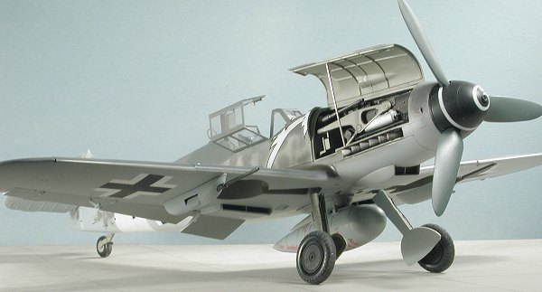 After perusing the instructions, it seemed as if this was basically going
to be a series of 'mini-kits' that will be put together into a final
product. First of those mini-kits is the engine. I started to assemble the
engine by putting together the main pieces of the engine block. Now I've
noticed that nearly all the parts of any size have ejector pin marks;
either shallow indentations or raised bumps. Most parts have some flash
that will need to be cleaned up as well. I then added the air valve on the
crankcase housing and the prop reduction gear housing along with the prop
shaft. I then filed and filled in the seams that I found on the front and
back of the block. I also glued together the magnetic generator (or what
we'd call a magneto) . This isn't the easiest bit to get right. There are
two semi-pyramid shapes that fit on there. They should have some 'dihedral'
on them when finished and the flat bits are on the bottom. Yeah, I'm not
being very lucid on this, but once you start building it, you'll see what I
mean. I also glued together the rear accessory housing.
After perusing the instructions, it seemed as if this was basically going
to be a series of 'mini-kits' that will be put together into a final
product. First of those mini-kits is the engine. I started to assemble the
engine by putting together the main pieces of the engine block. Now I've
noticed that nearly all the parts of any size have ejector pin marks;
either shallow indentations or raised bumps. Most parts have some flash
that will need to be cleaned up as well. I then added the air valve on the
crankcase housing and the prop reduction gear housing along with the prop
shaft. I then filed and filled in the seams that I found on the front and
back of the block. I also glued together the magnetic generator (or what
we'd call a magneto) . This isn't the easiest bit to get right. There are
two semi-pyramid shapes that fit on there. They should have some 'dihedral'
on them when finished and the flat bits are on the bottom. Yeah, I'm not
being very lucid on this, but once you start building it, you'll see what I
mean. I also glued together the rear accessory housing. 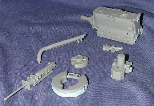 Moving on to the next
mini-kit, the engine mounted cannon. There are eight pieces to this which
consist of the gun body and the mount section. I first cleaned up all the
seams. It appears that there was some mold mis-match on this particular
sprue and while not really bad, it is something that will have to be taken
into account. I attached all the bits to the gun itself and then drilled
out the barrel. It isn't as detailed as the photos, but since it will
basically be hidden after construction, it will do nicely. The mount and
recoil section is a bit messy to glue together. I'm not sure if the various
seams on the bottom of the mount should be dealt with as it may well be
totally invisible once done. Test fitting when I get to that stage will see
how things go.
Moving on to the next
mini-kit, the engine mounted cannon. There are eight pieces to this which
consist of the gun body and the mount section. I first cleaned up all the
seams. It appears that there was some mold mis-match on this particular
sprue and while not really bad, it is something that will have to be taken
into account. I attached all the bits to the gun itself and then drilled
out the barrel. It isn't as detailed as the photos, but since it will
basically be hidden after construction, it will do nicely. The mount and
recoil section is a bit messy to glue together. I'm not sure if the various
seams on the bottom of the mount should be dealt with as it may well be
totally invisible once done. Test fitting when I get to that stage will see
how things go. 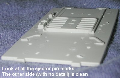 Today was a day for doing
other things beside model building so the output isn't as great as I'd
like. I sanded off the filler on the engine block, oil tanks and accessory
housing. The accessory housing was glued in place to the rear of the engine
and atop it went the magneto. You really need to test fit the cannon while
doing this as there is no lower tab to hold the housing. I discovered while
doing this, that you'll never see the cannon tip. However, when those
judges stick their rectal flashlights in the spinner hole, they'll see a
drilled out barrel! While that was drying, I build up the cowl machine
guns. The barrels on these are not totally circular and are actually a bit
flat. The tips of the barrels are also off-set to one side. Not exactly
great!
Today was a day for doing
other things beside model building so the output isn't as great as I'd
like. I sanded off the filler on the engine block, oil tanks and accessory
housing. The accessory housing was glued in place to the rear of the engine
and atop it went the magneto. You really need to test fit the cannon while
doing this as there is no lower tab to hold the housing. I discovered while
doing this, that you'll never see the cannon tip. However, when those
judges stick their rectal flashlights in the spinner hole, they'll see a
drilled out barrel! While that was drying, I build up the cowl machine
guns. The barrels on these are not totally circular and are actually a bit
flat. The tips of the barrels are also off-set to one side. Not exactly
great!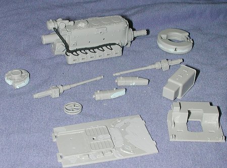 rife
with ejector pin marks; at least 13 of them. Some were sanded and the
others filled. Same with the firewall section which had a piece glued on
it. I also glued together the trim wheels and the engine cover.
rife
with ejector pin marks; at least 13 of them. Some were sanded and the
others filled. Same with the firewall section which had a piece glued on
it. I also glued together the trim wheels and the engine cover.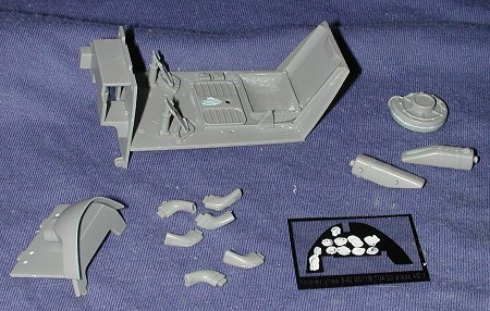 Since I had many things to do
during the day, I only had an hour or so to work on the kit. However, I did
manage to get several things accomplished. First off, I sanded the parts
where I applied filler yesterday, which were the supercharger, cockpit
floor and the small side tanks (upper left). I also went to work on the
cockpit some and though most of the ejector pin marks were filled on the
first run, one was stubborn and had to be refilled. Since most of the floor
was clear, I glued in the seat, seatback and firewall. The seat back had
pin marks on the side that were sanded down. The seat itself has two
ejector pin marks and it had a ridge of built-up plastic on the inner seat
sides that I scraped down as much as I could.
Since I had many things to do
during the day, I only had an hour or so to work on the kit. However, I did
manage to get several things accomplished. First off, I sanded the parts
where I applied filler yesterday, which were the supercharger, cockpit
floor and the small side tanks (upper left). I also went to work on the
cockpit some and though most of the ejector pin marks were filled on the
first run, one was stubborn and had to be refilled. Since most of the floor
was clear, I glued in the seat, seatback and firewall. The seat back had
pin marks on the side that were sanded down. The seat itself has two
ejector pin marks and it had a ridge of built-up plastic on the inner seat
sides that I scraped down as much as I could. 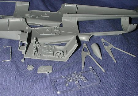 I left off the radio panel,
fuel line and oxygen regulator. The fuel line needs painted yellow, the
oxygen regulator blue (though some were black with a blue face), and I
can't install the radio as the fuel line should be installed first. At
least I think that is how it goes. We'll see tomorrow. I also attached some
handles to the clear instrument panel face (why it is clear is beyond me).
I also removed and cleaned up the engine mounts and glued together the
supercharger intake. This intake should have a seam running down it like
the exhaust as it was also a welded unit. Again, a piece of stretched sprue
will fix this for those who want to install it. I'm not sure if I'm going
to do it or not at this moment.
I left off the radio panel,
fuel line and oxygen regulator. The fuel line needs painted yellow, the
oxygen regulator blue (though some were black with a blue face), and I
can't install the radio as the fuel line should be installed first. At
least I think that is how it goes. We'll see tomorrow. I also attached some
handles to the clear instrument panel face (why it is clear is beyond me).
I also removed and cleaned up the engine mounts and glued together the
supercharger intake. This intake should have a seam running down it like
the exhaust as it was also a welded unit. Again, a piece of stretched sprue
will fix this for those who want to install it. I'm not sure if I'm going
to do it or not at this moment. 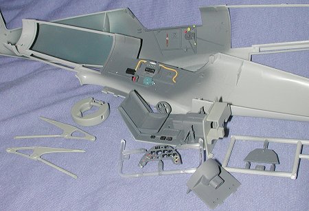 Today was spent painting. I
first painted all but the oil tank, engine mounts, fuel line, and oxygen
regulator RLM 66 using Testors Modelmaster enamel. The engine mount and oil
tank were painted RLM 02, also with Modelmaster. The regulator was painted
RLM 24 using Xtracolor enamel (because I had it) and the fuel line was
first painted white and then yellow. I also did the firewall of the cockpit
section in RLM 02 to match the area that it would be attached to. All of
the day's efforts are shown to the left.
Today was spent painting. I
first painted all but the oil tank, engine mounts, fuel line, and oxygen
regulator RLM 66 using Testors Modelmaster enamel. The engine mount and oil
tank were painted RLM 02, also with Modelmaster. The regulator was painted
RLM 24 using Xtracolor enamel (because I had it) and the fuel line was
first painted white and then yellow. I also did the firewall of the cockpit
section in RLM 02 to match the area that it would be attached to. All of
the day's efforts are shown to the left. 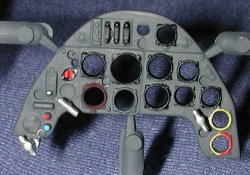
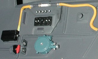 The other area that needed
special attention was the right cockpit sidewall. First of all, the aux
instrument panel needed something. I painted the face area white and when
dry, used some Reheat instrument decals. Some small 1/48 ones seemed to fit
well. They are not 100% correct, but look the part. Secondly the fuel line.
There is a clear piece in the center of it to show the pilot if fuel is
present or flowing. I could have cut the line and inserted a piece of clear
sprue. It is easy enough to do, but I did want to build this kit OOB as I
figure most modelers will be doing the same. My only other option was to
paint it silver or white. Since I was using silver for the clamps attaching
the rubber hose on either side, I chose white and it works rather well. The
lack of wiring and other plumbing does give the interior a rather bare
look. I'm sure that the aftermarket cockpits that are to come will take
care of these missing details!
The other area that needed
special attention was the right cockpit sidewall. First of all, the aux
instrument panel needed something. I painted the face area white and when
dry, used some Reheat instrument decals. Some small 1/48 ones seemed to fit
well. They are not 100% correct, but look the part. Secondly the fuel line.
There is a clear piece in the center of it to show the pilot if fuel is
present or flowing. I could have cut the line and inserted a piece of clear
sprue. It is easy enough to do, but I did want to build this kit OOB as I
figure most modelers will be doing the same. My only other option was to
paint it silver or white. Since I was using silver for the clamps attaching
the rubber hose on either side, I chose white and it works rather well. The
lack of wiring and other plumbing does give the interior a rather bare
look. I'm sure that the aftermarket cockpits that are to come will take
care of these missing details!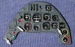 Sunday
is NASCAR day for this kid so I usually spend the day vegging out in front
of the TV watching the show. However, I did manage to spend an hour or so
on a few things. First off, I attached the clear instrument film behind the
instrument panel. Now the panel is really way too thick as the instruments
are in there pretty deep. I may try to fill in the instrument faces with
clear paint, but it may make more of a mess than it is worth. The problem
with sanding down the back of the instrument panel is that if one makes it
too thin, the handles and the gun sight may not have a good hold when
installed. Anyway, the end result is quite pleasing. One MUST paint the
back of the instrument film white or you won't see a thing.
Sunday
is NASCAR day for this kid so I usually spend the day vegging out in front
of the TV watching the show. However, I did manage to spend an hour or so
on a few things. First off, I attached the clear instrument film behind the
instrument panel. Now the panel is really way too thick as the instruments
are in there pretty deep. I may try to fill in the instrument faces with
clear paint, but it may make more of a mess than it is worth. The problem
with sanding down the back of the instrument panel is that if one makes it
too thin, the handles and the gun sight may not have a good hold when
installed. Anyway, the end result is quite pleasing. One MUST paint the
back of the instrument film white or you won't see a thing.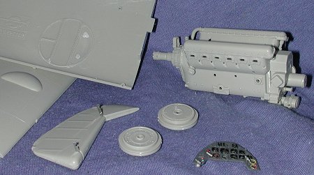 unsightly holes on the other
side and can be seen in the wheel well. I filled these holes with Mr.
Surfacer 500 and will sand them smooth when it has cured. I also glued the
wheel halves together. Now you must make sure you get the right wheels as
they are different on the G-2. At this time, I also attached the hinge
mechanism to the rudder. It is quite simple to do. One merely cuts the
etched hinges (use scissors as it is too much for a knife blade) and then
picks the proper length rod to go inside it. If you are metric stupid as am
I, then there are two lengths of rod, a short and a long. The short one
goes in the rudder. Simply place it in there and glue the rudder halves
together. This will be the same for the ailerons, flaps and elevators.
unsightly holes on the other
side and can be seen in the wheel well. I filled these holes with Mr.
Surfacer 500 and will sand them smooth when it has cured. I also glued the
wheel halves together. Now you must make sure you get the right wheels as
they are different on the G-2. At this time, I also attached the hinge
mechanism to the rudder. It is quite simple to do. One merely cuts the
etched hinges (use scissors as it is too much for a knife blade) and then
picks the proper length rod to go inside it. If you are metric stupid as am
I, then there are two lengths of rod, a short and a long. The short one
goes in the rudder. Simply place it in there and glue the rudder halves
together. This will be the same for the ailerons, flaps and elevators.