Tarangus 1/48 A32A Lansen
The Saab 32 Lansen (meaningthe Lance) was a two-seat, high transsonic attack aircraft produced by SAAB from 1955 to 1960 for the Swedish Air Force (Flygvapnet). During its long operational life, the Saab 32 also served as a fighter, reconnaissance, electronic warfare and a target-tug aircraft.
 When the A 32A entered service they replaced the last piston-powered SAAB B 18 bomber. Soon after entering squadron service, the J 32 Lansen broke the sound barrier on 25 October 1953 when a production aircraft exceeded Mach 1 in a shallow dive. The J 32 carried four 30 mm ADEN cannons while the A 32 ("A" stands for attack) had an armament of four 20 mm Bofors m/49 cannon hidden under flaps in the nose and the Rb 04C anti-ship missile, one of the earliest of its type in western service. The Lansen normally was fitted with two missiles but it could also carry an additional missile. Its main role was to prevent any Soviet invasion across Sweden's extensive coastline.
One planned use of the A 32A was to deliver nuclear warheads or chemical weapons. Sweden had an active nuclear weapons program during the 1950s and 1960s, but no weapons were ever produced.
The A 32 Lansen was Sweden's last purpose-built attack aircraft. Throughout the Cold War years, the Lansen distinguished itself with a solid if unspectacular career; Swedish pilots often described it as pleasant to fly. Gradually being replaced by more modern types, the Saab 32 soldiered on into the late 1990s. Two still remain operational with the sole task of taking high altitude air samples for research purposes in collaboration with the Swedish Radiation Safety Authority. One of those has been used to collect volcanic ash samples in April and May 2010.
Looking very much like an MPM designed kit, the molding is engraved and a tad on the soft side when compared to main line injection molded kits. There are ejector towers in several of the large parts that will need to be removed prior to construction. All of the sprues were packaged in a single zip bag with about a half dozen parts freed from their sprues. The clear bits are well 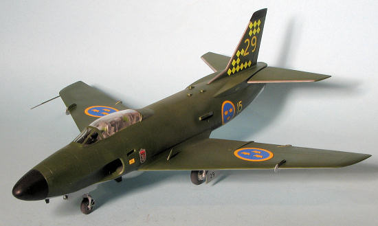 done, though perhaps a tad thick. It is designed to be modeled in the closed position as there is no extension jack or inner canopy detail. Resin is used for the two seats. There is no photo etch and no belt detail on the seats.
The cockpit is fairly well appointed with the aforementioned seats, control sticks and instrument panels. There is raised detail on the side consoles. The instrument panels have indentations where the instruments should go. There is no instrument panel decal so one is on their own in this regard. No sidewall detail is provided. There are actually two cockpit assemblies which are joined in the fuselage. The forward cockpit includes the roof of the nose gear well which has the separate side pieces joined together to complete the well.
Intake trunks are fairly long, though without blanking plates. This may not be needed as there is a compressor face for the inside of the afterburner so there should be no see through situation. There are a myriad of scoops for the upper fuselage that are separate pieces. The nose and main gear are nicely molded. The main gear well goes in the lower wing. Despite a low wing design, the lower wing is two pieces that have an overlapping join. The upper wing halves join to that before installation on the fuselage. Since this is the attack version, lower wing pylons are provided, each of which looks to be slightly different in design so one needs to pay attention during construction. There is an optional outer pylon. No weapons are provided, which seem to me to be a major omission. Also optional is a belly fuel tank.
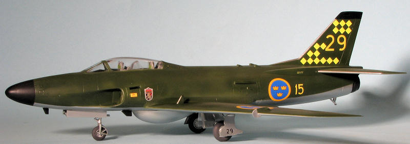
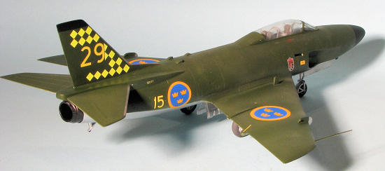
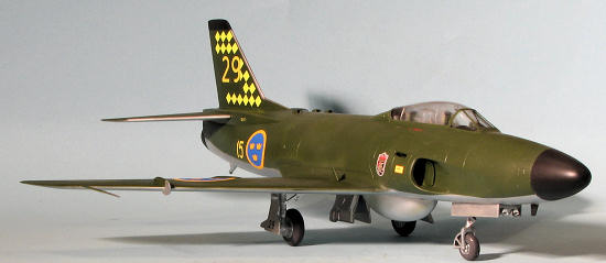 Markings are for two aircraft. one in the box art plane which is a restored aircraft from F17 in the standard Olive over unpainted metal. This aircraft uses the larger insignia. The other is from F15 and has the daglo yellow squares as used during an exercise in 1968. The decal sheet is very nicely done and designed for other versions as there are markings not used on this kit.
Instructions are very well printed and provide not only small alignment drawings, but an excellent data placement guide. All of the color information is generic, which is normally not an issue. The instructions do offer several suggestions to replicate the Swedish Olive Green 325 including FS 34079, Humbrol 116 and Tamiya XF-61. I should also mention that no nose weight information is provided. I would stick something in there just in case.
As is my wont, I started looking for subassemblies to put together and found quite a few. The tail pipe, horizontal stabilizers, main wheels, and the nose gear well were first on my list. Now I should start off this section by saying that I found the fit to be fair. The closest comparison I can make of this kit is of one of the older Czech Model kits such as the Skyknight. The parts are all t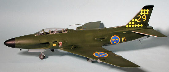 here, the detail is fairly good and every single piece will need to be cleaned up and test fit prior to applying cement. Even then, some parts, like the nose gear well, need to be assembled at one time so that the bits can be moved around to get the best fit before the cement cures.
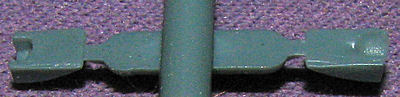
I also found it useful to prepaint as many parts as possible. For instance, the cockpits and interior side wall was painted with Tru-color's Union Pacific Light Grey, which is a pretty good match for FS 36231, Dark Gull Grey. The seats were given a coat of another Tru-color paint, NYC Grey, which is a slightly lighter shade and perhaps a close match for FS 36118. I also used their Aluminum for the wheel wells, inside of the intakes and the inner gear doors. The intakes have a splitter plate that goes inside them. Unfortunately for me, the intake sections had broken away during shipping and it took a lot of test fitting to figure out which was which. In the end, however you come to a decision, the splitter plate will have the straight part of it down with the curved bit in the upper intake. The intake section has ejector towers that will have to be removed. The fit of these intakes is dodgy so just get it to fit and that should work OK. There is no blanking plate for them so you may wish to make one.
I then moved to the wings and after cutting off and sanding down the ejector towers, I installed the main gear well into one lower wing half. I then attached the upper wing in that half. When dry, I glued the gear well into the lower wing half, not cementing the seam between the lower wings at this time. I felt it would make installing the wing easier to have the additional play room.
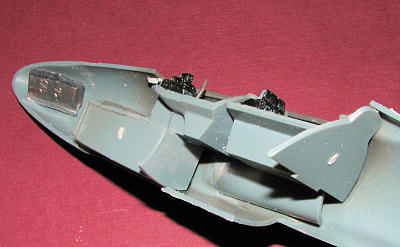 Next, the interior parts were tackled, but I first had to install the intakes. These were not a very precise fit, but after some fiddling, I was able to get them installed. The interior bits had the ejector towers removed from the floor with a grinding tool and then had the instrument panels installed. I test fit these two assemblies several times before finally gluing them in place. I am not sure why the cockpits had to be separate pieces. I would think that a two place tub would have been a better fit. At this time the exhaust pieces were glued together, had the nozzle seams filled and sanded and were then glue in place. I added weight to the nose as I was not sure if it was needed. It was and were I to do it again I would add a bit more as the model ended up being only slightly nose heavy.
Once all these bit were in and dry, I glued the fuselage halves together. I had to do this in sections as the fit is not the best. Fortunately the plastic is fairly soft as I had some issues getting the rear fuselage sections all the way together and found that if it lined up on the top it did not on the bottom, producing a step between the halves that required extra attention. The plastic just above the exhaust will just not come closed as there was not enough plastic molded there. The choice is a lot of fussing and sanding with insertion of plastic card to close the gap or leave it be. I chose the latter.
After getting the fuselage filled and sanded, I attached the wings. Fit here also required considerable trimming to get the parts to match up. This was particularly needed in the front as much sanding, filing and fitting was needed prior to applying glue. It was good that I decided earlier not to really glue the two wing halves together as once the wings were in place, there was a pretty good gap between them. A lot more sanding and filling was needed to get a smooth transition on the bottom.
 Once I was satisfied with the wings, I turned to the small scoops on the upper rear fuselage. These separate items needed work even before removing them from the sprue. One was completely filled with a blob of plastic while the others benefitted from some additional grinding to increase the size of the opening. I have to say that doing a kit like this is made so much easier with a low speed micro grinder. I got mine many years ago along with a selection of bits and I am so glad I did. A Dremel tends to run too fast even on its lowest speed and has too much torque compared to a small 3 volt battery powered one that you can basically stop with your fingers. Once those were in, I turned my attention to the cockpit once again.
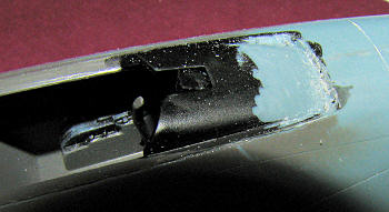 First thing was to install the anti-glare panel. This needed to be trimmed on the front to get the tongue to fit under the nose section. Then I test fit the windscreen. Man, what a poor fit. A lot more work with the grinder was needed to get to where the windscreen would not be raised high in the air on the front. While there was room to grind a bit on the front of the windscreen, most of the grinding was done on the front half of the anti-glare panel with considerable plastic removed in the process. With that done, the windscreen was glu
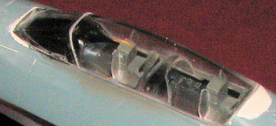 ed in place. Then the canopy section was installed. Well, it did not fit as it was too long. In this case, I did most of the plastic removal on the back area of the fuselage where the canopy fit, though a bit was also removed from the front and rear of the canopy itself. Once that was done, the resin seats were painted and removed from the resin pour stubs. These are the best detailed parts of the kit, though lacking in any sort of harness, which would have been a nice addition to what is an expensive kit. These have little clear 'ears' that attach to the side of the seat. Super glue was used and the inevitable frosting scraped away once dry. They are a tad oversize so needed some trimming to get the canopy to close over them. They were then glued into the cockpit.
This was followed by the rear seater's blast shield. When the canopy was glued in place, there was a pretty good size step behind it. This and the seams on the windscreen were filled and sanded smooth. The rear one took several applications.
Next step was the landing gear. These required considerable clean-up prior to painting and installation. For the main gear, the retraction struts do not fit anywhere near the assigned spot in the well due to interference with a cutout on the lower wing so that was glued as close as I could get to the proper location. The nose gear had one of the m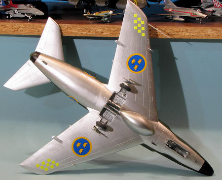 ounting posts broken during shipment so after repair, that was glued in place. The long retraction strut molded on the gear leg is weak to the max and broke away from handling while removing the strut from the sprue. It was glued in place and fitted as best as I could. Then it was all set aside to dry.
I next drilled out the holes for the various antennas. The lower nose one is shown in one place in the instructions and another in the four view drawings. A look at photos on the 'net helped clear that up. I should mention at this time that there are a set of strakes on the sprues that are not shown in the instructions. Apparently some aircraft had these and they hung vertically from just alongside the rear of the nose gear doors. I decided not to use them as one had a piece chipped from the end and I did not feel like repairing it. There was another part on the sprues that went unidentified as to just where it might have gone.
At this time, I went to attach the inner main gear doors. This will try your patience as there is no attachment spot and the doors are a bit smaller than the opening in which they must gap. I ended up attaching one end with super glue and hitting it with accelerator before building a super glue bridge to the other side of the opening. Not pretty. The outer gear doors, however, fit fairly well with no trauma. I then glued on the belly tank. I was initially not going to use this, but found that it was frequently carried. Nose gear doors had the landing lights glued in place and were then attached. The canopy and windscreen were masked and it was time for more paint.
The kit instructions call for FS 34079 Dark Green so that is what I used on the upper surfaces. The lower surfaces, including the gear well and everything else, was painted with Tru-Color Aluminum. This stuff is great and provides a very convincing appearance. It does, however, need an undercoat or it has a tendency to peel up if the tape you are using to mask over it is too sticky. I did first paint the aluminum and then the dark green, which was Testors Model Master enamel. These aircraft tend to look a bit 'patchy' after a while so I tried to simulate that in the green application. The nose and fin areas were then masked off and black was painted on those areas. There was actually quite a bit of back and forth on this as there are some tricky areas, like the intakes, to mask properly. I even b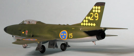 rush painted some of the dark green to take care of minor overspray. You cannot brush paint the Tru-Color on anything large and flat, though it does work well for pitot tube ends and such.
As I had pretty much all of the airframe painted and assembled, I gave it a couple of coats of Pledge (Future) to get ready for the decals. Looking at the decal placement guide, I realized I forgot to paint the leading edge of the stabs and fin with Aluminum. This was masked and those areas painted. I chose the more flamboyant of the two markings schemes for this one with the da-glo yellow squares and the larger insignia rather than the museum aircraft.
The decal sheet has markings for future Lansens as well as this one and there are A and B markings. No indication as to which is used on this kit, but looking at photos, I noticed that these were mostly the black ones. The decals are superb. They are super thin and quite opaque. One has to be very careful in application due to their thinness. I used Microsol, my weakest setting solution with good effect. It was time consuming as I only do a few markings before letting them dry and moving on to more. As a result, it took several days.
Once all that was done, the airframe was given a coat of clear matte on the dark green bits and the radomes. I glued the wheels in place. They all needed their attachment holes drilled out. I did more touch-up painting and then removed the masks. The final step was to install some MV Products #29 lenses into the landing lights. For some reason, the kit leaves these areas open as not even clear plastic lenses were provided. After that, I was essentially done.
This is the sort of kit that one builds because one really wants the subject. The general fit of parts is not the best, the plastic is a bit soft for some parts and the kit is missing things I would have thought would be included. By this, I mean there should be weapons, as Swedish bombs and rockets do not come readily to hand. The kit should at least have the guns scribed on the 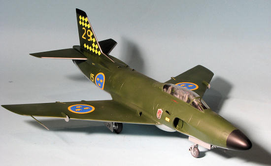 plastic, but they are not. I also found that the quality of the detail was not the same as what is shown in the instructions. The seats, being resin, were very nicely molded and the exterior detailing was well done, just things like control sticks, instrument panels, landing gear, for instance, were rather crude.
Now I realize that short run kits are not perfect, but it seems as if the company was in a hurry to get things into production and did not properly oversee the development of the kit. This lack of QA will undoubtedly hurt future sales unless Tarangus gets more involved. I also found the markings guide to be a bit vague regarding the use of A or B lettered markings and the instructions, though well drawn, were also a bit vague at times.
While I enjoy challenges like this, there are folks who do not and want something that does not require a relatively high degree of modeling skill to finish. Those who have experience building things like the old Czech Model Skynight or most Classic Airframes kits will be able to get through this one without any major issues. Those with lesser modeling skill will find this one frustrating.
http://en.wikipedia.org/wiki/Saab_a32
July 2012
Copyright ModelingMadness.com. All rights reserved. No reproduction in
any form without express permission from the editor.
If you would like your product reviewed fairly and fairly quickly, please contact the editor or see other details in the Note toContributors.
Back to the Main Page
Back to the Review Index Page 2025