| KIT #: | 02875 |
| PRICE: | $31.95 SRP |
| DECALS: | Two options |
| REVIEWER: | Scott Van Aken |
| NOTES: | Easy conversion |
| HISTORY |
The de Havilland DH.100 Vampire was a British jet fighter commissioned by the Royal Air Force during the Second World War. Following the Gloster Meteor, it was the second jet fighter to enter service with the RAF. Although it arrived too late to see combat during the war, the Vampire served with front line RAF squadrons until 1953 and continued in use as a trainer until 1966, although generally the RAF relegated the Vampire to advanced training roles in the mid-1950s and the type was generally out of RAF service by the end of the 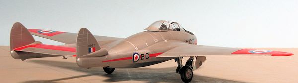 decade. The Vampire also served with many air forces worldwide, setting aviation firsts and records.
Almost 3,300 Vampires were built, a quarter of them under licence in other countries. The Vampire design was also developed into the de Havilland Venom fighter-bomber as well as naval Sea Vampire variants.
FB.9: tropicalised fighter-bomber through addition of air conditioning to Mark 5. Powered by Goblin 3 turbojet; 326 built, mostly by de Havilland, but also by Fairey Aviation.
The major problem with all the early jets was poor range, and the Vampire F.1 was no exception. With internal fuel, typical endurance was only 45 minutes. Adding two wing tanks would stretch this to two hours. In June 1945, an F.1 was fitted with a new wing that added outer wing tanks, with three tanks in each outer wing along with the original tank in the inner wing, raising the total internal fuel capacity by 582 liters (155 US gallons) to a sum of 1.500 liters (399 US gallons). The new wing tanks were of "Marston bag" configuration; the original metal fuselage and inner wing tanks were changed to the bag configuration as well. The fuel system featured single point refueling.
Along with the increased internal fuel, new external tanks were developed, with capacities of 455 liters (121 US gallons) or 909 liters (242 US gallons) each. The larger tanks increased yaw instability, so the tail assembly was modified, featuring larger curved "guitar pick" style tailfins instead of the original trapezoid tailfins; the tailplane set lo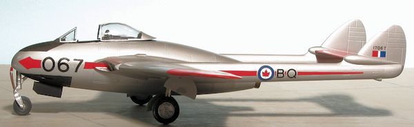 wer, to simplify manufacturing; and prominent "acorn" fairings at the junctions of the tailplane and tailfins.
The first Vampire F.3 -- not "F.III" this time around -- flew on 4 November 1946. It featured the Goblin 2 engine, more power being needed since maximum takeoff weight had increased by 50%. Range and endurance were as much as doubled. Deliveries of production aircraft began in the spring of 1947, with a total of 224 built from 1947 into 1949. The bulk of them, 118, went to the RAF. The Royal Navy also obtained six; Canada obtained 86, Norway 10, India 3, and Sweden 1.
Two Vampires were shipped to Singapore in early 1948 for test and trials under tropical conditions, with one used for static tests and the other for flight tests. The flight test aircraft then performed a tour of Far Eastern countries afterward, and flew to Khartoum in the Sudan for further trials in mid-March. It was back in the UK by the end of the year.
On hearing that the Americans were planning a jet crossing of the Atlantic, the British decided to trump them. In July 1948, six RAF Vampire F.3s under Squadron Leader R.W. Oxspring became the first jet aircraft to cross the Atlantic, performing hops through Iceland, Greenland, Labrador, and Newfoundland to end up in the US. The exercise demonstrated that jet aircraft were suitable for long-range operations. The Vampires then toured the US and Canada. One US Air Force (USAF) F-80 pilot took a flight in a Vampire and was suitably impressed. By that time, the F.3 was in squadron service in Europe and elsewhere.
| THE KIT |
 Nice to see a mainstream injected kit of this aircraft in this scale that has modern tooling and gets the shapes right. At least on a first look, it appears that there are no major glitches. Prior to this we had the Hobbycraft kit which had some major shape issues and the short run Classic Airframes version, which required quite a few modeling skills to get together without screaming and yelling!
Typical of modern Trumpeter kits, this one is superbly molded. It has a nicely detailed cockpit that only needs a harness to look proper. A decal is provided for the instrument panel though you could easily gussy up the plastic one with paint and drybrushing. interior side panels are also included. Like most Vampire kits, the interior and the nose gear well are intricately intertwined with the latter having very nicely done gear bracing for the strut. The strut appears to be properly extended as the Vampire usually sat tail low.
The upper and lower fuselage incorporate the wings, making assembly quite easy. One simply installed the main gear wells, the nose gear well, cockpit and tailpipe before closing the halves. Quite a bit of weight will be needed to prevent tail sitting so it is a good idea to tape the main components together, including the tail section to determine how much will be needed. Tail booms are like on just about every other Vampire kit and are two vertical halves that get attached to stubs at the end of the wing. The instructions would have to assemble the booms and horizontal stabilizer before attaching them to the wing/fuselage assembly.
 The landing gear is nicely formed and the inside of the gear wells and doors has acceptable detail. The engine intakes are separate pieces that fit in once the fuselage is completely together. These include the little vanes in the inside of the intakes. No intake trunking with this one. There is a two piece clear assembly consisting of the windscreen and separate canopy. You have your choice of drop tanks with those on pylons and conformal tanks for under the wing. Unfortunately, Trumpeter has decided that you WILL use the tanks and has already drilled holes in the lower wing for them. I wish they would let the builder decide.
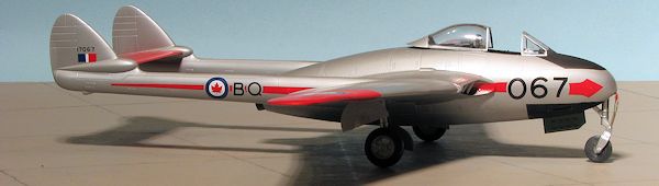
The bad part is that this is not an FB.9. Yep, the FB.9 had an air conditioning package that fit just in front of the right intake and this piece is completely missing from the kit. It will build into an FB.5 or FB.4, but you'll have to rely on aftermarket to build it as an FB.9. That being said, the serials included in the kits are both for FB.9s and so that means you will have to do some research to see if either of the two units (which are not identified) ever flew the earlier ones and make the proper serial number adjustments to match. I am sure there are or will be aftermarket Vampire sheets out to help in this regard. The box art plane is in the camouflage scheme and these will be gloss. The other options is for one in high speed silver with red fin/rudder/bullets.
Since writing the above information from the preview, I have been told that this kit is fatally flawed in so many ways that it almost makes the Hobbycraft kit look good. Apparently the only good part of the kit are the main wheels. The nose is the wrong shape, wings are too thin, horizontal stabilizer is the wrong chord, tail is the wrong shape, gear wells the wrong shape, fuselage is too wide, wings in the wrong place, plastic smells funny, etc.
| CONSTRUCTION |
Well, I had a good time building the Hobbycraft kit and decided to see if I would have a good time putting this one together or whether it would cause me to commit suicide because of all the errors. It couldn't be any harder to build than the Classic Airframes Vampire and it would be interesting to see how the two compared when I was done. Besides, I already paid for it so might as well build it, eh?
 One thing I have discovered about Trumpeter kits like this, they are usually well engineered and go together well. This is true of this kit as well. I started on the various subassemblies. Trumpeter likes to attach sprues to the gluing surface. This is great as it doesn't cause the builder to damage detail when removing the part or sanding down the stubs. However, it can cause oversanding and when these stubs are next to alignment pins, the pins often suffer.
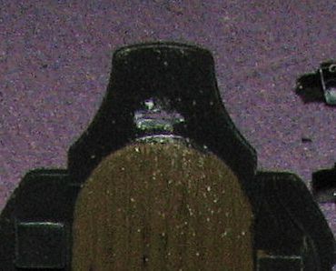
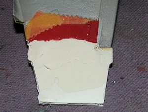
For this one I glued together the tail booms, the exhaust, the main wheels and most of the interior. I decided not to use the drop tanks so had to fill the holes Trumpeter already drilled there. These were later sanded down, but I put a bit of super glue over each one later and sanded again to help prevent these from creating small sink areas as the filler continued to cure. I also built up the nose gear well piece. The instructions are a bit vague on the placement of the gear well 'roof'. At least I thought so. The back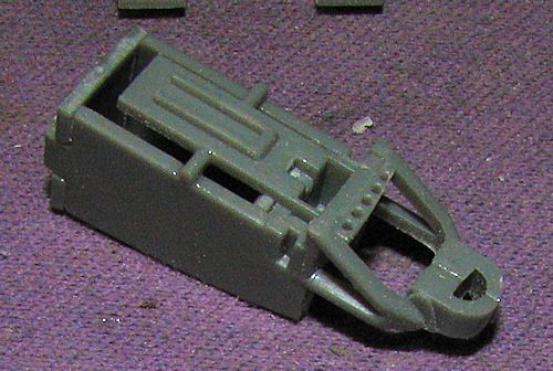 section of this should not mate up with the rear bulkhead as the drawing implies. I've a photo here of how it should look.
I then glued in the nose gear well piece, but not before putting some weight under the cockpit section that will fit atop this. I made sure it fit well before attaching it. I used 14 grams which should be enough to keep it on its nose gear. I thought it would be a good time for preliminary painting so the wheel wells, gear door insides and the nose gear well were painted British Interior Green using Humbrol paint. I did the interior section and sidewalls with matte black as well as the small piece that fits atop the nose gear assembly and the 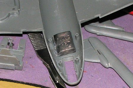 instrument panel with Matte Black, also from Humbrol. The landing gear parts and outside of the gear doors were painted aluminum using Alclad II, but this was a bit of a waste as the airframe was painted in High Speed Silver and I'll have to repaint those later in the build.
Meanwhile I drybrushed the interior bits to break up the mass of matte black. I used Microsol on the instrument decal and it worked superbly. I then built up the tail assembly by gluing the horizontal stab to the two tail booms. I have to confess that I was a bit nervous about doing this for fear of alignment woes, but my fears seemed unsubstantiated.
 After much inquiry and not finding much on the subject, I finally went with the later RAF harness in the cockpit. Probably dead wrong on this, but it is installed and looks nice. You will need to cut a slot in the armor plating so that the upper belt section can fit through it. I did so with an attachment on my motor tool and when done smoothed it out with some cement prior to installing the harness. I then glued the cockpit floor to the lower fuselage and then installed the sides and the
 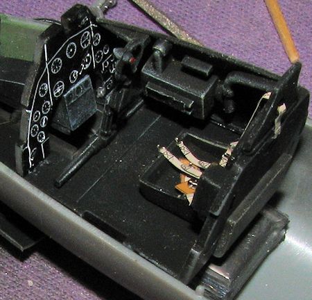 instrument panel. Probably should have installed these last items before putting the assembly into the fuselage, but it fit either way. To make sure I had enough weight, I taped the upper fuselage and tail booms in place and discovered that things were border line so added some more weight.
With the cockpit installed and the additional weight added, the fuselage halves were joined together. Fit is quite good except for one pin near the right tail boom. That was removed and the halves went together without fuss. I decided to go ahead and take care of the seams on the fuselage before installing the booms and the intakes to make it easier to sand. Predictably, I had small gaps where the sprue attachments joined the fuselage sections. This also seemed like a good time to take care of the wing tips. I sanded them flat and attached sections of .040 plastic card to them and reinforced the join with super glue. I then began the somewhat laborious job of sanding them to shape. Not sure that they are round enough, but I'm not going to do them again.
With that done, the lost detail was replaced and the tail booms and intakes attached. I expected to need filler for these pieces and so used it for the booms and the underside of the intakes, which were a very tight fit. I then masked the clear bits after sanding the filler and attached them. The small elevator balances were glued in place and I was ready to give it some paint.
| COLORS & MARKINGS |
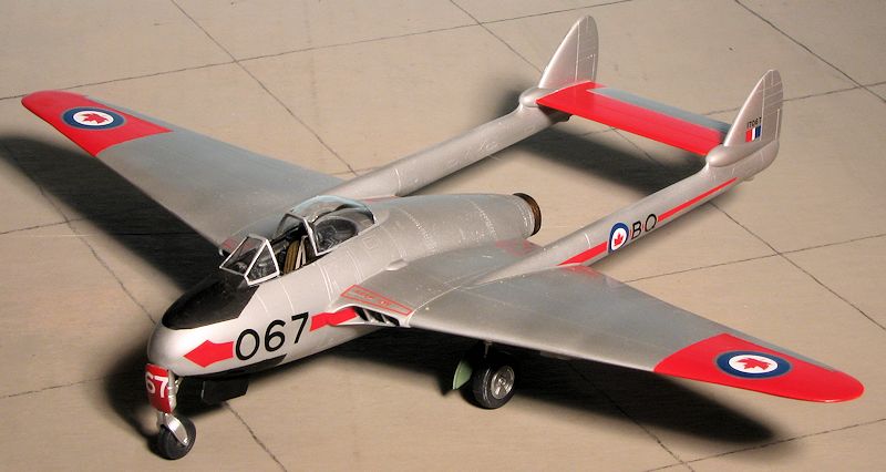
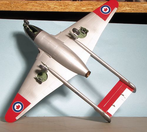
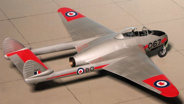
First thing I did was give it a coat of Tamiya primer, this showed some missed gaps and also that the filled holes in the lower wing had sunken in. A bit of super glue was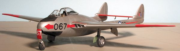 applied and sanded down before the primer was reapplied. I then painted the wing ends and the horizontal stabilizer white using Tamiya X-2. Over that was painted Tamiya XF-7 red, because I had no gloss red to use. I then realized I forgot the nose gear door so that got the same paint treatment. The red areas then got a gloss clear over them and when dry, they were masked off. I then painted the oversprayed area with more Tamiya primer and when dry, sprayed on Xtracolor RAL 9001 weissaluminum, which was to my mind, a good substitute for high speed silver. I also masked off and painted the black areas on the nose. Then it was off to the work bench to add more bits.
| FINAL CONSTRUCTION |
After pulling the masking away from the red areas, I realized that I simply could not live with the wing tips being the wrong shape so these were sawed away and new tips added. I had missed my self-imposed 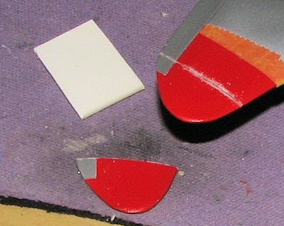 completion date so had another week
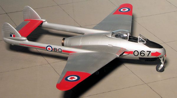
 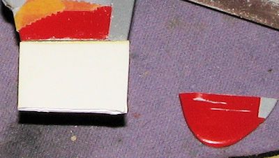 to work on things. So the first thing I did was to scribe where I wanted to cut the tips. The kit ailerons curved up to the tips at the end, but with the earlier tips, these were straight. Therefore, I cut the tips just before the curved section. As you can see from the images, the tips I originally moded were too peaked at the tips and curved up to follow the old aileron line. A rectangle of .040 plastic was glued on and reinforced with super glue. Since these were attached farther 'up' the wing, the .040 was actually a bit thinner than the tip. This required several applications of Tamiya putty to build up to the proper thickness.
 However, before doing that, I had to get the tips to the proper shape, which is a half circle curve. The first thing I did was to snip away those bits that were not in line with the wing. It was then that I added the first round of filler. Once that had dried, I then used a sanding stick to form the proper wing tips. This was a bit tedious, but it was important to get the proper curvature. I did not work from plans but simply an overhead drawing in the decal instruction sheet. When the proper curvature was reached, I then started smoothing out the filler and more of the plastic card in order to get the
 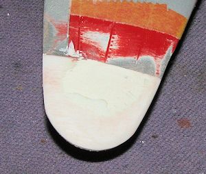 properly thin trailing edge and wing tip. Several more applications of filler were needed to get things properly smoothed out. It was a relatively long and careful process, but in the end, I feel it was worth the effort. Of course, my luck is that the next Trumpeter boxing will be an F.3. Once all that was done, more primer was applied to check for areas I missed and to allow me to rescribe the ailerons, panel lines and rivet detail. I then repainted the tips white, then red, then masked them and painted the ailerons with the RAL 9001.
To show that no good deed goes unpunished, when I removed the masking, I found a rather substantial ridge where I had left on the tape. This meant I needed to sand it down, remask, and repaint again. This would be the final time, regardless of the outcome. I pulled the masking off again and went to install the landing gear. But first, I painted the gear wells in British Interior Green. Right or wrong, that is how they will stay. I glued in the main gear legs and found them to be a very loose fit. Nose gear was nice and tight.
I now had it to where I could add the decals. For this one, I chose the new Leading Edge sheet #48.86. It was because of this sheet that I bought the kit and did the wing mods.
 Unlike the other options on the sheet, the Vampires have minimal stencils. I used just a few from the kit decals. The Leading Edge decals went on superbly and the silver backing for the red parts of the wing is as opaque as you could want. I did find that the nose gear door marking was a bit wide, but not surprising as the sheet was not designed for the Trumpeter kit. I used Microsol setting solution, but really only actually needed it on the intakes.
I then attached the rest of the bits. The main wheels and gear doors. A couple of notes. One is that even with all the weight I put in, it needs more and even after sticking a bit more in the nose gear well it will tail sit with a good bump. Second is that the outer gear doors are shown on the wrong side. The longer section goes to the rear. Third is that either the main gear legs are too long, the nose strut too short or a bit of both. The belly of a fully loaded (as in fuel) should be very close to the ground.
| CONCLUSIONS |
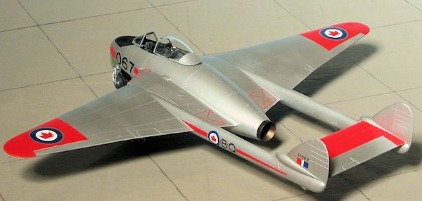
So there you have it. You don't have to go through all the machinations to alter the kit if you are building an FB5/6, but you can't build an FB.9 and to do an earlier version you do have to modify the wing tips. I've seen a model done using Canadian decals with the squared off tips and it just looks wrong.
 As for comparing it with other 1/48 Vampires, my only other references are the Hobbycraft kit and the Classic Airframes version. This one is visibly superior to the Hobbycraft kit, and with a direct side by side comparison with the Classic Airframes kit, I noted there were differences. The Trumpeter kit has a broader horizontal stabilizer that reaches farther into the 'bullets' on the fins. This is the most noticeable difference. The Trumpeter kit has an overall larger fuselage in diameter, the intakes are shallower on the underside, the shape of the gear doors is a bit different though similar, and the Classic Airframes kit has a greater angle at the transition from the outer wing panels to the inner section. I will leave this all to your judgment as to whether this is an issue. About the only thing that can be easily altered on the kit is the breadth of the horizontal stab.
| REFERENCES |
http://en.wikipedia.org/wiki/De_Havilland_Vampire
April 2013
Thanks to me for grabbing this one from the shelves of the LHS.
Copyright ModelingMadness.com. All rights reserved. No reproduction in any form without express permission from the editor.
If you would like your product reviewed fairly and fairly quickly, please
contact the editor or see other details in the