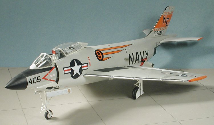
Grand Phoenix 1/48 F3H-2N Demon
| KIT #: | 006 |
| PRICE: | $69.95 MSRP |
| DECALS: | Two options |
| REVIEWER: | Scott Van Aken |
| NOTES: | Multimedia kit with resin and photo etched parts. |
| HISTORY |
The McDonnell F3H Demon was a US Navy carrier-based jet fighter aircraft. The successor to the F2H Banshee, after initial problems, it served from 1956 until 1964. Development work began in 1949, the aircraft was designed around only a single Westinghouse Electric Corporation J-40 engine, which was to have over 11,000 lb of thrust - three times that of the engines in the Banshee. It was the first swept-wing design produced by McDonnell and among the first US aircraft to have missile armament.
 The prototype first flew in 1951
and first test flights of the operational design were in January 1953.
The engine was a major disappointment, producing only half of the
expected power it was temperamental and unreliable, of 35 F3H-1 aircraft
that were flown with the J-40 engine eight were involved in major
accidents. The J-40 engined aircraft were grounded and a new engine was
sought. (In fact, brand new J-40 powered Demons were barged or trucked
directly to training schools and never flown, starting an investigation
into fraud by members of Congress. Things never change.) The best
alternative was destined for the F-100 Super Sabre and subsequent F3Hs
were fitted with the Allison J-71 engine (also used in the B-66) and
designated the F3H-2. While more reliable this new engine had to be
'shoe-horned' into the airframe and with less power than needed did
little for the aircraft's performance.
The prototype first flew in 1951
and first test flights of the operational design were in January 1953.
The engine was a major disappointment, producing only half of the
expected power it was temperamental and unreliable, of 35 F3H-1 aircraft
that were flown with the J-40 engine eight were involved in major
accidents. The J-40 engined aircraft were grounded and a new engine was
sought. (In fact, brand new J-40 powered Demons were barged or trucked
directly to training schools and never flown, starting an investigation
into fraud by members of Congress. Things never change.) The best
alternative was destined for the F-100 Super Sabre and subsequent F3Hs
were fitted with the Allison J-71 engine (also used in the B-66) and
designated the F3H-2. While more reliable this new engine had to be
'shoe-horned' into the airframe and with less power than needed did
little for the aircraft's performance.
The first Demon with a J-71 flew in October 1954. Another problem was with the ejector seats, initial versions could fail to operate and had to be replaced with Martin Baker models. Despite the problems in 1956 the Navy ordered 239 F3H-2s and the first were deployed in March 1956. 522 Demons of all versions were built up to the end of production in November 1959. It was the Navy's first all-weather interceptor with radar and the Raytheon Sparrow or Sidewinder AAM and remained the Navy's front-line fighter until 1962 when it was succeeded by the F-4 Phantom II. Although developed during the Korean War it did not see action, although it flew over Lebanon and Quemoy in 1958. With the more powerful engine, the aircraft was a delight to fly, though still rather short-legged.
| THE KIT |
For a look at the kit and what comes in the box, please visit the preview.
| CONSTRUCTION |
 As per SOP, I first looked for
subassemblies. Since this is a limited run kit, more prep than normal is
needed before starting into actual gluing. The kit provides what would be
about $40 worth of resin and the first thing that I did was to get the
really big parts with the large pour stubs and remove those pour stubs.
Naturally, a reviewer was harmed during this process when the saw slipped.
I really need to find a chain mail glove to use while doing this as I seem
to cut myself just about every time.
As per SOP, I first looked for
subassemblies. Since this is a limited run kit, more prep than normal is
needed before starting into actual gluing. The kit provides what would be
about $40 worth of resin and the first thing that I did was to get the
really big parts with the large pour stubs and remove those pour stubs.
Naturally, a reviewer was harmed during this process when the saw slipped.
I really need to find a chain mail glove to use while doing this as I seem
to cut myself just about every time.
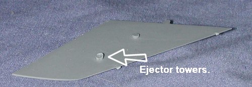
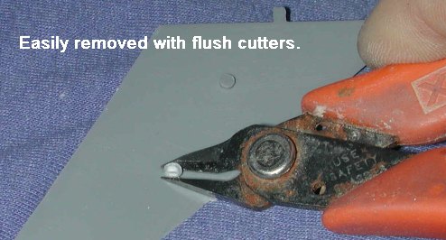
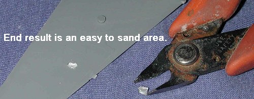
I also started removing the ejector stubs from the wings, tail planes and fin/rudder assembly. These are just one of the things that is normal with kits built in this way and they are actually very easy to remove as shown in the sequence below.
   |
Once they were cut off and sanded down, I glued together the fin/rudder and the tail planes. The wings need to have the resin wheel well inserts glued in place first. If you think you can glue them in without removing the pour stub, forget it as it will be too thick. Once sanded down, they were glued in place in the lower wing. Be sure that they are perfectly aligned as the upper wing is cut specifically to match the edges. I messed up on one side and had to trim the wing root a bit to get it to properly fit. I also glued in the speed brake wells. One side had to have the back sanded down a skosh as it was just a tad too long. As all that cured, I glued together the belly tanks.
All of the various subassemblies
needed a bit of filler here and there. Not unusual for me as I often expend
filler on every kit I build. Once those were properly sanded down, it was
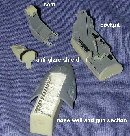
time to get with the program on the various bits and pieces. The kit
instructions have you start with the bang seat. This is the McDonnell seat
and not the later Martin Baker that was retrofitted
 to
the fleet. You get the base seat with separate head rest, pull handles and
an O2/mike line. This later piece was broken in my kit as it is quite
fragile. I also glued the etched sun shade on the anti-glare
panel/instrument panel part. This piece isn't notched so one just has to
form it over the existing resin part. In the cockpit, the control stick and
rudder pedals were glued in. The various teeny handles are already molded
on the tub and replacements are provided should they be needed. No really
good painting instructions are provided other than showing were the black
areas are. I was unable to find any color cockpit references. I also
discovered that the seat is a very tight fit so I had to sand down on the
attachment points for the seat pull handles to get them to fit. I also
glued the nose well into the gun section. The kit provides two different
gun sections, one with four and one with two guns. No indication is given
as to which is appropriate for these decals so I used the four gun version.
I also glued the flame grille onto the compressor section of the engine
which I'd already painted. This was glued into the exhaust tube. The
afterburner nozzle is
to
the fleet. You get the base seat with separate head rest, pull handles and
an O2/mike line. This later piece was broken in my kit as it is quite
fragile. I also glued the etched sun shade on the anti-glare
panel/instrument panel part. This piece isn't notched so one just has to
form it over the existing resin part. In the cockpit, the control stick and
rudder pedals were glued in. The various teeny handles are already molded
on the tub and replacements are provided should they be needed. No really
good painting instructions are provided other than showing were the black
areas are. I was unable to find any color cockpit references. I also
discovered that the seat is a very tight fit so I had to sand down on the
attachment points for the seat pull handles to get them to fit. I also
glued the nose well into the gun section. The kit provides two different
gun sections, one with four and one with two guns. No indication is given
as to which is appropriate for these decals so I used the four gun version.
I also glued the flame grille onto the compressor section of the engine
which I'd already painted. This was glued into the exhaust tube. The
afterburner nozzle is
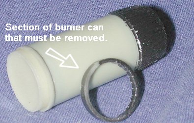 supposed to fit inside one end of the exhaust tube,
but it will not as its outer diameter is the same as the outer diameter of
the exhaust. It should be the the size of the inner section. It seems that
I'll have to cut off the indented part of the nozzle and butt glue it to
the exhaust pipe. Test fitting the exhaust area proved that it was what was
needed so a quick slice with the razor saw and the exhaust was ready to go.
supposed to fit inside one end of the exhaust tube,
but it will not as its outer diameter is the same as the outer diameter of
the exhaust. It should be the the size of the inner section. It seems that
I'll have to cut off the indented part of the nozzle and butt glue it to
the exhaust pipe. Test fitting the exhaust area proved that it was what was
needed so a quick slice with the razor saw and the exhaust was ready to go.
Now for more work on the cockpit.
This involved several actions. First of all, I test fit the seat. This
showed that it was too long to fit into the indentation provided.
Eventually, I had to trim the forward section of the seat and
 the
foot rests. I also used a chisel to remove a small section of the rear part
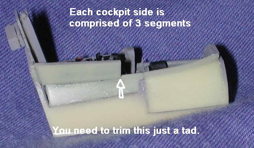
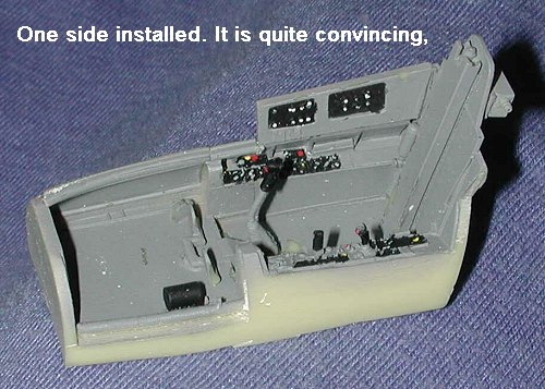
of the control column mount. Then it was time to fit the cockpit
sides. This is a pretty interesting construct. Each side has three parts; a
large forward section and two smaller aft pieces. The lower section of the
aft piece is a touch too short and doesn't fit all the way across. No
worries as long as the front part is in the right
the
foot rests. I also used a chisel to remove a small section of the rear part
of the control column mount. Then it was time to fit the cockpit
sides. This is a pretty interesting construct. Each side has three parts; a
large forward section and two smaller aft pieces. The lower section of the
aft piece is a touch too short and doesn't fit all the way across. No
worries as long as the front part is in the right
 place
as it butts up against the forward section. The upper aft piece is a
circuit breaker panel and it fits at an angle to the lower section. To get
this part to fit snugly, a tiny forward section of the lower piece must be
trimmed away. I tacked on the back section and then fit the cockpit into a
fuselage half. This gave me the proper alignment for the upper part. It was
then glued in place. The same procedure was done with the other side.
place
as it butts up against the forward section. The upper aft piece is a
circuit breaker panel and it fits at an angle to the lower section. To get
this part to fit snugly, a tiny forward section of the lower piece must be
trimmed away. I tacked on the back section and then fit the cockpit into a
fuselage half. This gave me the proper alignment for the upper part. It was
then glued in place. The same procedure was done with the other side.
 Into
the forward part of the cockpit fits the anti-glare panel/instrument panel
part. The instrument panel and instrument backing are held in place using
clear paint. Saves making a horrendous mess with super glue. Repeating the
mantra "test fit everything", I found that the forward section of the
anti-glare piece would not allow the cockpit to fit. I trimmed a very small
piece off the front of the cockpit section on the fuselage halves to ensure
a good fit. If it turns out that I needed to trim the resin part later,
I'll still have that option. I then glued a weight into the nose
(just in case) and glued together the forward fuselage halves, trapping the
resin cockpit. Then the nose wheel well assembly was glued in place. In
hindsight, I should have not glued the two gun portions to the wheel well
earlier and should have waited until I was ready to glue on the aft
fuselage halves onto the nose section.
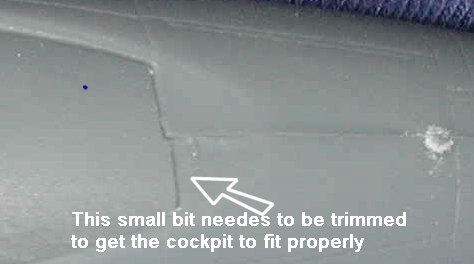
Into
the forward part of the cockpit fits the anti-glare panel/instrument panel
part. The instrument panel and instrument backing are held in place using
clear paint. Saves making a horrendous mess with super glue. Repeating the
mantra "test fit everything", I found that the forward section of the
anti-glare piece would not allow the cockpit to fit. I trimmed a very small
piece off the front of the cockpit section on the fuselage halves to ensure
a good fit. If it turns out that I needed to trim the resin part later,
I'll still have that option. I then glued a weight into the nose
(just in case) and glued together the forward fuselage halves, trapping the
resin cockpit. Then the nose wheel well assembly was glued in place. In
hindsight, I should have not glued the two gun portions to the wheel well
earlier and should have waited until I was ready to glue on the aft
fuselage halves onto the nose section.
 Speaking
of the aft section, I started gluing in the several vents and such that
would be straddling the two fuselage halves. As with all parts, I tacked
them in place then put the two halves together to ensure a good fit before
adding more adhesive to the one side of the part. This way, I knew that any
fit problems would be minimized when it came time to glue the two halves
together. There are two small vents about mid-fuselage, the tail hook
well and the upper exhaust shield that were glued in at this time. Fit on
all of them is good. Since I wanted to install the exhaust after the rear
fuselage had been painted, I took some scrap plastic card and made a crude
boxed in are. This way, all I have to do is apply glue to the end of the
compressor piece and shove it in. I've done this before and it really does
work!
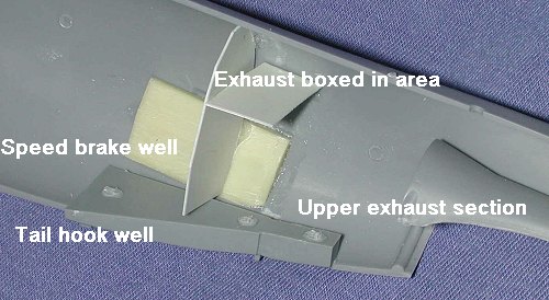
Speaking
of the aft section, I started gluing in the several vents and such that
would be straddling the two fuselage halves. As with all parts, I tacked
them in place then put the two halves together to ensure a good fit before
adding more adhesive to the one side of the part. This way, I knew that any
fit problems would be minimized when it came time to glue the two halves
together. There are two small vents about mid-fuselage, the tail hook
well and the upper exhaust shield that were glued in at this time. Fit on
all of them is good. Since I wanted to install the exhaust after the rear
fuselage had been painted, I took some scrap plastic card and made a crude
boxed in are. This way, all I have to do is apply glue to the end of the
compressor piece and shove it in. I've done this before and it really does
work!
With all that dry, it would be
possible for me to glue the two aft fuselage sections together and then
attach them to the front part. However, test fitting showed that there may
be an easier way, especially because the fuselage halves are so flexible.
There is a bulkhead that is glued to the back of the forward fuselage
section to help stiffen things and a wing spar is also provided. What I did
was glue one side of the fuselage to the nose section. When that was dry, I
cleaned up the joins and then glued the other fuselage half. The fit here
was ok, but I must have 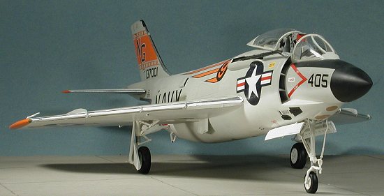 messed
up something because even though I test fit it a lot, I ended up with a
rather large gap just behind the canopy. Normally, this would be easy to
fix, however, I stupidly decided to glue the bottom seam first, wait for it
to cure and then do the top. Filler and super glue to the rescue on this
one!
messed
up something because even though I test fit it a lot, I ended up with a
rather large gap just behind the canopy. Normally, this would be easy to
fix, however, I stupidly decided to glue the bottom seam first, wait for it
to cure and then do the top. Filler and super glue to the rescue on this
one!
With the fuselage dry, and the first coat of filler sanded smooth, I added the tail piece. You'll need to sand and test fit this a number of times to get a good fit. When the fuselage halves were glued together, I found that the upper exhaust piece was just a tad on the short side and didn't reach all the way to the end of the opening in which it was to fit. Again, filler to the rescue. As you can see, if you need to be comfortable with your filling and sanding abilities in order to do any short run kits. The key is to take your time and not overdo it.
With the fuselage together and sanded smooth, I then turned to adding some additional stuff. In this case, I started with the fin/rudder. I had to enlarge the attachment holes a bit and then glued it in place. Making sure it was vertical to the rest of the fuselage was a bit tricky, but once on and dry, I applied filler to the usual gaps along the edge. The wings were a lot more tricky that I'd thought they would be. The additional wing spar was fine, but getting the two wings to be even was a real challenge. I ended up using some super glue in strategic areas to ensure they'd be even. This didn't work as well as I'd have thought and eventually I had to break loose the lower seam on one wing and install some card to bring the wing up and even. Again, none of this is really unexpected when doing these kinds of kits. It is all part of the experience. Personally, I like this kind of problem solving. It seems the more effort I put into a model, the more enjoyable an experience it is. Of course there is a limit, but this kit is no where near that!
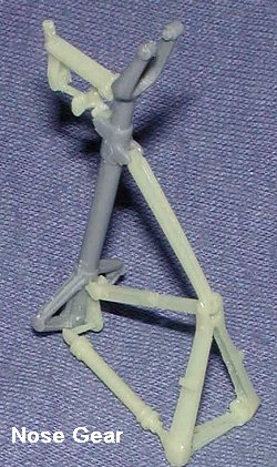 Then
I went to the landing gear. Without a doubt, this is one of the most
complex nose gears I've ever worked on. In addition to the plastic main
strut, there are eight other resin bits to glue in place. The instructions
are really not detailed enough to help in this area. Fortunately, the
reference has an excellent set of drawings for the landing gear so I was
able to pretty much figure out how stuff fit. I've included a photo of the
completed nose gear assembly for you to use as a reference when you get to
this stage on your kit. The only part that isn't totally accurate is the
central diagonal strut. It should meet down with the very bottom strut
attachment point (bottom as relative to the image), but I couldn't figure
out how to do this. There are also two lines that go from the bits near the
fork to the forward gear well that are put on after the gear is installed.
One is slightly curved to go around a landing light that isn't provided in
the kit.
Then
I went to the landing gear. Without a doubt, this is one of the most
complex nose gears I've ever worked on. In addition to the plastic main
strut, there are eight other resin bits to glue in place. The instructions
are really not detailed enough to help in this area. Fortunately, the
reference has an excellent set of drawings for the landing gear so I was
able to pretty much figure out how stuff fit. I've included a photo of the
completed nose gear assembly for you to use as a reference when you get to
this stage on your kit. The only part that isn't totally accurate is the
central diagonal strut. It should meet down with the very bottom strut
attachment point (bottom as relative to the image), but I couldn't figure
out how to do this. There are also two lines that go from the bits near the
fork to the forward gear well that are put on after the gear is installed.
One is slightly curved to go around a landing light that isn't provided in
the kit.
 While that was drying and before
tackling the main landing gear, I added a few more bits onto the airframe.
In this case it was the tail skid (glue it into the forward portion of the
well) and tail hook. I had to thin down the hook attachment points a bit to
get them to fit into the slots in the well. Then I glued on the upper wing
brakes and the long outer wing fences. These are both etched metal so take
care when cutting. The wing fences are rather fragile due to their thin
length. I tacked them down in a few spots with superglue and then used
clear paint run along the lower edge to fill the inevitable gaps and help
to keep it in place. I'll have to see how handling will affect these.
Frankly, I think that this is the perfect thing to use etched metal for.
These forms are basically two dimensional anyway. Using injected plastic
would just result in items that are too thick and they'd have to be sanded
down a lot to reach a more realistic thickness. However, for many that is a
preferable option so if you are having difficulty using etched metal you
might want to consider using the kit parts as a template for using plastic
sheet. The smaller leading edge fences were attached just using clear
paint. You could use Future, but I find it a bit too thin for applications
like this.
While that was drying and before
tackling the main landing gear, I added a few more bits onto the airframe.
In this case it was the tail skid (glue it into the forward portion of the
well) and tail hook. I had to thin down the hook attachment points a bit to
get them to fit into the slots in the well. Then I glued on the upper wing
brakes and the long outer wing fences. These are both etched metal so take
care when cutting. The wing fences are rather fragile due to their thin
length. I tacked them down in a few spots with superglue and then used
clear paint run along the lower edge to fill the inevitable gaps and help
to keep it in place. I'll have to see how handling will affect these.
Frankly, I think that this is the perfect thing to use etched metal for.
These forms are basically two dimensional anyway. Using injected plastic
would just result in items that are too thick and they'd have to be sanded
down a lot to reach a more realistic thickness. However, for many that is a
preferable option so if you are having difficulty using etched metal you
might want to consider using the kit parts as a template for using plastic
sheet. The smaller leading edge fences were attached just using clear
paint. You could use Future, but I find it a bit too thin for applications
like this.
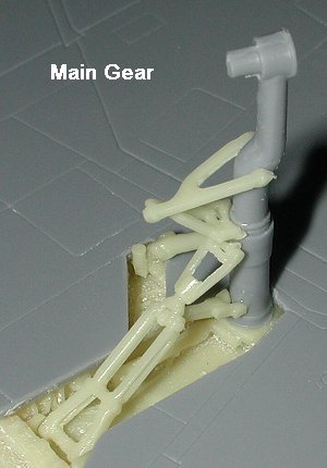 With those on, My attention turned to
doing the main landing gear. These are nearly as complex, but only have
five resin bits to attach to each gear leg! Thanks to my getting the one
gear well crooked, I had to cut a bit out of the wing in order for the gear
leg to fit. Again, the reference was used and it was quite helpful.
With those on, My attention turned to
doing the main landing gear. These are nearly as complex, but only have
five resin bits to attach to each gear leg! Thanks to my getting the one
gear well crooked, I had to cut a bit out of the wing in order for the gear
leg to fit. Again, the reference was used and it was quite helpful.
Now that it was on its gear, I could start adding all the various little bits and pieces. There are two injected fuel vents that attach to either side of the tail hook. For resin bits, two small antennas fit just on the trailing edge of the wing tips. These have small stand-offs so don't cut them flush with the hemispherical part. On the rear are four scoops that are provided in resin. There is also what appears to be an upper fuselage light blister that is in resin. The kit provides an extra or two for these in case one goes away. Looking in the box to see what else I might need to add I ran across the wing tip pitot tube. It is supposed to be curved on the tip so don't try to straighten it out. It should fit inboard of the wing tip and a bit more forward than is shown in the instructions. Finally, I noticed that I'd forgotten to install the intake separators. Well, these were way too wide, either because I should have glued them in earlier or because they are too wide. Regardless, I had to spend some time sanding them down to where I could get them to fit in place. With all that stuff finally glued in place, it was time for some paint.
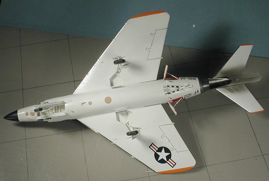
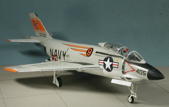
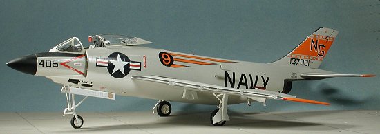
| COLORS & MARKINGS |
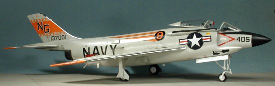 I masked off the cockpit area and
painted the entire underside of the fuselage (including landing gear and
wells), the gear doors, the stabilators, the upper surface control
surfaces, wing tips, and the speed brake bits with Floquil Reefer White.
Imagine my thrill when I notice that a big seam had opened up on the
underside during construction. I hadn't seen it until I sprayed on the
Floquil! Once the white had dried, I filled and sanded this seam and a few
others that I'd noticed. One thing about Reefer White is that it makes a
great primer! After fixing the glitch, I painted the upper surface with
Testors ModelMaster Light Gull Grey enamels. Then I did the usual back and
forth with colors. I should mention that I pushed the speed brakes into
place as much as I could. The resin parts are larger than the openings and
were I smart, I'd have trimmed the openings and fit these parts before
doing any work on the fuselage at all. It will save a lot of hassles later
I can guarantee you. I then masked off the exhaust area and painted that
with Alclad II Steel. The radome was also masked off and painted flat
black.
I masked off the cockpit area and
painted the entire underside of the fuselage (including landing gear and
wells), the gear doors, the stabilators, the upper surface control
surfaces, wing tips, and the speed brake bits with Floquil Reefer White.
Imagine my thrill when I notice that a big seam had opened up on the
underside during construction. I hadn't seen it until I sprayed on the
Floquil! Once the white had dried, I filled and sanded this seam and a few
others that I'd noticed. One thing about Reefer White is that it makes a
great primer! After fixing the glitch, I painted the upper surface with
Testors ModelMaster Light Gull Grey enamels. Then I did the usual back and
forth with colors. I should mention that I pushed the speed brakes into
place as much as I could. The resin parts are larger than the openings and
were I smart, I'd have trimmed the openings and fit these parts before
doing any work on the fuselage at all. It will save a lot of hassles later
I can guarantee you. I then masked off the exhaust area and painted that
with Alclad II Steel. The radome was also masked off and painted flat
black.
Then it was on to the decals. I
started by applying all the standard markings, which includes the wing walk
area. Here again, I ran into a bit of a problem. You see, I'd already glued
down the wing mounted air brakes, but these are not covered by the walk
areas. This meant trimming them and the trailing edges are a jagged design
that is near impossible to cut properly. I
 highly recommend not installing
these etched brakes until after you put down the wing walk decal.
Eventually the screw-ups were fixed by using a black drafter's pen. Now for
another glitch (and there are more to come). The leading edges of the wings
are supposed to be bare aluminum. Yup, this means that all those small
fences I installed would be very much in the way of things. I did manage to
get some Bare Metal Foil matte Aluminum in between these fences and only
knocked off one small one (which then managed to disappear to who knows
where). I recommend installing only the large fence before painting, and
then put all the little ones on after the kit is painted and decaled. They
are supposed to be bare metal anyway so no worries on painting. Now for the
final glitch. The rudder on this aircraft is not supposed to be painted
white as is the norm and I'd already painted it white. This meant I had to
paint it and that delayed things.
highly recommend not installing
these etched brakes until after you put down the wing walk decal.
Eventually the screw-ups were fixed by using a black drafter's pen. Now for
another glitch (and there are more to come). The leading edges of the wings
are supposed to be bare aluminum. Yup, this means that all those small
fences I installed would be very much in the way of things. I did manage to
get some Bare Metal Foil matte Aluminum in between these fences and only
knocked off one small one (which then managed to disappear to who knows
where). I recommend installing only the large fence before painting, and
then put all the little ones on after the kit is painted and decaled. They
are supposed to be bare metal anyway so no worries on painting. Now for the
final glitch. The rudder on this aircraft is not supposed to be painted
white as is the norm and I'd already painted it white. This meant I had to
paint it and that delayed things.
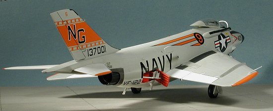
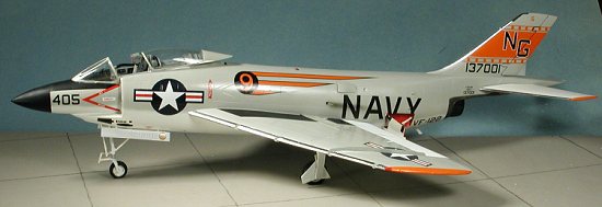
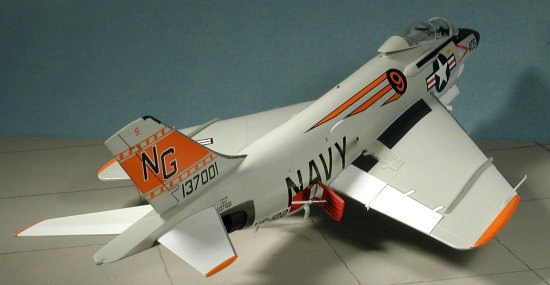
OK, now for the rest of the decals. I used the VF-122 markings with the orange wing and stab tips. The decals won't totally cover the tips, but Humbrol 18 orange is as much an exact match so you can either paint the tips with the Humbrol (recommended) or do as I did and use it for touch-up. The large NAVY markings on the rear have to go over the vents and stuff there so it will take several applications of Sovaset to get things to finally snuggle down. I also stupidly removed the speed brakes and did all the touch-up painting on the brakes and fuselage when I realized I needed to leave them in place for the unit decal. I cheated and put it in a non-standard place. On the nose you need to match the anti-glare panel with the radome to get it to be in the proper place. However, this will leave an area forward of the windscreen to be painted. I put mine on too far back to cover the area in front of the windscreen with the result that I had to use some touch-up paint to cover the gap. I left off the tail hook stripe decals until the hook was glued in. You'll need to trim off one of the four black squares before applying as this decal is too long. BTW, the decals are by Eagle Strike (natch) and printed by Cartograf in Italy. They are superb with excellent color and they reacted well to the Solvaset I used.
| FINAL CONSTRUCTION |
OK, now for some of the final bits. First, I went for the wheels. The main wheels need to be drilled out considerably to stick on the axle stubs. There is no indication as to which way they go, but the reference shows that the deep portion is facing the strut. There are no brakes to put in the wheels, which I guess was missed. The nose wheel was slipped in place and then they were aligned with the flat spots on the bottom and glued with super glue. Stabilators were just pushed into place.
 Next came the gear doors.
Instructions are a bit vague here as well, but thanks to the reference, I
was able to put them on in something like what they should be like. The
lower piece has to have the strut centered in the openings (you'll see what
I mean when you get to it). The very small door goes lengthwise on the
inboard section of the opening. The others are pretty easy to figure out. I
had to do some touch-up painting on these as the sprue attachments are a
bit thick and some run into the part itself, necessitating additional
sanding prior to repaint. You don't have to do the thin red strip around
the edge of the doors on this aircraft unless you want to. I've seen photos
both ways. I've also seen photos of the entire inner door painted red so
you can do that as well if you wish.
Next came the gear doors.
Instructions are a bit vague here as well, but thanks to the reference, I
was able to put them on in something like what they should be like. The
lower piece has to have the strut centered in the openings (you'll see what
I mean when you get to it). The very small door goes lengthwise on the
inboard section of the opening. The others are pretty easy to figure out. I
had to do some touch-up painting on these as the sprue attachments are a
bit thick and some run into the part itself, necessitating additional
sanding prior to repaint. You don't have to do the thin red strip around
the edge of the doors on this aircraft unless you want to. I've seen photos
both ways. I've also seen photos of the entire inner door painted red so
you can do that as well if you wish.
I then moved back to the speed brakes. These fit well though they seem a bit too open to me. Most photos show them either closed or just barely cracked open. The well and inside of the speed brake itself should be red with a white actuating strut. I then sprayed the areas that are supposed to be matte black, like the anti-glare and wing walk decals with matte clear.
Then I took the mask off the
transparencies. The canopy turned out just fine, but the windscreen didn't.
Not only did paint seep under the mask, but glue did as well and it isn't
pretty. I'll stick to Tamiya tape in the future as it seems the Eduard
masks are not sticky enough. I ran into this problem with their wheel masks
as my airbrush blew several of them off, necessitating a repaint of the
wheels in question. Then the seat was installed after the seat belts were
glued in. It seems that even after all my work, the seat is a tad too high.
I glued the canopy in the open position to show off the interior and then
sprayed the exhaust area with Tamiya Smoke acrylic. I also sprayed the oil
scavenge opening with a bit of this.
 These engines didn't have an
oil return so, like the A-4, oil routinely was sprayed overboard through
openings in the side. Normally, these would have been wiped down as part of
prepping the plane for the next mission, but after time, a definite streak
was present.
These engines didn't have an
oil return so, like the A-4, oil routinely was sprayed overboard through
openings in the side. Normally, these would have been wiped down as part of
prepping the plane for the next mission, but after time, a definite streak
was present.
The last parts were painting the formation lights and gluing in the refueling probe. This last item is either a bit too short or I glued the housing too far back (probably the latter). I then called it quits even though I should have painted the forward wing tip antennas that surround the formation lights black as they are this color in every photo I've seen. I also blew off reattaching the lower wing tip antennas that I broke off during handling. As for the drop tanks, I forgot all about them so while they have been built, they've not been painted. I'll attach them at a later date....perhaps.
| CONCLUSIONS |
I have to say that it was quite an adventure building this kit. It wasn't the near piece-of-cake that I thought it would be when starting, but I think that is because there are so many detail parts. Overall, I enjoyed building this one quite a bit. There were a few challenges to overcome and I expected there would be. I can see that this isn't the easiest kit to engineer and appreciate some of the methods used for getting this together. The end result is a really superb model of a most interesting aircraft. I'm frankly quite surprised at how large it is as it easily compares in size to the F-4 Phantom in overall length. If you have an interest in 1950s US Naval aircraft and can handle the challenges of a short run multimedia kit like this, then go for it. You won't be disappointed.
September 2004
#1334 in a series
| REFERENCES |
McDonnell F3H Demon by Steve Ginter, 1985. Naval Fighters # 12.
Thanks to Grand Phoenix for the review kit. As a note, Grand Phoenix is now out of business so any kits will have to come from the 'second hand' market.
If you would like your product reviewed fairly and fairly quickly, please contact the editor or see other details in the Note to Contributors.