| KIT #: | 72221 |
| PRICE: | $32.99 SRP |
| DECALS: | One option |
| REVIEWER: | Scott Van Aken |
| NOTES: | Short run kit |
| HISTORY |
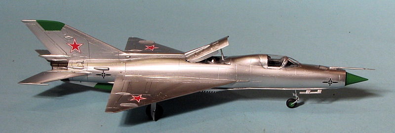
Have to resort to the kit instructions for this. One thing I did find out is that this aircraft is probably more correctly called the Ye-7PD or the MiG-21PD
 "In September 1962, the design bureau OK-155 started to design a new MiG-23PD
aircraft. The development of the fighter started after the CPSU Central
Committee issued a decree, under which such variants had to be considered:
the aircraft powered by the RD-36-35 lift engines and by the R21F-300 and
R27F-300 power jet engines. The MiG-21 PFS was modified into the experimental
Ye-7PD to test the engines. The fuselage became 900 mm longer to house the two
jet lift engines mounted after the cockpit. The Ye-7PD made its maiden flight on
16 June 1966. The Ye-7PD (23-31) aircraft demonstration at the Domodedovo Air
Parade in 1967 was its moment of glory. Tested takeoff and landing device found
use in the Yak-38 aircraft. After the researches were finished, the 'MiG' was
given to the Airplane Design Department of the Moscow Aviation Institute as an
educational aid."
"In September 1962, the design bureau OK-155 started to design a new MiG-23PD
aircraft. The development of the fighter started after the CPSU Central
Committee issued a decree, under which such variants had to be considered:
the aircraft powered by the RD-36-35 lift engines and by the R21F-300 and
R27F-300 power jet engines. The MiG-21 PFS was modified into the experimental
Ye-7PD to test the engines. The fuselage became 900 mm longer to house the two
jet lift engines mounted after the cockpit. The Ye-7PD made its maiden flight on
16 June 1966. The Ye-7PD (23-31) aircraft demonstration at the Domodedovo Air
Parade in 1967 was its moment of glory. Tested takeoff and landing device found
use in the Yak-38 aircraft. After the researches were finished, the 'MiG' was
given to the Airplane Design Department of the Moscow Aviation Institute as an
educational aid."
If you have the Yefim Gordon tome on the MiG-21, there are several pages and color photos of this aircraft included within.
| THE KIT |
From the initial look of things, Amodel took a MiG-21 kit and supplied new sprues for the fuselage and for the bits around the lift engines. However, I am pretty sure that all the sprues are dedicated to this kit as there are some bits on most sprues that are not typical MiG-21, like the long cable ducting fairings along side the fuselage. The molding is really quite good, though there is a bit of flash that will need to be taken care of.
 The surface detailing is admirably crisp and the sprue gates are small. Some
of the thicker parts, like the forward fuselage where there are alignment stubs
for the fuselage, have sink areas that will need to be filled. The sprue gates
are admirably small, but on some parts, such as the long and thin cable ducting,
the gates invade the part and will need to be sanded away once the part is
removed.
The surface detailing is admirably crisp and the sprue gates are small. Some
of the thicker parts, like the forward fuselage where there are alignment stubs
for the fuselage, have sink areas that will need to be filled. The sprue gates
are admirably small, but on some parts, such as the long and thin cable ducting,
the gates invade the part and will need to be sanded away once the part is
removed.
A basic cockpit is provided that consists of a tub, seat and control stick. The instrument panel and area behind the seat are separate and join onto the fuselage proper. Lift engine faces are well done and on can pose the upper door open. The lower doors are molded open. I found it interesting that the nose gear well is a box with a separate upper piece. All of the various scoops and fairings are separate pieces with no area on the fuselage delineated for exactly where they go. Landing gear is quite adequate for the kit. I do not think it needs nose weight as none is indicated, but I am gun-shy and will add some.
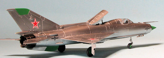
Instructions are well drawn and provide color information with Humbrol and generic color names. As is typical of Soviet aircraft of the time, this one is bare metal and red stars. Photo calibration marks are also included. You get eight stars but only need six of them. Amodel decals are quite matte and my experience with them is that they are OK, but best replaced with aftermarket if one can. Not likely with this aircraft, though there are insignia sheets that might prove useful.
| CONSTRUCTION |
 First thing I did was to paint the cockpit colors. The
instructions state a grey, but everyone knows that MiGs have that blue green
cockpit color so that is the color I used. Well, I began to have some doubts
after doing a bit of 'net research and sure enough, in the reference book, there
is a color photo that shows this plane in the Moscow Aviation Institute and the
cockpit is grey. Apparently the change-over came in the mid-1960s so while some
production MiG-21F aircraft will have the newer color, the early ones will not.
I used Neutral Grey for the repaint and it looks convincing enough, though it is
barely darker than the plastic. I also took this opportunity to fill the rather
prominent sink marks on the outside of the nose of the fuselage with super glue.
First thing I did was to paint the cockpit colors. The
instructions state a grey, but everyone knows that MiGs have that blue green
cockpit color so that is the color I used. Well, I began to have some doubts
after doing a bit of 'net research and sure enough, in the reference book, there
is a color photo that shows this plane in the Moscow Aviation Institute and the
cockpit is grey. Apparently the change-over came in the mid-1960s so while some
production MiG-21F aircraft will have the newer color, the early ones will not.
I used Neutral Grey for the repaint and it looks convincing enough, though it is
barely darker than the plastic. I also took this opportunity to fill the rather
prominent sink marks on the outside of the nose of the fuselage with super glue.
For the next step, I started assembling subassemblies. This included the upper and lower lift engine assemblies and that tailpipe. I also glued the upper section to the nose gear well and the strakes on the inside of the upper lift engines door. Both the upper and lower lift engine compressor pieces require the compressor faces to be installed from the inside, so be aware of that. Also note that these will be angled slightly to the rear.
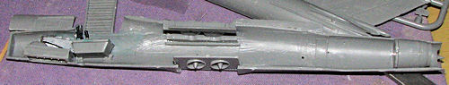 Once these were
glued and dry, I started installing them into a fuselage half. The halves are a
bit warped and it is imperative that once a section is glued in place, that the
halves be temporarily joined to ensure these dry with the proper alignment. I
first installed the nose wheel well, then the exhaust section. Moving on, I did
the upper compressor assembly. This one wanted to not fit into the alignment
ledge on the other half and had to be prodded into place from the underside so
do not install the lower section first. It was a bit of a trial, but finally it
was in place. The last two bits were the lower compressor assembly and then the
interior. I also added weight in the nose just to be sure.
Once these were
glued and dry, I started installing them into a fuselage half. The halves are a
bit warped and it is imperative that once a section is glued in place, that the
halves be temporarily joined to ensure these dry with the proper alignment. I
first installed the nose wheel well, then the exhaust section. Moving on, I did
the upper compressor assembly. This one wanted to not fit into the alignment
ledge on the other half and had to be prodded into place from the underside so
do not install the lower section first. It was a bit of a trial, but finally it
was in place. The last two bits were the lower compressor assembly and then the
interior. I also added weight in the nose just to be sure.
As you might imagine, there was plenty of filler needed for this one. I found that the lower exhaust area was short shot on one side so that needed to be taken care of. I also forgot to put the rear bulkhead in the upper cockpit section so added that little detail. There is still a considerable gap to the cockpit tub so you may want to use some card to fill that. I do not plan on having the canopy open so left it. During all this filling I installed the nose ring. Fortunately, one can leave off the radome until the kit is done. I also did some trimming to ensure that the lower vanes would fit. I did find that I had to cut off the exhaust cones of the lift engines to get this piece to fit. Not really an issue as there is little to be seen through the thick vanes.
 I then attached the wings. Fit at the root is not very good
and even after a lot of trimming, I ended up using considerable filler. With the
wings in place, I returned to the cockpit and installed the seat. Then the clear
bits. These are quite thick and have large attachment points. They also do not
fit well at all. Not only that, but I managed to crack the canopy. After
trimming it and the windscreen to get it to fit, I found that the windscreen is
not as wide as the canopy. I fudged mine together, but recommend aftermarket for
this one.
I then attached the wings. Fit at the root is not very good
and even after a lot of trimming, I ended up using considerable filler. With the
wings in place, I returned to the cockpit and installed the seat. Then the clear
bits. These are quite thick and have large attachment points. They also do not
fit well at all. Not only that, but I managed to crack the canopy. After
trimming it and the windscreen to get it to fit, I found that the windscreen is
not as wide as the canopy. I fudged mine together, but recommend aftermarket for
this one.
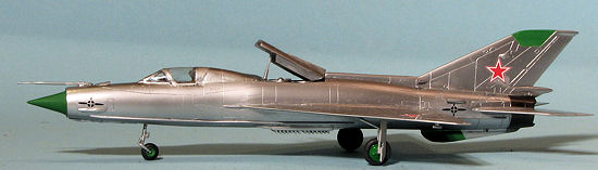
Next were the cable ducts that go along the fuselage. These are very thin and so great care is needed in removing them from the sprue and cleaning up the five sprue attachment points. To install these, I first attached the very front, then while the glue was still tacky, attached the rear and then the bits in between. This seemed to work quite well. A bit of filler is needed where the duct starts and joins to the bit molded on the fuselage. Next, the tailplanes were glued in place. Fit is fair but they do not line up 100% with the fuselage root area.
A real fit issue came with the canopy pieces. First, I installed the seat to make sure it wasn't too tall. Then , while trimming the excess plastic from the canopy, managed to put a crack in it that went almost all the way across. Fit on this is poor and I had to sand away quite a bit of it to get it to match the space into which it should fit. The windscreen was equally difficult to clean up thanks to the thick plastic. When placing it on the airframe, I was disappointed to notice that it is not as wide as the canopy, so there is a rather noticeable step between the windscreen and canopy section. These were duly masked, not an easy task thanks to the rather indistinct frames.
 Since the
model was to be overall metal, I decided to install the upper inlet door and all
the small scoops that fit on the rear section. These scoops have no indicator
area as to where they are supposed to fit so one just takes an estimate from the
four view drawing that is supplied. These scoops require quite a bit of
clean-up, especially the mounting surface. Not an easy task because of the small
size. Back at the upper inlet door, I ended up carving the back of the small
side plates to the proper angle so it would fit in place. In the front, there
are a number of items to install, including the upper pitot tube and some
triangular vents. These vents have pins on the bottom of them that fit into
holes in the fuselage. The upper hole had to be enlarged and the lower one
drilled. Then it was time to paint.
Since the
model was to be overall metal, I decided to install the upper inlet door and all
the small scoops that fit on the rear section. These scoops have no indicator
area as to where they are supposed to fit so one just takes an estimate from the
four view drawing that is supplied. These scoops require quite a bit of
clean-up, especially the mounting surface. Not an easy task because of the small
size. Back at the upper inlet door, I ended up carving the back of the small
side plates to the proper angle so it would fit in place. In the front, there
are a number of items to install, including the upper pitot tube and some
triangular vents. These vents have pins on the bottom of them that fit into
holes in the fuselage. The upper hole had to be enlarged and the lower one
drilled. Then it was time to paint.
| COLORS & MARKINGS |
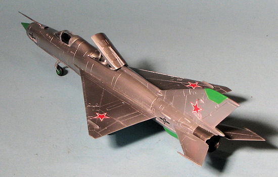
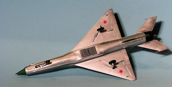
Color photos of the prototype in the reference show it to be a gleaming, almost polished airframe. No difference in panel shades could be seen. Now it would look pretty toy-like if it was painted a near polished color so I just used standard Alclad II Aluminum. This was sprayed onto the bare plastic, and it showed several areas that needed more work.
 Back to the
bench for a bit more filler and some more sanding. I also took the opportunity
to install the landing gear. The front gear leg required some trimming to fit
fully and the main gear was a bit on the tricky side as well. It is easy to
install the main gear legs on the wrong side. Just watch to make sure the
retraction strut indentation is on the front. I also glued on the rather unusual
looking antenna on the front.
Back to the
bench for a bit more filler and some more sanding. I also took the opportunity
to install the landing gear. The front gear leg required some trimming to fit
fully and the main gear was a bit on the tricky side as well. It is easy to
install the main gear legs on the wrong side. Just watch to make sure the
retraction strut indentation is on the front. I also glued on the rather unusual
looking antenna on the front.
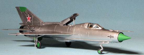
A return to the paint shop to finish the painting. When dry, the radome areas were masked off and painted green using Humbrol 101 as recommended in the instructions. If you do not have this shade, you can use Testors green paint in the small bottles, though it will be gloss. A bit more drying time and the exhaust area was masked off and painted Alclad II Steel. Actually, I should have done this before attaching the tail planes as it would have been easier.
| FINAL CONSTRUCTION |
I realized that I had forgotten to glue on the lower
exhaust piece for the lift jets so cleaned that part up and glued it in place.
Before gluing it, I had to cut off the compressor center pieces as they
prevented the lift jet vales from fitting. This piece is narrower than the area
it has to fill. It also needed quite a bit of filler so more time sanding and
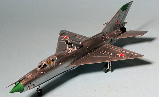
then painting once again. The lower wing tip doppler antennas were then glued
in. These fit very well into small recesses, a much better way of doing things
that simple butt joins. The main gear doors have some prett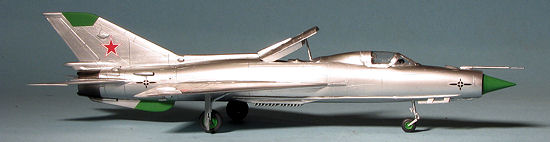 y
hefty sink areas so those were filled before the doors were painted and
installed. This aircraft did not have any nose gear doors according to the
photos so those were left off. For the wheels, I used the same green as used on
the radomes. The nose radome was the last piece to install, and it is a little
bit larger than the opening. I sanded the lower circumference until it fit.
y
hefty sink areas so those were filled before the doors were painted and
installed. This aircraft did not have any nose gear doors according to the
photos so those were left off. For the wheels, I used the same green as used on
the radomes. The nose radome was the last piece to install, and it is a little
bit larger than the opening. I sanded the lower circumference until it fit.
Unusually, the last thing to do was to apply the decals. These are OK decals. They stick well but seem to be impervious to setting solutions. At least, they are not thin enough to conform to the engraved panel lines. I then unmasked the canopy and cleaned up the small amount of seepage that occurred. I also brushed on some Future to hopefully help hide the crack. Not much help, actually. I just have a shiny cracked canopy!
| CONCLUSIONS |
This kit is not everyone's cup of tea. The kit itself requires more work than many might be willing to make, especially as every join needs to be test fit and often trimmed or fixed with filler. The poor fitting windscreen was a bit of a let down. However, if you are good at working with iffy-fitting kits, and want something unusual, then this is something you should consider.
| REFERENCES |
Kit instructions
Mikoyan MiG-21, by Yefim Gordon. Midland, 2008
November 2012 Thanks to me for picking this one up. Copyright ModelingMadness.com. All rights reserved. No
reproduction in part or in whole without express permission from the editor.
If you would like your product reviewed fairly and fairly quickly, please
contact
the editor or see other details in the
Note to
Contributors.