Anigrand 1/72 Atlas ICBM
| KIT #: | AA-2064 |
| PRICE: | $64.95 MSRP |
| DECALS: | One option |
| REVIEWER: | Scott Van Aken |
| NOTES: | Resin, makes one of three variants |
 A development contract for the Atlas was awarded to Convair in January 1955, and Convair completed construction of the test stands in 1956. Convair Division of General Dynamics Corporation conducted static test firings of an Atlas missile at its Sycamore Canyon test facility northeast of San Diego.
The Atlas A was the first R&D configuration that ultimately led to the operational Atlas D, E, and F missiles. It consisted of minimum propellant, propulsion, and guidance systems. Its maximum range was only 600 nautical miles, and its maximum altitude was 57.5 nautical miles. A total of eight Atlas As were launched--all on the Atlantic Missile Range--during the period June 1957 to June 1958. The B series was the second Atlas developmental configuration. Its propulsion system was close to operational capability, and one series B missile traveled 5,500 nautical miles down the Atlantic Missile Range. Atlas 4-B, the second in the series B test flights, was launched successfully on 2 August 1958. The eighth missile in the series, Atlas 10-B, placed itself into orbit with the Project SCORE payload on 18 December 1958, becoming the world’s first communications satellite in the first successful use of the Atlas as a space launch vehicle.
The Convair Division of General Dynamics produced three different models of the Atlas ICBM destined for deployment with the Strategic Air Command. The first operational version of the Atlas, the "D" model, was a one and one-half stage, liquid-fueled, rocket-powered (360,000 pounds of thrust) ICBM equipped with radio-inertial guidance and a nuclear warhead. It was stored in a horizontal position on a "soft" above-ground launcher, unprotected from the effects of nuclear blast, and had an effective range, like all Atlas models, of approximately 6,500 nautical miles. The second Atlas ICBM configuration, the series E, possessed all-inertial guidance, improved engines (389,000 pounds of thrust), a larger warhead, and was stored in a horizontal position in a "semi-hard" coffin-type launcher. The series "F" missile was superior to its predecessors in several ways. Like the E model, the Atlas F was equipped with all-inertial guidance, but possessed improved engines (390,000 pounds of thrust) and a quicker reaction time due to its storable liquid fuel. The Atlas F missiles also were deployed in "hard" silo-lift launchers which stored the missiles vertically in underground, blast-protected silos and used elevators to raise the missiles to ground level for launch.
Meanwhile, considerable progress was made in developing secon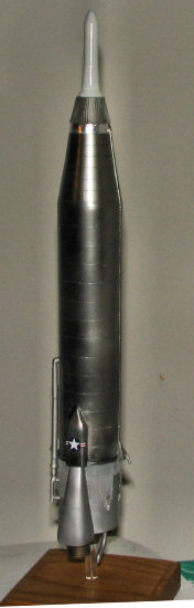 d-generation ICBMs such as the Minuteman. Among the numerous advantages the newer missiles had over the Atlas was their ability to be launched from hardened and widely dispersed underground silos. Minuteman was also more economical to operate, more reliable, and because of its silo-launch capability, better able to survive a nuclear first strike than their first-generation counterparts.
Consequently, on 24 May 1963, General Curtis E. LeMay, Air Force Chief of Staff, approved the recommendations of the Air Force Ad Hoc Group for phaseout of Atlas D by the end of FY 1965 and the Atlas E's by the end of FY 1967. On 16 May 1964, Secretary of Defense Robert S. McNamara accelerated the phase-out of the Series E Atlas from the end of FY 1968 to the close of FY 1965. In addition, Secretary McNamara ordered the retirement of all Atlas F ICBMs by the end of FY 1968.
Project "Added Effort", the Air Force nickname for the programmed phaseout of all first-generation IC8Ms, began on 1 May 1964 when the first Atlas D's were taken off alert at the 576th Strategic Missile Squadron, Vandenberg AFB, California. Project Added Effort reached completion on 20 April 1965 when the last (first-generation) ICBM, an Atlas F. was shipped from the 551st Strategic Missile Squadron, Lincoln AFB, Nebraska, to Norton AFB, California, where it and other retired Atlas ICBMs were stored for future use as launch vehicles in research and development programs.
The Atlas was referred to by a number of designations, especially during the early years of testing. X-11, X-12, XB-65, SM-65 and finally CGM-16 were all used to identify Atlas variants.
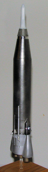
To my knowledge, this is Anigrand's first kit of this kind and they've done a great job on it. The main body of the missile is cast in two very nice halves that in my case were nearly free of any mold defects. Only a small air bubble on an external line was found. The lower halves are the rocket nozzle section. There are three nozzles with the two outer ones being identical. These had a small amount of mold shift to contend with. For the sides of the missile there are varying lengths of fairing. The ones you use will be determined by the variant you decide to build. This will also determine the nose cone that is installed. The X-11/Atlas-A has the rounded tip, X-12/Atlas B has the flatter tip and the XB-65/SM-65/Atlas-D operational missile has the long probe-type tip that is shown on the box art. The kit also includes the large external line between the upper and lower sections and the small steering nozzles.
The kit includes a pair of US insignia to fit along the side. No stand is included so you'll need to supply that. It might also be a good idea to put some weight in the lower section. Some of the resin pour stubs mate right up to the side of some finned areas so you'll need to be careful when cleaning these parts. It really can't be helped.
The instructions are typical Anigrand with an exploded view, history and parts list on one side with painting and markings guide on the other. Each of the different variants is clearly identified and the difference in parts and markings is provided. Another nice thing is no vacuformed canopies!!! Well, that is probably only important to me as I always have trouble with them.
 All resin kits require clean-up of some kind that this one is no exception. I've come to expect to do a bit more with Anigrand kits as they seem to have some air pockets that need filled or a chunk that requires some additional attention. For those who don't build a lot of resin kits, these are generally not a problem, regardless of how scary they look. One simply fills the holes with superglue, applies accelerator on it and sands things smooth. It is imperative that this sanding take place as soon as the accelerator is applied and washed. This is because the superglue is at its 'softest'. If allowed to fully harden, it can be more difficult to remove.
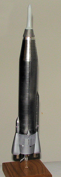
The first step was to choose the version I wanted to do. While all three are good choices, I wanted to do an operational Atlas so chose the tallest one. After sanding any seams and the mating surfaces, I then looked at the pieces for air holes or other areas needing attention. The upper nose cone had some air holes and so did the piece just under it. Those were filled with super glue and later with Mr. Surfacer 500 to take care of any smaller bits. Super glue isn't recommended for tiny holes and the much thinner Mr. Surfacer works a lot better.
The rocket nozzles needed additional care as the mold had slipped on these items, leaving a rather large step in some cases. Were I to complain about anything on resin kits it is that this seems to be a common problem. This can only be 'cured' by more attention to detail and a willingness on the part of the maker to toss any parts that are not fully formed. This rarely happens and the deformation is left to the builder to fix as he can. For things like this, a good set of fine files and scrapers is almost mandatory.
With the parts roughly cleaned up (I do final fixing just before assembly), I glued the main body of the missile. I did this in stages as large resin castings like this are rarely perfectly flat. I started at the top and got that as well aligned as I could. Then, with some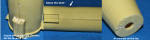 minor shifting and such, did the rest of the body. In the end, I was surprised to find that the parts matched. I also noticed that the body had a 'dent' in the side where the part was probably removed from the mold too fast. This will need attention later, probably with epoxy filler as it is a largish area.
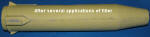 At this time, I did more filling of seams and holes, first using super glue and then Mr. Surfacer. When it was smooth and the detail rescribed, I added on the two extensions to the side pods. There are several options in this area and you need to check the instructions and/or markings guide to see which are appropriate. For the operational Atlas, the shorter and less pointy ones are to be used. These were glued on, matching the upper surface to the surrounding area. I find it easier to fill a small gap than to sand down or fill a step. The usual filler and sanding then took place to fill gaps.
 I then turned my attention to the lower section. These need some special attention as the sprue stubs managed to be attached to a finned area near the top. To fix this, one sands the area flush with the surrounding section. Then a hobby knife is used to make a groove in the filled section. Finally, a thin file with a pointy side is used to gently file out a proper groove. This takes a bit of care to be sure one doesn't go too far, but after a few minutes you won't be able to tell where the attachment point was. These parts also need to have the inside cleaned up as there are small sprue points there as well. If you don't get them all, the lower
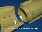
 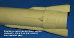 section will not fit. During all this, I test fit these pieces frequently to be sure I wouldn't have any problems. There are alignment pins in the pieces to help and one does have to make sure that the holes for the LOX expansion vent are on the proper side.
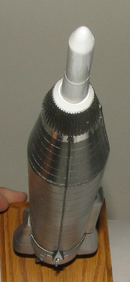
Meanwhile, back at the main body, I filed the top as flush as I could get it and glued on the lower nose section. This needs to line up with a cable duct so one just can't plunk it down anywhere. As I'd rounded that duct off a bit, I needed to build it back up some.
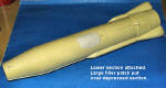
I then attached the lower section pieces to the main body. These were not glued as the pins will keep them in place. The mounting surface was angled out by several degrees so I glued the bottom pieces in sections. I first did one side and clamped those pieces while it dried.
Meanwhile, I glued the two pieces of the nose cone together. These had a bit of a gap between them so I ran additional super glue in that area to fill it. When that had dried, I gave it a coat of primer. This was sanded down some to smooth it out. Then the lower section was painted with Alclad II Steel. It was masked and the upper portion painted with Floquil Reefer White. It showed up an air hole I missed so that was filled with super glue and sanded down.
Back at the main body, I filled and sanded quite a bit on this to take care of the seam along the lower section. A large bit of epoxy filler was placed over the depressed area, and the next day, it was carefully sanded to get it as smooth as I could. The underside was particularly difficult to do because some of the bits are just not easy to get to. When I thought I was done, I gave it a coat of Alclad II primer to find any bits I missed. Man, I missed quite a few more than I thought, so more filler/superglue was used to handle those areas.
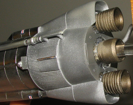 Time to consider some paint. I first sprayed the bits I missed with more primer. Then the main body of the rocket was painted with Alclad II's Gloss Black Base. It is important that this be thoroughly mixed prior to using. I put on a number of thin coats. When dry, I applied a number of thin coats of Airfame Aluminum. This produces quite a shine assuming you don't put it on too thick. It is also darker than I'd have thought, but that is probably due to the black base. The lower section was painted with normal Aluminum and I used jet exhaust (light) misted over with regular exhaust for the nozzles. I also used Aluminum for the expansion vent along the side. The lower vent was painted with Testors Steel.
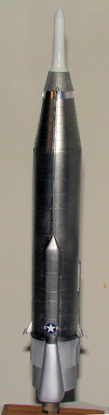
I then glued on the nose cone and made a bit of a mess by using too much glue. It oozed out and marred a section of the upper stage. Not knowing just how to fix this without a lot of masking and sanding, I decided to cover it over with a section of Chrome Bare Metal Foil. I liked the look and used smaller pieces for some bits farther on down in the nozzle section. I also used this in the 'crinkly' area around each nozzle base. The two insignia decals fit well, but even with several applications of Solvaset did not want to snuggle into the engraved panel lines.
 Final bits included gluing on the nozzles. I had to arrange them best as I could to keep the sanded area as difficult to see as I could, but since it is on both sides, that makes it difficult. I also attached the small stabilization nozzles after cleaning them up and painting them aluminum/steel.
Then it was time for a base. I had to have it up off the 'surface' as the final exhaust bit is lower than the bottom of the nozzles. As I did with the Vostok I, I got a short piece of clear plastic rod and drilled two holes in it. Into these holes I put a piece of bronze wire. In the base (thanks to Evanston's extra awards), I drilled a hole and then glued on the short stub. Another hole was drilled into the exhaust port of the middle nozzle. Then, I slathered superglue on the upper portion of the mounting rod and placed the model on it, with the piece of wire running into the lower body to help stabilize it. I had to put books around the rocket to hold it in place while the cement dried. I then glued on the lower exhaust pipe.
 It isn't as sturdy as I'd like it and is best handled by picking it up by the rocket itself. Were I to do it again or do another similar rocket, I'd use a much more sturdy piece of tubing as a support.
On thing about these, you don't weather them as they are not reusable! The subject matter is what sells this kit to me. It makes into a most impressive model that is over a foot and a half tall. I can only hope that this sells well enough for Anigrand to do some others.
References! We don't need no steenking references!November 2006
#1441 in a series.
CopyrightModelingMadness.com. All rights reserved.
If you would like your product reviewed fairly and fairly quickly, please contact the editor or see other details in the Note toContributors.
Back to the Main Page
Back to the Review Index Page
2018


