Testors/Hawk 1/72 Howard DGA-6
| KIT #: | 911 |
| PRICE: | $20.00 |
| DECALS: | One Option |
| REVIEWER: | John Summerford |
| NOTES: | Some scavenged and scratchbuilt part. |
| HISTORY |
Edited from Wikipedia
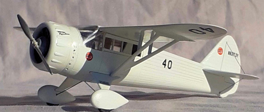
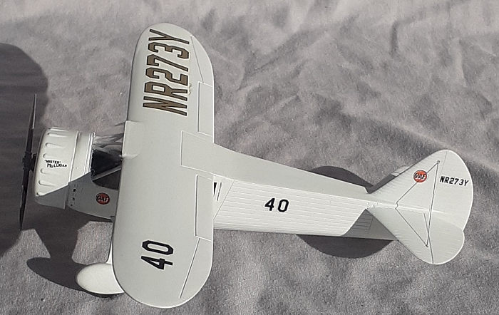
The Howard DGA-6 (Darn Good Airplane) was a pioneer racing plane, nicknamed "Mister Mulligan". It was the only airplane ever designed for the specific purpose of winning the Bendix Trophy. The plane was designed and developed by Ben Howard and Gordon Israel, who later became an engineer for the Grumman Aircraft Engineering Corporation. Mister Mulligan was designed to fly the entire length of the race nonstop and at high altitude. Neither had ever been done before. Mister Mulligan won the trophy, and thus changed the way in which long distance airplanes were designed.
 The single DGA-6 was constructed in 1934 in the
defunct factory of the American Eagle-Lincoln Aircraft based at Fairfax Airport
in Kansas City, Missouri. It featured a steel tube fuselage with a
plywood-skinned wing. Howard freely admitted he was inspired by "seeing the
Monocoupe from the wrong end" during air races.
The single DGA-6 was constructed in 1934 in the
defunct factory of the American Eagle-Lincoln Aircraft based at Fairfax Airport
in Kansas City, Missouri. It featured a steel tube fuselage with a
plywood-skinned wing. Howard freely admitted he was inspired by "seeing the
Monocoupe from the wrong end" during air races.
While enroute to the 1934 air races, oxygen and fuel system problems caused an off-field landing, which damaged the landing gear and propeller. The aircraft could not be repaired in time and missed the 1934 season.
For the 1935 Bendix race the aircraft was loaded with 300 gallons of gasoline, 30 gallons of oil and oxygen equipment for two, giving it the ability to fly for seven hours at 22,000 feet (6,700 m).
Howard and Israel flew the DGA-6 in the 30 August 1935 Bendix Trophy race and won with a speed of 238.70 miles per hour, and Harold Neumann racing the DGA-6 flew at 220.19 mph (354.36 km/h) in winning the 2 September 1935 Thompson Trophy. Howard's engineering advantage was his low-drag airframe and the use of the 850-horsepower (630 kW) Pratt & Whitney Wasp radial. The fuel capacity of the four-seat Mister Mulligan made the difference in the Bendix race, as Howard and Israel beat Roscoe Turner’s 1,000 hp (750 kW) Pratt & Whitney R-1690 Hornet on his Wedell-Williams Model 44 racer.
No other pilot or single aircraft had ever won both races. Howard's DGA-6 also had the distinction of being the only racer during the golden age of airshows to evolve into a successful commercial production aircraft, first as the Howard DGA-8 and DGA-9, and later the DGA-11 and DGA-12.
| THE KIT |
 According to Scalemates, this kit began life in 1949
under the Hawk label. The last boxing was in 1993 and I suspect, being that I
bought the kit still in the wrapping and the parts were taped inside a rolled
bag, this release is more recent. Regardless, the molding is looking long in the
tooth with some dense flash on numerous parts and mold ejection points. This
example had sink marks at the fuselage top. Fortunately, most of the 19
(including a two-part stand and pilot figure) light gray parts were still
attached to the sprues with the one-piece wing separate. Unfortunately, the one
clear part was left loose in the bag but was not scratched. Of note is that the
radial engine, without pushrod tubes, is molded into the cowl. Nor is there any
interior detail. As was customary in the era of the kit’s release, raised
outlines for the race and registration numbers are molded on the surfaces. The
decal sheet of the numbers is sandwiched into the folded size 11 X 17
instructions.
According to Scalemates, this kit began life in 1949
under the Hawk label. The last boxing was in 1993 and I suspect, being that I
bought the kit still in the wrapping and the parts were taped inside a rolled
bag, this release is more recent. Regardless, the molding is looking long in the
tooth with some dense flash on numerous parts and mold ejection points. This
example had sink marks at the fuselage top. Fortunately, most of the 19
(including a two-part stand and pilot figure) light gray parts were still
attached to the sprues with the one-piece wing separate. Unfortunately, the one
clear part was left loose in the bag but was not scratched. Of note is that the
radial engine, without pushrod tubes, is molded into the cowl. Nor is there any
interior detail. As was customary in the era of the kit’s release, raised
outlines for the race and registration numbers are molded on the surfaces. The
decal sheet of the numbers is sandwiched into the folded size 11 X 17
instructions.
| CONSTRUCTION |
A 21st century modeler is presented with a conundrum with this kit. Should it be built in the spirit of the limited post-WWII technology, or try to produce a more contempory model? If the latter choice is selected, how much effort should go into it?
 In my case, I initially wanted a quick simple build,
but as I did more and more on-line research, I found more and more inaccuracies
that I found annoying. Sigh. How deep should I go down this rabbit hole?
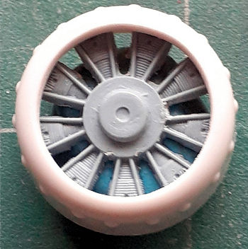
Browsing through my parts stash, I settled on a new engine, add some cockpit
detail, and, aside from a floor, leave the cabin alone.
In my case, I initially wanted a quick simple build,
but as I did more and more on-line research, I found more and more inaccuracies
that I found annoying. Sigh. How deep should I go down this rabbit hole?
Browsing through my parts stash, I settled on a new engine, add some cockpit
detail, and, aside from a floor, leave the cabin alone.
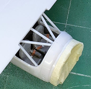
A test fit of the fuselage halves and wing gave me some idea of how to install the frame members that can be seen through the windshield. Those parts were also were cleared of flash and the raised lettering outlines removed.
The fuselage halves were taped together to determine where a disk of .020 styrene could fit as a firewall and mount for the instrument panel. Using a pair of calipers, the diameter was measured at 7/8 inch. Some material had to be removed on the inside, particularly around to locating pin and socket. Once the disk fit well, the cowl/engine piece was test fitted. That fit was reasonable, but the 1/16-inch-thick trailing edge became noticeable. The engine facade was removed by a rotary tool, which was also employed thinning the cowl, followed by some light sanding. The spare engine from the parts bin dropped into place within the cowl. That meant that disk in the cockpit was only needed to support the instrument panel.
Inside each fuselage half is a molded mounting bracket for the bench that the pilot figure sits upon. These were also ground off. The socket for the landing gear fairing were used as a tab to glue the new cabin floor in place. It took constant test fitting and two iterations to get the correct shape for the floor. Finally, there was something to glue together. Once again, the fuselage halves were taped together, this time with the disk in place. The floor was inserted through the windshield opening and glued to the right half.
 Also in the parts bin was a sprue fragment of seats.
Two were removed and strips of HO scale 4 X 8 (.043 X .090) styrene were glued
to the bottom to elevate them. Neutral gray paint was brushed on and a black
wash applied in the cervices. When they were dry, seatbelts fabricated from card
stock were added, then glued to the floor.
Also in the parts bin was a sprue fragment of seats.
Two were removed and strips of HO scale 4 X 8 (.043 X .090) styrene were glued
to the bottom to elevate them. Neutral gray paint was brushed on and a black
wash applied in the cervices. When they were dry, seatbelts fabricated from card
stock were added, then glued to the floor.
Instead of fabricating an instrument panel, one was painted on the disc with two-tone gray and dials marked with a felt tip pen. Brass rod of 1mm was wrapped around a small screwdriver shank into a horseshoe shape to serve as control yokes. A rod was glued across the back side of each, followed by a disc punched out of .020 styrene to simulate a hub on the front. Once painted black, they were glued into place.
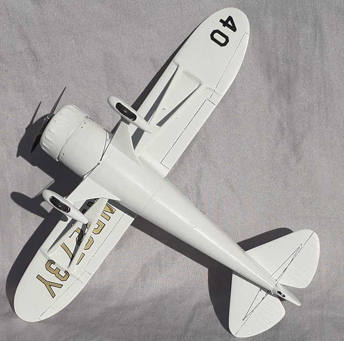
A two-tone interior was applied by brush. The instrument panel was added and the fuselage halves glued together. Seams and sink marks were filled and sanded. Unfortunately, no longerons are molded on the topside. I didn’t bother with that detail and went with the flat surface. The kit has a spreader bar between the wheels. Photos show that this is incorrect. Instead, V-shaped bracing was employed. Holes in the fuselage were drilled for that rigging as well as in the fin and stabilizers.
 Next, the wing was glued on, followed by addressing
the seam at the top of the fuselage.
Next, the wing was glued on, followed by addressing
the seam at the top of the fuselage.
Before installing the frame members behind the windshield, a test fit of the clear part revealed a poor fit. After careful filing and sanding, it eventually settled into place, but with gaps at the top and bottom of the windshield and it rested proud of the fuselage aft the wing. The frame members were cut to length from 3/64-inch styrene rod, which might be overscale, and then painted light gray.
Rather than install the clear part after painting, it was installed next and putty was used to fill the gaps. Unfortunately, blobs filler could be viewed at the top, so they were hidden by not masking them and be covered by paint.
Moving to the landing gear, the sockets for the spreader bar in the spats were filled and holes for the wire drilled. The spats were glued together and then to the struts and each assembly attached to the fuselage.
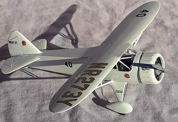
Even though the notches in the wing strut fairings are too deep, they make it easy to glue them in place. Filling and sanding around this area proved to be a challenge and I was unable to get a good result. I did notice in photos that secondary bracing struts were attached to the main struts. Using a pair of dividers and the underwing registration number decal, their placement was identified. The dividers were next used to determine the length of airfoil stock to cut. With those in place, it was time for paint.
| COLORS & MARKINGS |
A rattle can of automotive light gray primer was used for the first coat. That revealed more filling and sanding was required. Another quick primer coat and then a coat of Tru-Color Insignia White slightly thinned and retarded. After that set up, a gloss coat, also with retarder followed.
Decaling was straight forward, although, because of the carrier film around the printing, it was a little difficult to align the fuselage decals with the raised boarders. A bit of Micro-Sol got them to settle down nicely.
 Using a twisting motion with a narrow tipped felt pen,
the exhaust stubs were darkened. A dark wash was brushed into the hinge lines on
the underside control surfaces. The wash was inconsistent, so on the top side,
the backside of a knife tip cleaned the lines. I liked the result so much that I
dispensed with the wash.
Using a twisting motion with a narrow tipped felt pen,
the exhaust stubs were darkened. A dark wash was brushed into the hinge lines on
the underside control surfaces. The wash was inconsistent, so on the top side,
the backside of a knife tip cleaned the lines. I liked the result so much that I
dispensed with the wash.
The glazing was unmasked and, unfortunately, some bleed occurred at the lower edge of the windshield. Attempts to scrape it off were unsuccessful, so it was left alone (*%$#!)
The tail was rigged with thread and painted steel. Two segments of .015-inch music wire served as the landing gear rigging, then the wheels inserted into the spats. The engine was glued into the cowl, making sure that cylinders align with the bumps, then glued onto the fuselage.
As per my custom, the prop was the final piece.
| CONCLUSIONS |
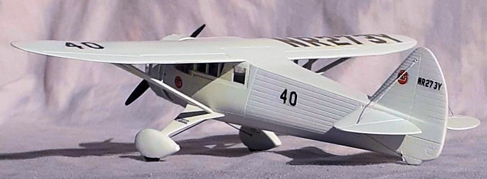
So, was this a quick and relaxing build? Not as quick as I initially thought. Was it a fun build? Absolutely!
Parts fit is generally good after cleaning up and their low number kept things simple, which did, however, sacrifice accuracy. The DGA-6 is a handsome aircraft and this kit produces a likewise model, although I suspect the fuselage height should be greater to create a steeper slope in the windshield. It is also a good ride to use going down a “more accurate” rabbit hole. At the very least, an aftermarket engine plus seats should be used in any build of this kit.
If I were to go all the way to the bottom of the hole, I would also;
Scribe an outline of the cabin door on the right fuselage half.
Fill the trenches for panel lines and re-scribe them.
Use the smallest diameter half-round rod stock to simulate stringers at the top of the fuselage. The sink mark there would be filled with a slurry of sprue runner segments dissolved in liquid cement first. After using liquid cement to attach the rods, I would brush coat more cement over them to blend into the fuselage.
Sand the rest of the stringers to match the top.
Remove all of the decal locators.
Remove the rear most frame segment for the glazing so that it would fit flush.
Install shims to fill the gaps at the front of the windshield.
Also use shims to make the wing struts fit better in their fairings.
Build up a fairing on the bottom of the fuselage for the landing gear bracing wire.
Also create fairings around the wires at the spats.
Create navigation light lenses.
Run a file and scriber along the hinge lines of the elevator and rudder
Could a 21st century manufacturer produce a more accurate kit? Certainly.
| REFERENCES |
Thompson Trophy Racers by Roger Huntington
The Air Racer by Charles Mendenhall (Drawings of aircraft from the late 20s to the late 70s)
8 January 2024
Copyright ModelingMadness.com. All rights reserved. No reproduction in part or in whole without express permission.
If you would like your product reviewed fairly and fairly quickly, please contact the editor or see other details in the Note to Contributors.