| KIT #: | 48019 |
| PRICE: | $39.99 |
| DECALS: | Three options |
| REVIEWER: | Rob Hart |
| NOTES: | Short run |
| HISTORY |
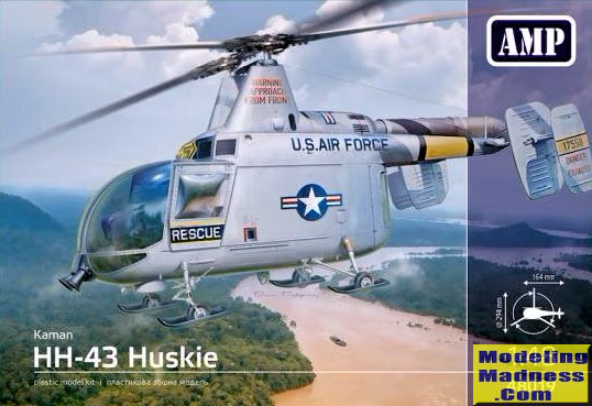
The Kaman HH-43B was largely designed by the German aeronautical engineer Anton Flettner. Flettner had been brought to the United States in 1947 as part of Operation Paperclip. In Germany during WWII he had developed a couple of helicopters using counter-rotating side-by-side intermeshing rotors as a means to solve the problem of torque compensation, normally countered in single-rotor helicopters by a tail rotor. Flettner remained in the United States and became the chief designer of the Kaman company.
The helicopter that would eventually be developed into the HH-43B made its first flight in April, 1953. This machine would lead to a series of piston engined rotorcraft designated HTK-1, HUK-1, and H-43A for the USMC, USN, and USAF respectively. The USAF also opted to procure two models that were powered by a Lycoming T-53 turboshaft engine, the HH-43B with 860 horsepower and the HH-43F with 825 horsepower. The HH-43B variant would set numerous records for rate of climb, altitude, and distance flown.
Flight control on the HH-43 was primarily effected by a series of servo-flaps, or large tabs, that was located on the trailing edge of each rotor blade; the actuation of these flaps would cause the rotors to warp and thus cause the helicopter to either rise or descend as desired. There was no conventional tail rotor, its absence gave the rotorcraft a somewhat unusual look. The contra-rotating twin rotors posed a particular hazard on the ground; crews were instructed to avoid approaching or departing the vehicle from the sides, but to instead advance or leave the vehicle from the front, as the blades would be at their highest at this position. Warnings that reinforced this instruction were usually painted on the sides of the pylons which supported the rotor heads.
The U.S. Air Force primarily procured the HH-43B to perform local base rescue operations and to fight aircraft fires. The HH-43B entered service in 1959 and was deployed overseas during the . Vietnam War. During the conflict, the HH-43 flew more rescue missions than all other rotorcraft combined, largely due to its unique hovering capability; between 1966 and 1970, the type performed a total of 888 combat rescue, comprising 343 aircrew rescues and 545 non-aircrew rescues. The type was also occasionally used as a firefighting vehicle in the theatre as well. A1C William H Pitsenbarger was posthumously awarded the Medal of Honor for actions taken while serving as a HH-43F pararescueman during the Vietnam War. The march of technology caused the HH-43 to be replaced by newer helicopters in the early 1970s .
| THE KIT |
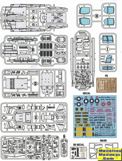 The AMP 1/48 Kaman HH-43B Huskie is a limited run kit. The kit parts are
packaged in resealable plastic bags inside of a sturdy top opening box. The kit
has 148 plastic parts, 25 photo-etched parts, a set of vinyl masks, and a small
sheet of 3D decals for the instrument panel, console tops, and seat belts. The
16 page instruction booklet illustrates 56 assembly steps along with painting
and decal placement guides.
The AMP 1/48 Kaman HH-43B Huskie is a limited run kit. The kit parts are
packaged in resealable plastic bags inside of a sturdy top opening box. The kit
has 148 plastic parts, 25 photo-etched parts, a set of vinyl masks, and a small
sheet of 3D decals for the instrument panel, console tops, and seat belts. The
16 page instruction booklet illustrates 56 assembly steps along with painting
and decal placement guides.
The first 19 assembly steps are for construction of the comprehensively detailed cockpit and cabin interiors. The kit offers 1/48 scale reproductions of all instrumentation, flight controls, electronic boxes, crew accommodations, and bulkheads. The fuselage sidewalls have molded on representations of the formers and longerons. Completing the construction of the cabin and cockpit interiors will require the builder to install 102 individual plastic and photo-etched parts into an area that is 3 inches long by 1 3/8 inches tall by 1 1/8 inches wide. Some of the parts are simply short plastic rods. I think that replacing them with plastic or metal rods cut to size may be easier than cleaning up the sprue attachment points and the mold parting lines of the kit parts.
With the cockpit and cabin complete, the side edges of the cabin floor are attached to the to the left and right side fuselage walls and the belly pan is glued to the lower edges of the fuselage side walls. The cabin ceiling is attached to raised lips on the insides of the fuselage walls which is followed followed by joining the fuselage roof and an aerodynamic fairing to the upper edges of the fuselage walls.
The next several steps are for gluing the halves of the main and nose wheels together, assembling the bracket that that spans the tops of the rotor pylons, joining the halves of the exhaust pipe, and constructing the loudspeakers that will go on the nose of the helicopter.
The rotor pylons and engine nacelle are assembled next They are then joined to an aerodynamic fairing that will form a portion of the fuselage roof.
The nose and mail landing gear are constructed from a wheel/tire, a leg, a skid, and multiple supporting struts. Some of the nose wheel struts are photo-etched. There are two nose landing gear and two main landing gear assemblies.
At this point the instructions call for joining the halves of the windshield (the seam runs down the middle of the frame that divides the windshield) and attaching a panel with a couple of windows to the rear upper edge of the completed windshield. A small console with a 3D decal is attached to the inside of the top center windshield frame. The instructions indicate that the loudspeaker assembly should now be attached to the windshield, but I recommending waiting until further into the assembly process to do this.
Assembly of the rotor blades are next followed by joining the top and bottom halves of the horizontal stabilizer. The four fin/rudders are then attached to the stabilizer. Several small photo-etched parts are attached to the fins and stabilizer along with a pair of long thin styrene rods that represent bracing and connect the innermost fins.
Next the side doors have their tiny photo-etched handles attached. The doors are molded in clear styrene and will need to have the windows masked and the doors painted. The masks provided cover both the inside and outside of the windows. The winch/hoist is then assembled and the fin/stabilizer assembly is joined to the ends of the tail booms. The tail booms have slots that the stabilizer slides into. Two long and thin photo-etched pieces that span the space between the tail booms are positioned to form an “X” and attached at the front and rear of the tail booms. Their purpose also appears to be bracing.
The rotor pylon/engine nacelle sub-assembly is attached to the fuselage roof and the exhaust pipe is joined to the engine nacelle. The windshield sub-assembly, the side doors, and the rear clamshell doors are then attached to the fuselage. The side and rear doors can be posed open. Photos of SEA based machines show that the rear doors were frequently removed and replaced by restraining nets that varied in size and pattern. . The kit does not provide an example of the nets, but it shouldn't be too hard to fabricate one from strips of paper or tape.
Next the winch, landing gear, and various sensors/probes/antennae are attached to the fuselage. Construction of the model is completed by attaching the rotor blades to the rotor pylons.
Three decal options are provided. Two are for USAF machines and the third is for a Royal Thai Air force bird. All three of the machines are in painted silver finishes. The two USAF examples have black bordered yellow bands around their tail booms while the Thai machine has red fins and cockpit doors. One of the USAF machines also has two red bands around each rotor blade. The Thai example and one of the USAF subjects are museum exhibits, The other USAF machine is from MATS Rescue at Berlin-Tempelhof, Germany in 1965.
| CONCLUSIONS |
This is not a kit for novices. I wouldn't recommend it to experienced builders for a first helicopter model either. The kit's high parts count, small size, and unusual configuration add up to what is certain to be a challenging building experience. No placement guides are provided for the kit's masks and although some locations are easily deduced by matching the shapes of the masks to the shapes of the clear parts, others are not easily determined. I have no doubt that this kit can be turned into a gem of a model, but it will take a lot of time, patience, and enthusiasm.
January 2024
Copyright ModelingMadness.com. All rights reserved. No reproduction in part or in whole without express permission from the editor.
If you would like your product reviewed fairly and fairly quickly, please contact the editor or see other details in the Note to Contributors.