| KIT #: | CP 48019 |
| PRICE: | $39.00 |
| DECALS: | One option |
| REVIEWER: | Tom Berto |
| NOTES: | Kit includes the ground cart |
| HISTORY |
The D-21 rose from a 1962 CIA/USAF requirement for a means to photograph military sites deep in Chinese or Soviet territory without putting a pilot at risk. The A-12 was already flying by then and could serve as a launch platform, so the D-21 could be air-launched at extremely high speed, allowing the use of a ramjet engine. The simplicity of ramjets doesn’t just make them lower cost; with almost no constraint on exhaust temperature (Look Mom! No turbine!) they can use fuel-air ratios that produce exhaust beyond white-hot, allowing great efficiency. The D-21 also leveraged the experience gained from the A-12 in stealth design and the use of titanium.
The drone would fly to the reconnaissance point, take pictures, turn around, drop the camera pack (a bulge in the underside of the forward fuselage), then self-destruct. The camera pack would drift down under its parachute to be snagged by a C-130, in the same manner as film cannisters were retrieved from Corona spy satellites.
 The first
free flight test was on March 5, 1966. In order to more cleanly separate the
drone from the M-21 (the M-21 was the version of the A-12 adapted for use as a
drone launcher), the M-21 had to fly an outside loop during release, a slight
push-over. Two other tests were performed with this technique, but on July 30,
1966, a fourth launch was attempted with the M-21 flying straight and level. The
drone did not separate cleanly, and knocked off one of the vertical stabilizers
of the M-21. Both M-21 crew members were able to eject, but upon parachuting
into the ocean, one drowned.
The first
free flight test was on March 5, 1966. In order to more cleanly separate the
drone from the M-21 (the M-21 was the version of the A-12 adapted for use as a
drone launcher), the M-21 had to fly an outside loop during release, a slight
push-over. Two other tests were performed with this technique, but on July 30,
1966, a fourth launch was attempted with the M-21 flying straight and level. The
drone did not separate cleanly, and knocked off one of the vertical stabilizers
of the M-21. Both M-21 crew members were able to eject, but upon parachuting
into the ocean, one drowned.
Kelly Johnson, legendary Lockheed designer, suggested that the D-21 be air-launched from a B-52H Stratofortress, from pylons located between the inboard engine pairs and the fuselage. The B-52 already had hard-points on its wings for attachment of Hound Dog cruise missiles, on their pylons. To attain the necessary velocity for the ramjet to function, a solid rocket booster was used, attached underneath the D-21 and generating 27,300 pounds of thrust. After an 87-second burn, the combination was going fast enough for the ramjet to function. The D-21 was modified into the D-21B, which had increased fin area, and a means to hang onto the booster while it was accelerated to Mach 3 in 87 seconds.
Everything finally went perfectly on the sixth test. Even then, the system was still not completely reliable, but gradually improving test results led to the operational use of the D-21 from November 1969 to March 1971. D-21s made four attempts to photograph the Chinese nuclear test site near the Lop Nur dry lake. All four failed: on the first, the drone didn’t turn and ended up in the Soviet Union; next, the camera pack parachute didn’t fully deploy. On the third, the C-130 recovery failed, and the destroyer sent to pick up the camera pack off the surface of the ocean rammed it and sank it. On the final flight, the drone failed over China. A large piece of it is displayed in the China Aviation Museum in Beijing. The program was cancelled in 1971, as spy satellites could do the work with a lot less fuss.
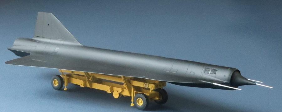
Thirty-eight D-21s were made. Twenty-one were consumed in testing or missions, leaving 17 at the end of the program. Once the program details emerged in 2003, the 17 were dispersed to various museums around the country. The Pacific Coast Air Museum (PCAM) in Santa Rosa, CA has one, on a ground-handling cart that is missing more than a few pieces.
 The D-21’s
form is absurdly simple. It showed what Kelly Johnson and his team could do when
presented with a design challenge with a minimum of trade-offs. Form follows
function, and its form was simple because the required function was simple: the
D-21 is 200-proof “go fast.” With its speed and minimal radar cross section –
particularly from the front – it would have been very difficult to intercept.
The D-21’s
form is absurdly simple. It showed what Kelly Johnson and his team could do when
presented with a design challenge with a minimum of trade-offs. Form follows
function, and its form was simple because the required function was simple: the
D-21 is 200-proof “go fast.” With its speed and minimal radar cross section –
particularly from the front – it would have been very difficult to intercept.
I built this model for John Hazlett, Major USAFR Retired. John joined the US Air Force in September 1963, and the D-21 program in January 1968, attaining the requisite Top Secret clearance. He was a B-52 navigator, and so was involved with the D-21 program only after it transitioned to using the B-52 as the mother ship. John was part of the 4200th Support Squadron at Beale AFB, and for his first year in the program, while the facilities at Beale were being prepared for the D-21, he flew weekly to Dreamland (Area 51): “Out on Monday and back home on Friday.” By 1969, the facility at Beale was complete, and all the work was done there.
He was on board for one launch, and also for several flights to evaluate the drone with it remaining attached to the pylon. John left active service with the air force in July 1970 and retired from the reserves and National Guard in 1985. It is my pleasure to know him, and building this model for him was an honor and a delight.
| THE KIT |
Clear Prop’s D-21 comes in a small,
stout box, with beautiful cover art. The parts are molded in medium gray
styrene, with exquisite surface detail. There is one clear piece, two
judiciously chosen pieces of photo-etch, and a decal sheet that you’ll miss if
you blink. The drone, if built with the inlet and exhaust exposed (as if on an
actual mission) is built from 18 gray plastic parts, the clear plastic part, and
the two photo-etched pieces. An additional nine parts are used to model the
front and rear nosepieces, which were u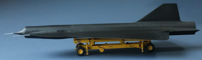 sed
when testing while remaining attached to the M-21. John wisely requested that
the drone be displayed mounted on its ground-handling cart, and so I built that,
too. The cart has 71 parts!
sed
when testing while remaining attached to the M-21. John wisely requested that
the drone be displayed mounted on its ground-handling cart, and so I built that,
too. The cart has 71 parts!
The kit includes the blade-like pylon for attaching the D-21 to an M-21, with finding a 1/48th scale M-21 left as a problem for the builder.
The kit is called a D-21A on the box and in the instructions, but this is incorrect. The first version was just the D-21. The second version was the D-21B. Parts F26 and F30 are the two chine fronts with pitot tubes. They are marked as “do not use,” as they were exclusive to the D-21B, but as that was the version John was involved with, I was delighted to have them on hand. Those two parts hint strongly that there will be a D-21B air-launched version of this kit in the near future – but what I could do for John in The Now was the simple conversion of a kit of a D-21 into a model of the D-21B.
| CONSTRUCTION |
I pre-painted the ramjet interior and flame holder satin black. In Step 2, I think it would have been better to join A1 and A2 (the two top fuselage halves) before attaching the ramjet. I installed the ramjet on one side first, and I had a small gap in the seam behind the vertical stabilizer. I filled that with stretched sprue, melted into place with copious amounts of Weld-On 3.
Step 4: before joining the top and bottom fuselages, capturing the inlet cone holder E11, don’t forget to install part X1, the clear window for the camera bay! In fact, make this Step 0 – do it right away. I forgot. If you plan to follow the instructions and install X1 first, skip the following paragraph:
As it’s roughly square, I was able to thread X1 through the square opening from below (this is why manhole covers are round). Before doing that, I drilled a hole directly above the opening, right through the fuselage top seam. After coaxing X1 into place and getting it to settle into the opening (gravity helped here), I glued it in place with Weld-On, while pushing it against the internal ledge with a rod coming through hole in the fuselage seam. My pusher left a visible mark on the window’s inside, so I flooded the joint with Weld-On, and pushed harder on the window, to get a strong joint. I later puttied and sanded it flush, coming back after painting with a rectangular patch of Future, two coats, to make it look like a window again. I filled the tooling hole on the fuselage top with a cone of sprue, taken from that part of the stretched sprue where it necks into a conical taper, then sanded and polished that flush.
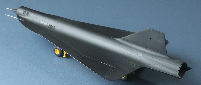
The wings are molded as one piece each. The model handles all of the graceful wing-body blend in the fuselage: the wing pieces are simple, nearly flat parts, with just a hint of shrink marks in the flat square tabs that provide fore/aft alignment. At the join to the fuselage, the top surfaces of the wings extend past the bottom surfaces, to mate up against the fuselage assembly, from which the bottom fuselage half extends past the top fuselage half. The result is a lap joint, instead of just a butt joint. The lap joint configuration is exceedingly strong.
 Good thing.
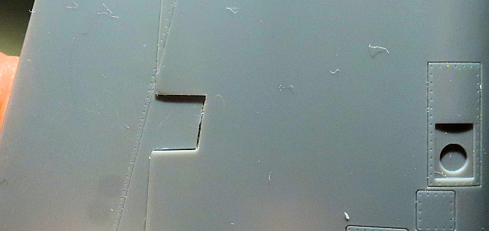
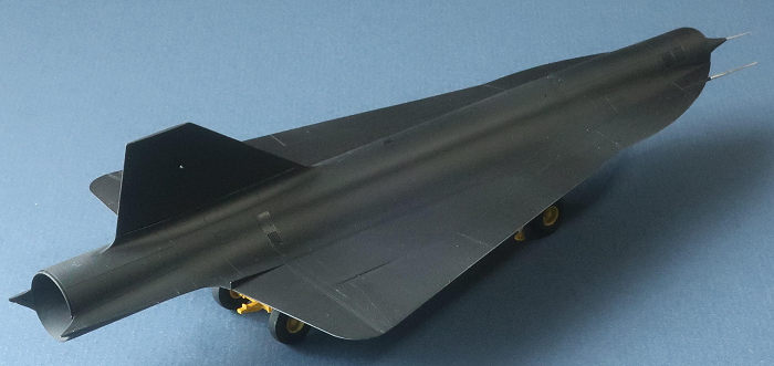
Unfortunately, on each side, the protruding part of part B1, the lower fuselage,
is thicker than the height of the mating step in the wing part. So when one
mates the wings up to the fuselage assembly, there is a step in thickness on the
underside of the wing. The thickness mismatch is worst at the front – it’s about
0.010”. The photo shows this step, in glancing light, at one of the two
alignment tabs. The photo also shows how nice the surface detail is.
Good thing.
Unfortunately, on each side, the protruding part of part B1, the lower fuselage,
is thicker than the height of the mating step in the wing part. So when one
mates the wings up to the fuselage assembly, there is a step in thickness on the
underside of the wing. The thickness mismatch is worst at the front – it’s about
0.010”. The photo shows this step, in glancing light, at one of the two
alignment tabs. The photo also shows how nice the surface detail is.
This is the only flaw in this kit that is more than minor. By the time I discovered it, the top and bottom fuselage halves were united, married, death-do-us-part. The way to have solved it would have been to flat-sand B1 to reduce its thickness – before attaching the top fuselage assembly. I belatedly half-solved it on each side by scraping away plastic from that protruding part of the lower fuselage, to reduce its thickness until it was a better match for the step in the underside of the wing. I had to stop short, because this caused a step to develop in the top of the wing, which is more visible. I opted to leave the step in the bottom. And I think I stopped a little too soon. I did not follow Cleaver’s Rule: “Test fit three times before gluing once.” In my defense, the fate of my wing-fuselage joint had been sealed one step earlier – I would have had to have test fit one entire step ahead.
There were also gaps in the tops of the wing-fuselage joints – the top of the wing didn’t reach the top of the fuselages. I filled the gaps with thick-ish stretched sprue, once again melted into place with copious amounts of Weld-On, for maximum strength and to use a “like material” as filler. It would have been a better idea to trim the lower fuselage to reduce the gap. Cleaver’s Rule ignored, again.
I scraped, filed, puttied, sanded, puttied, sanded, puttied, sanded... until the step disappeared. This obliterated a lot of the surface detail, unfortunately. I didn’t do a perfect job of it, but “perfect is the mortal enemy of the good”, and the lap joints held.
After that battle, I attached the
vertical stabilizer. The tab in the fuselage was a bit thicker than the slot in
the stab assembly, so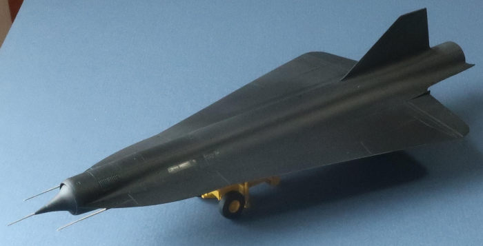 I thinned the tab down so the stabilizer would fit over it. The vertical
stabilizer has a hole through it. I don’t know what its function was, but it
must have whistled like a banshee at Mach 3. I could not determine how the
D-21B’s vertical stabilizer differed from that of the D-21, so I just used the
kit part.
I thinned the tab down so the stabilizer would fit over it. The vertical
stabilizer has a hole through it. I don’t know what its function was, but it
must have whistled like a banshee at Mach 3. I could not determine how the
D-21B’s vertical stabilizer differed from that of the D-21, so I just used the
kit part.
Completion of construction involved attaching the remaining parts in order from least to most delicate.
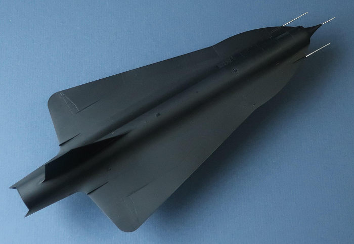
I had already assembled the inlet cone from its two halves. By the way, unlike the purely conical inlet cones of the SR-71, the D-21 appears to have a “four-shock” inlet cone, close to theoretically perfect. The isentropic ideal is a smooth variation in curvature, like an elongated titanium-flavored chocolate kiss. Since the drone’s ramjet was going to be operating only at Mach 3.3 at 90,000 feet, the inlet cone’s form could be made as close as possible to the theoretical optimum for that one condition, forming three oblique shocks and one normal shock, yielding nearly the maximum pressure rise as the incoming air decelerated to subsonic on its way into the ramjet. The curvy cone also makes the D-21 look even more like an alien love child.
Anyway, I attached this theoretically nearly ideal cone, then the two photo-etch vanes at the inside ends of the elevons, then parts F26 and F30, the chines with pitot tubes. The pitot tube for the tip of the inlet cone was attached after painting. Note that the inlet cone, all three pitot tubes, and the lip of the inlet all tilt downward. This tilt counteracted the angle of attack of the drone, so the pitot tubes and inlet all pointed straight into the incoming air as the drone was screaming along at its primary operating point, Mach 3.3 at 90,000 feet.
Next, I assembled the cart. The cart had tires, casters, and jacks. My guess is that the tires were for towing the drone over long distances, the casters were for when it was close to the correct position, and the jacks were when it was almost perfectly positioned under the pylon, and needed only vertical and pitch adjustments. The real cart is welded up from sections of C-beams, I-beams, box beams, and gussets, with two arc-shaped bars and rollers that allowed the cart’s top half (with drone attached) to rotate relative to the bottom half, rolling the drone relative to the pylon.
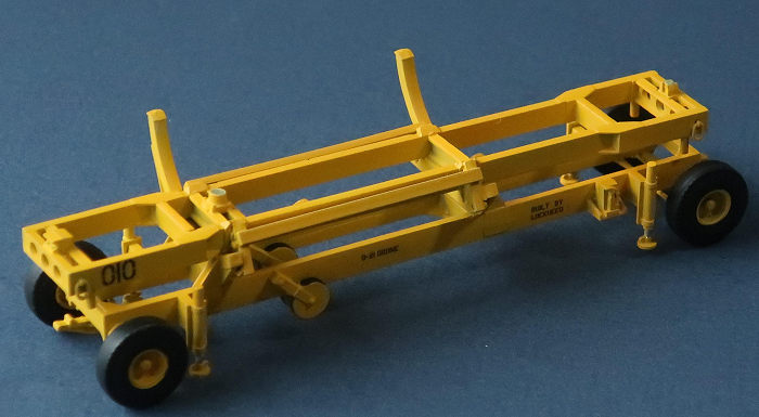 Clear Prop
went all-in on the cart, molding almost every piece of beam of it individually.
Flash removal is needed for parts to mate well, and it’s like building a
rectilinear bird’s nest, but the final look is outstanding. My only suggestions
are these:
Clear Prop
went all-in on the cart, molding almost every piece of beam of it individually.
Flash removal is needed for parts to mate well, and it’s like building a
rectilinear bird’s nest, but the final look is outstanding. My only suggestions
are these:
In Step 9, attach F16 and F17 to the frame first, then the two parts E4 to the tips of F16 and F17. That way, F16 and F17 can attach to the frame wherever they’d like, and parts E4 will just bridge the distance between them. I followed the opposite sequence, and parts E4, which are slender, buckled at first, as F16 and F17 naturally attached to the frame too close together.
Step 14: the cart top will, without a hint of protest, attach backward to the cart bottom. Done correctly, the top and bottom frames line up. Done wrong, the top and bottom are offset about an inch.
Attach of part F28 is better left until after Step 16, and the notch indicated as its attachment point in the Step 15 illustration is incorrect. The small inset view between Steps 15 and 16 shows where it should go.
The road wheels and the four casters are best painted before attach.
| COLORS & MARKINGS |
The D-21B was painted the same
color as the Ford Model T, but photos show variations in tone between panels. I
skewered the drone on a vertical dowel mounted in a vise, and sprayed it overall
with satin black, a thinned 50/50 mix of Testors flat and gloss black (the
little square bottles). After letting that dry and harden for a day, I masked
individual panels and selectively buffed them to give them a sheen, varying the
dire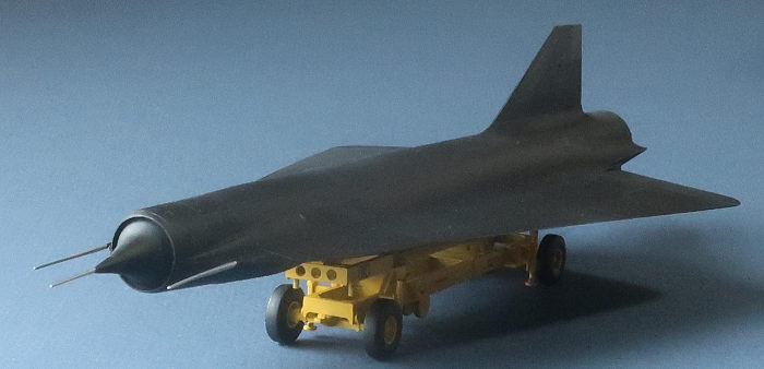 ction and
intensity of the buffing between panels. That gave the variation between panels
that I wanted - but everything was still black.
ction and
intensity of the buffing between panels. That gave the variation between panels
that I wanted - but everything was still black.
There should be a drone number in white characters, on each side of the nose and also on the vertical stabilizer. These are D-21B markings and so didn’t come with this kit. Options for adding them would be to use dry transfers, as decals would not be compatible with the buffed black satin. Fortunately, John was content with just the overall black, which matches the unmarked sample at PCAM.
The cart color schemes are all blue, blue/yellow, and all yellow. John chose the all-yellow scheme. I sprayed a base coat of flat white, then flat yellow. I locally glossed up the decal areas with Future, then added the cart number and the other relevant decals.
| FINAL CONSTRUCTION |
I attached the front pitot tube. While handling the model later that day, that pitot tube disappeared, flicked off into a parallel universe which resembles a shag carpet, full of small model parts donated by modelers since the Big Bang. Every modeler has a cosmic wormhole in their build area, through which small parts quantum tunnel. To replace the pitot, I used yet another piece of stretched sprue, once again choosing a piece at the start of the stretched portion, where it had a conical taper at the base.
 The
kit-provided alignment between cart and drone is not adequate – there is
alignment at the front, but not the back, so the drone could easily be installed
rotated off-axis from the cart. The instructions show the drone attaching at
just those two points on the cart, so I channeled Roger Jackson and installed
two fat pieces of styrene rod at those two points on the cart, and drilled two
corresponding holes on the bottom centerline of the drone. I set the drone on
the cart, and noted that the right wing was high. It was being forced up by the
tops of the arc-shaped cart rails, so I sanded the rail tops until the drone sat
wingtips level. The pins and holes made the joint repeatable. I then got the
four points (two each, on cart and drone) sticky with Weld-On, and set the drone
on the cart. It quickly engaged on the pins, with no tilt, and the glue set up.
Hurrah!
The
kit-provided alignment between cart and drone is not adequate – there is
alignment at the front, but not the back, so the drone could easily be installed
rotated off-axis from the cart. The instructions show the drone attaching at
just those two points on the cart, so I channeled Roger Jackson and installed
two fat pieces of styrene rod at those two points on the cart, and drilled two
corresponding holes on the bottom centerline of the drone. I set the drone on
the cart, and noted that the right wing was high. It was being forced up by the
tops of the arc-shaped cart rails, so I sanded the rail tops until the drone sat
wingtips level. The pins and holes made the joint repeatable. I then got the
four points (two each, on cart and drone) sticky with Weld-On, and set the drone
on the cart. It quickly engaged on the pins, with no tilt, and the glue set up.
Hurrah!
I did not glue the tips of the arc-shaped cart rails to the wing underside. The drone at PCAM rests on its cart at three (not two) central points – but the tips of the arc rails are not touching.
| CONCLUSIONS |
Highly recommended. This is a great kit. From Ukraine, of an aircraft that has its own little corner in the universe of aircraft designs. It is well within the range of a modeler of moderate skills and patience, and will yield a model that will stand out in any model collection. The only gotcha is at the wing/fuselage joint, and the only definite change I would recommend is to add the two alignment pins and holes, to make the cart/drone joint repeatable.
| REFERENCES |
Personal recollections of John Hazlett
“Aircraft Design: A Conceptual Approach” by Daniel P Raymer, AIAA Education Series
Wikipedia
Tom Berto
19 February 2024
Copyright ModelingMadness.com. All rights reserved. No reproduction in part
or in whole without express permission from the editor. If you would like your product reviewed fairly and fairly quickly, please
contact
the editor or see other details in the
Note to
Contributors. Back to the Main Page
Back to the Review
Index Page
Back to the Previews Index Page